MEN NL31 User manual

User Manual
NL31
Robust 12-Port Fully Managed Ethernet Switch with PoE
Layer 2/3 Switch with M12 Front Connectors & Fiber Option
2019-02-1320NL31-00 E1

20NL31-00 E1 2019-02-13 Page 2
Contents
Contents
Contents. . . . . . . . . . . . . . . . . . . . . . . . . . . . . . . . . . . . . . . . . . . . . . . . . . . . . . . . . . 2
About this Document . . . . . . . . . . . . . . . . . . . . . . . . . . . . . . . . . . . . . . . . . . . . . . 4
Product Safety . . . . . . . . . . . . . . . . . . . . . . . . . . . . . . . . . . . . . . . . . . . . . . . . . . . . 6
Product Compliance . . . . . . . . . . . . . . . . . . . . . . . . . . . . . . . . . . . . . . . . . . . . . . . 7
Disclaimer . . . . . . . . . . . . . . . . . . . . . . . . . . . . . . . . . . . . . . . . . . . . . . . . . . . . . . . . 8
Contacts . . . . . . . . . . . . . . . . . . . . . . . . . . . . . . . . . . . . . . . . . . . . . . . . . . . . . . . . . . 9
1 Product Overview . . . . . . . . . . . . . . . . . . . . . . . . . . . . . . . . . . . . . . . . . . . . . . 10
1.1 Product Description . . . . . . . . . . . . . . . . . . . . . . . . . . . . . . . . . . . . . . . . . . . . . . .10
1.2 Product Architecture . . . . . . . . . . . . . . . . . . . . . . . . . . . . . . . . . . . . . . . . . . . . . .11
1.2.1 Interfaces. . . . . . . . . . . . . . . . . . . . . . . . . . . . . . . . . . . . . . . . . . . . . . . .11
1.2.2 Functions. . . . . . . . . . . . . . . . . . . . . . . . . . . . . . . . . . . . . . . . . . . . . . . .12
1.3 Technical Data . . . . . . . . . . . . . . . . . . . . . . . . . . . . . . . . . . . . . . . . . . . . . . . . . . . .13
1.4 Cooling Concept . . . . . . . . . . . . . . . . . . . . . . . . . . . . . . . . . . . . . . . . . . . . . . . . . .16
1.5 Product Identification. . . . . . . . . . . . . . . . . . . . . . . . . . . . . . . . . . . . . . . . . . . . . .16
2 Getting Started . . . . . . . . . . . . . . . . . . . . . . . . . . . . . . . . . . . . . . . . . . . . . . . . 17
2.1 Unpacking the NL31 . . . . . . . . . . . . . . . . . . . . . . . . . . . . . . . . . . . . . . . . . . . . . . .17
2.2 Mounting the NL31. . . . . . . . . . . . . . . . . . . . . . . . . . . . . . . . . . . . . . . . . . . . . . . .17
2.2.1 Safety Instructions for Mounting . . . . . . . . . . . . . . . . . . . . . . . . . . . . 18
2.2.2 Mounting on a Wall or a Horizontal Surface . . . . . . . . . . . . . . . . . .18
2.3 Connecting and Starting . . . . . . . . . . . . . . . . . . . . . . . . . . . . . . . . . . . . . . . . . . .19
2.3.1 Safety Instructions for Connection . . . . . . . . . . . . . . . . . . . . . . . . . .19
2.3.2 Connecting an Earthing Cable . . . . . . . . . . . . . . . . . . . . . . . . . . . . . .20
2.3.3 Connecting the Devices. . . . . . . . . . . . . . . . . . . . . . . . . . . . . . . . . . . .20
2.3.4 Connecting the Power Supply . . . . . . . . . . . . . . . . . . . . . . . . . . . . . .21
2.4 Accessing the Ethernet Switch . . . . . . . . . . . . . . . . . . . . . . . . . . . . . . . . . . . . . .22
2.4.1 Web Interface . . . . . . . . . . . . . . . . . . . . . . . . . . . . . . . . . . . . . . . . . . . .22
2.4.2 Command Line Interface (CLI) . . . . . . . . . . . . . . . . . . . . . . . . . . . . . .22
2.5 Configuring Basic Switch Settings. . . . . . . . . . . . . . . . . . . . . . . . . . . . . . . . . . . .23
2.5.1 Resetting the Configuration to Factory Defaults . . . . . . . . . . . . . . .24
2.5.2 Setting the Device Hostname . . . . . . . . . . . . . . . . . . . . . . . . . . . . . . . 24
2.5.3 Setting a Password for the Admin User . . . . . . . . . . . . . . . . . . . . . .24
2.5.4 Setting the VLAN 1 IP Address . . . . . . . . . . . . . . . . . . . . . . . . . . . . . .25
2.5.5 Displaying and Saving the Configuration . . . . . . . . . . . . . . . . . . . . .26
3 Functional Description. . . . . . . . . . . . . . . . . . . . . . . . . . . . . . . . . . . . . . . . . . 28
3.1 Power Supply. . . . . . . . . . . . . . . . . . . . . . . . . . . . . . . . . . . . . . . . . . . . . . . . . . . . .28
3.2 Isolation Voltages . . . . . . . . . . . . . . . . . . . . . . . . . . . . . . . . . . . . . . . . . . . . . . . . .28
3.3 Ethernet . . . . . . . . . . . . . . . . . . . . . . . . . . . . . . . . . . . . . . . . . . . . . . . . . . . . . . . . .29
3.3.1 PoE+ Power Supply . . . . . . . . . . . . . . . . . . . . . . . . . . . . . . . . . . . . . . .29
3.3.2 Front Connection . . . . . . . . . . . . . . . . . . . . . . . . . . . . . . . . . . . . . . . . .30
3.3.3 Power over Ethernet (PoE) . . . . . . . . . . . . . . . . . . . . . . . . . . . . . . . . .34
3.3.4 Ethernet Status LEDs . . . . . . . . . . . . . . . . . . . . . . . . . . . . . . . . . . . . . .34
3.3.5 Ethernet Switch . . . . . . . . . . . . . . . . . . . . . . . . . . . . . . . . . . . . . . . . . .34
3.4 RS232 (Console). . . . . . . . . . . . . . . . . . . . . . . . . . . . . . . . . . . . . . . . . . . . . . . . . . . 35
3.4.1 Front Connection . . . . . . . . . . . . . . . . . . . . . . . . . . . . . . . . . . . . . . . . .35

20NL31-00 E1 2019-02-13 Page 3
Contents
3.5 Status LEDs . . . . . . . . . . . . . . . . . . . . . . . . . . . . . . . . . . . . . . . . . . . . . . . . . . . . . .36
4 Switch Firmware . . . . . . . . . . . . . . . . . . . . . . . . . . . . . . . . . . . . . . . . . . . . . . . 37
5 Maintenance . . . . . . . . . . . . . . . . . . . . . . . . . . . . . . . . . . . . . . . . . . . . . . . . . . 38
5.1 Cleaning . . . . . . . . . . . . . . . . . . . . . . . . . . . . . . . . . . . . . . . . . . . . . . . . . . . . . . . . . 38
5.2 Updating the Switch Firmware . . . . . . . . . . . . . . . . . . . . . . . . . . . . . . . . . . . . . .38
Figures
Figure 1. Front interfaces . . . . . . . . . . . . . . . . . . . . . . . . . . . . . . . . . . . . . . . . . . . . . . . . . . .11
Figure 2. Functional diagram . . . . . . . . . . . . . . . . . . . . . . . . . . . . . . . . . . . . . . . . . . . . . . . .12
Figure 3. Product label. . . . . . . . . . . . . . . . . . . . . . . . . . . . . . . . . . . . . . . . . . . . . . . . . . . . . .16
Figure 4. Power configuration and coding labeling . . . . . . . . . . . . . . . . . . . . . . . . . . . . .21
Figure 5. Accessing the help option . . . . . . . . . . . . . . . . . . . . . . . . . . . . . . . . . . . . . . . . . . 22
Tables
Table 1. Connector types – power supply (4-pin M12 A-coded). . . . . . . . . . . . . . . . . . .28
Table 2. Pin assignment - power supply (4-pin M12 A-coded) . . . . . . . . . . . . . . . . . . . .28
Table 3. Signal mnemonics – power supply . . . . . . . . . . . . . . . . . . . . . . . . . . . . . . . . . . .28
Table 4. Isolation voltages (with A- or/and D-coded connectors) . . . . . . . . . . . . . . . . . 28
Table 5. Isolation voltages (with X-coded connectors) . . . . . . . . . . . . . . . . . . . . . . . . . .28
Table 6. Connector types – 5-pin, M12, L-coded. . . . . . . . . . . . . . . . . . . . . . . . . . . . . . . .29
Table 7. Pin assignment - power supply (5-pin M12 L-coded) . . . . . . . . . . . . . . . . . . . .29
Table 8. Signal mnemonics – power supply . . . . . . . . . . . . . . . . . . . . . . . . . . . . . . . . . . .29
Table 9. Connector types – Ethernet (4-pin, M12, D-coded) . . . . . . . . . . . . . . . . . . . . . . 30
Table 10. Pin assignment – Ethernet (4-pin M12). . . . . . . . . . . . . . . . . . . . . . . . . . . . . . . .30
Table 11. Signal mnemonics – Ethernet. . . . . . . . . . . . . . . . . . . . . . . . . . . . . . . . . . . . . . . .30
Table 12. Connector types – Ethernet (8-pin M12). . . . . . . . . . . . . . . . . . . . . . . . . . . . . . .31
Table 13. Pin assignment – Ethernet (8-pin M12). . . . . . . . . . . . . . . . . . . . . . . . . . . . . . . .31
Table 14. Signal mnemonics – Ethernet. . . . . . . . . . . . . . . . . . . . . . . . . . . . . . . . . . . . . . . .31
Table 15. Connector types – Ethernet M12 . . . . . . . . . . . . . . . . . . . . . . . . . . . . . . . . . . . . . 32
Table 16. Pin assignment – Ethernet (8-pin M12). . . . . . . . . . . . . . . . . . . . . . . . . . . . . . . .32
Table 17. Signal mnemonics – Ethernet. . . . . . . . . . . . . . . . . . . . . . . . . . . . . . . . . . . . . . . .32
Table 18. Connector types – Q-ODC. . . . . . . . . . . . . . . . . . . . . . . . . . . . . . . . . . . . . . . . . . .33
Table 19. Pin assignment – Q-ODC. . . . . . . . . . . . . . . . . . . . . . . . . . . . . . . . . . . . . . . . . . . .33
Table 20. Signal mnemonics – Q-ODC . . . . . . . . . . . . . . . . . . . . . . . . . . . . . . . . . . . . . . . . .33
Table 21. Power over Ethernet classes . . . . . . . . . . . . . . . . . . . . . . . . . . . . . . . . . . . . . . . . 34
Table 22. Ethernet status LEDs . . . . . . . . . . . . . . . . . . . . . . . . . . . . . . . . . . . . . . . . . . . . . . . 34
Table 23. Default switch configuration . . . . . . . . . . . . . . . . . . . . . . . . . . . . . . . . . . . . . . . .34
Table 24. Connector types – RS232 M12 . . . . . . . . . . . . . . . . . . . . . . . . . . . . . . . . . . . . . . .35
Table 25. Pin assignment – RS232 M12 . . . . . . . . . . . . . . . . . . . . . . . . . . . . . . . . . . . . . . . . 35
Table 26. Signal mnemonics – RS232 M12 . . . . . . . . . . . . . . . . . . . . . . . . . . . . . . . . . . . . .35
Table 27. General status LEDs at front panel . . . . . . . . . . . . . . . . . . . . . . . . . . . . . . . . . . .36

20NL31-00 E1 2019-02-13 Page 4
About this Document
About this Document
This document is intended only for system developers and integrators.
It describes the design, functions and connection of the product. The manual does not
include detailed information on individual components (data sheets etc.).
History
NL31 product page with up-to-date information and downloads:
www.men.de/products/nl31/
Issue Comments Date
E1 First issue 2019-02-13

20NL31-00 E1 2019-02-13 Page 5
About this Document
Conventions
Indicates important information or warnings concerning situations which
could result in personal injury, or damage or destruction of the
component.
Indicates important information concerning electrostatic discharge which
could result in damage or destruction of the component.
Indicates important information or warnings concerning proper
functionality of the product described in this document.
The globe icon indicates a hyperlink that links directly to the Internet.
When no globe icon is present, the hyperlink links to specific information
within this document.
Italics Folder, file and function names are printed in italics.
Comment Comments embedded into coding examples are shown in green text.
IRQ#
/IRQ
Signal names followed by a hashtag "#" or preceded by a forward slash "/"
indicate that this signal is either active low or that it becomes active at a
falling edge.
In/Out Signal directions in signal mnemonics tables generally refer to the
corresponding board or component, "in" meaning "to the board or
component", "out" meaning "from the board or component".
0xFF Hexadecimal numbers are preceded by "0x".
0b1111 Binary numbers are preceded by "0b".

20NL31-00 E1 2019-02-13 Page 6
Product Safety
Product Safety
Read the user manual carefully before using the product. Keep the user manual for later
reference.
Conditions for Use, Field of Application
The product is designed to function correctly in the market, application area and
environmental conditions specified in the applicable standards which are listed in the
Technical Data.
Use cases in environments exceeding the specifications in the applicable standards and
the Technical Data have to be agreed upon between MEN and the customer.
Electrostatic Discharge (ESD)
Qualified Personnel
The product/system described in this documentation may be operated only by
personnel qualified for the specific task in accordance with the relevant documentation,
in particular its warning notices and safety instructions. Qualified personnel are those
who, based on their training and experience, are capable of identifying risks and
avoiding potential hazards when working with these products/systems.
Computer boards and components contain electrostatic sensitive devices.
Electrostatic discharge (ESD) can damage components. To protect the PCB
and other components against damage from static electricity, follow some
precautions whenever you work on your computer.
Power down and unplug your computer system when working on the
inside.
Hold components by the edges and try not to touch the IC chips, leads,
or circuitry.
Use a grounded wrist strap before handling computer components.
Place components on a grounded antistatic pad or on the bag that came
with the component whenever the components are separated from the
system.
Only store the product in its original ESD-protected packaging. Retain
the original packaging in case you need to return the product to MEN for
repair.
20NL31-00 E1 2019-02-13 Page 7
Product Compliance
Product Compliance
MEN products are no ready-made products for end users. They are tested according to
the standards given in the Technical Data and thus enable you to achieve certification of
the product according to the standards applicable in your field of application.
If the product delivered was certified by MEN and is modified by the customer, e.g., by
installing an additional hardware component, the certification achieved by MEN
becomes invalid and has to be repeated for the new product configuration.
RoHS
MEN is committed to develop and produce environmentally compatible products
according to the Restriction of Hazardous Substances (RoHS) Directive 2011/65/EU
(formerly 2002/95/EC) of the European Union.
Since July 1, 2006 all MEN standard products comply with RoHS legislation.
REACH
MEN is a manufacturer of electronic products and thus a so-called "downstream user" in
terms of REACH. The products MEN supplies are solely non-chemical goods. Moreover
and under normal and reasonably foreseeable circumstances of application, the goods
supplied shall not release any substance.
Beyond that, according to REACH – Art.33, MEN will inform the customer immediately
should a substance contained in an MEN product (with a content of > 0.1%) be classified
alarming by the European Chemicals Agency (ECHA).
WEEE Application
Nevertheless, MEN is registered as a manufacturer in Germany. The registration number
can be provided on request.
The WEEE directive does not apply to fixed industrial plants and tools. The
compliance is the responsibility of the company which puts the product
on the market, as defined in the directive; components and sub-
assemblies are not subject to product compliance.
Since MEN does not deliver ready-made products to end users, the WEEE
directive is not applicable for MEN. Users are nevertheless recommended
to properly recycle all electronic boards which have passed their life cycle.

20NL31-00 E1 2019-02-13 Page 8
Disclaimer
Disclaimer
Changes
MEN Mikro Elektronik GmbH ("MEN") reserves the right to make changes without further
notice to any products herein.
Liability
MEN makes no warranty, representation or guarantee of any kind regarding the
suitability of its products for any particular purpose, nor does MEN assume any liability
arising out of the application or use of any product or circuit, and specifically disclaims
any and all liability, including, without limitation, consequential or incidental damages.
TO THE EXTENT APPLICABLE, SPECIFICALLY EXCLUDED ARE ANY IMPLIED WARRANTIES
ARISING BY OPERATION OF LAW, CUSTOM OR USAGE, INCLUDING WITHOUT LIMITATION,
THE IMPLIED WARRANTIES OF MERCHANTABILITY AND FITNESS FOR A PARTICULAR
PURPOSE OR USE. In no event shall MEN be liable for more than the contract price for
the products in question. If buyer does not notify MEN in writing within the foregoing
warranty period, MEN shall have no liability or obligation to buyer hereunder.
Should the customer purchase or use MEN products for any unintended or
unauthorized application, the customer shall indemnify and hold MEN and its officers,
employees, subsidiaries, affiliates, and distributors harmless against all claims, costs,
damages, and expenses, and reasonable attorney fees arising out of, directly or
indirectly, any claim or personal injury or death associated with such unintended or
unauthorized use, even if such claim alleges that MEN was negligent regarding the
design or manufacture of the part. In no case is MEN liable for the correct function of the
technical installation where MEN products are a part of.
The publication is provided on the terms and understanding that:
1. MEN is not responsible for the results of any actions taken on the basis of
information in the publication, nor for any error in or omission from the publication; and
2. MEN is not engaged in rendering technical or other advice or services.
MEN expressly disclaims all and any liability and responsibility to any person, whether a
reader of the publication or not, in respect of anything, and of the consequences of
anything, done or omitted to be done by any such person in reliance, whether wholly or
partially, on the whole or any part of the contents of the publication.

20NL31-00 E1 2019-02-13 Page 9
Contacts
Contacts
Copyright © 2019 MEN Mikro Elektronik GmbH. All rights reserved.
Germany
MEN Mikro Elektronik GmbH
Neuwieder Straße 1-7
90411 Nuremberg
Phone +49-911-99 33 5-0
France
MEN Mikro Elektronik SAS
18, rue René Cassin
ZA de la Châtelaine
74240 Gaillard
Phone +33-450-955-312
www.men.de
www.men-france.fr
USA
MEN Micro Inc.
860 Penllyn Blue Bell Pike
Blue Bell, PA 19422
Phone 215-542-9575
China
MEN Mikro Elektronik (Shanghai) Co., Ltd.
Room 1215, #993 West Nanjing Road
Shanghai 200041
Phone +86-21-5058-0963
www.menmicro.com
www.men-china.cn

Product Overview
20NL31-00 E1 2019-02-13 Page 10
1 Product Overview
1.1 Product Description
"NL" Family Principle
MEN's "NL" Ethernet switch family principle is based on a wide range of configuration
options (e.g., amount of Ethernet ports, fiber connections or Power over Ethernet) to
easily adapt the switch to application requirements.
Flexible Concept in a Small Housing
The NL31 is a 12+2-port fully managed layer 2/3 Ethernet switch, providing a wide range
of configuration options with 12 M12 Gigabit Ethernet ports. M12 connectors can be
configured to be A-, D- or X-coded and combinations are also possible. The X-coded
connectors are designed as push-pull and screwed variants (Harting concept). The NL31
offers two optional Ethernet fiber ports with 1000BASE-SX as standard variant. The
mechanical concept is an extremely compact, high-quality aluminum housing providing
high port density and ultra-high ruggedness. It is designed for wall-mounting, but
mounting in a 19" rack is also an option.
Performance, Security and Diagnostic Features
The 29 Gbit/s, TCAM based, store-and-forward switching matrix of the NL31 allows high-
performance layer 2 switching over all connected interfaces. For easy remote
management and access, layer 3 protocols, e.g., IPv4/IPv6 and DHCP, are integrated. The
switch provides extended security features like SNMPv3, SSH and HTTPS. Traffic isolation
(VLAN) and switching redundancy protocols (e.g., STP, RSTP, MSTP) provide safe running
of the network using redundant data paths in the event of a fault. The ITU-T G.8031/
G.8032 ring and linear protection switching feature set makes NL31 able to create
network ring scenarios with recovery time under 50 ms. Monitoring and diagnosis
functions, e.g., sFlow or SNMPv1, v2c, v3 are provided.
Wide-Range Power Supply and Power over Ethernet
The EN 50155 compliant supply voltage range of 24 V DC to 110 V DC provides maximum
flexibility for using the switch. The NL31 comes with internal Power over Ethernet for 10
ports with a maximum of 30 W per port and a total of 90 W. With external PoE supply
PU28, up to 300 W PoE output power are available (in load sharing mode with internal
PoE power supply).
Maintenance Free and Extremely Rugged
The NL31 is designed for fanless operation at temperatures ranging from -40 °C to
+70 °C (10 min @ +85 °C). The cooling fins serve as a heat sink for the internal
electronics. It is maintenance-free and developed specifically for rough environmental
conditions in rolling stock applications. Long-term availability until 2026 from product
start minimizes lifecycle management by making the system available at least for this
period of time.

Product Overview
20NL31-00 E1 2019-02-13 Page 11
1.2 Product Architecture
1.2.1 Interfaces
Figure 1. Front interfaces
Power
Power over
Ethernet
Gigabit Ethernet
with Status LEDs
Status LED
(Power)
Switch
Operaon
LED
PoE Power
Status LED
Console Port
(RS232)
Fiber Uplink
(oponal)
ETH26
Fiber Uplink
(oponal)
ETH25
Product Overview
20NL31-00 E1 2019-02-13 Page 12
1.2.2 Functions
Figure 2. Functional diagram
FPowerin PSU
UART
FPoEPowerin
F1000BASE‐SX
F1000BASE‐SX
F27LEDs
F
PoEPSU
FFront Options
10xGigabitEthernet
F
F
F
GigabitEthernet
GigabitEthernet
Bypass
Relay
PoE+
Vitesse
EthernetSwitch
PoE+
Product Overview
20NL31-00 E1 2019-02-13 Page 13
1.3 Technical Data
Switch Key Features
Switching Matrix
-Total switching capacity of chipset: 29 Gbit/s
-MAC address table size: 8192
-Switching algorithm: Store-and-forward, TCAM high-speed (Ternary Content-
Addressable Memory)
General Network Support
-IPv4
-IPv6
-IPv6 Ready Logo approved
Protocols and Functionality
-DHCP ARP inspection
-DHCP Option 82
-DHCP Server/Client
-DHCP snooping
-DNS Client (RFC 2136)
-DNS Proxy (RFC 5625)
Ports and Port Control
-Energy Efficient Ethernet (IEEE 802.3az)
-ETH Signal Equalization and Power Control
-Inband management (VRAP)
-Port frame size (Jumbo Frames: 9216 bytes/packet max.)
-Port state (admin), speed, duplex mode and flow control
-Port status (link monitoring) and statistics (MIB counters)
-Port VeriPHY (cable diagnostics), ActiPHY and PerfectReach
User Configuration Interfaces
-Command line interface (CLI) via console, SSHv2, Telnet
-Web interface (HTTP/HTTPS) via IPv4, IPv6
Power Over Ethernet
PSE (Power Sourcing Equipment)
Supply classes 0, 1, 2, 3, 4
Number of PoE ports: 10
Total PoE power available: 90 W (300 W with external power supply)
See the firmware product page for more information on the switch
firmware features:
www.men.de/software/14etsw-02/
Product Overview
20NL31-00 E1 2019-02-13 Page 14
Interfaces
Ethernet
-2x 1000BASE-SX, Q-ODC, receptacle
-12x 10/100/1000BASE-T, M12, X-coded, receptacle
-12x 10/100/1000BASE-T, M12, A-coded, receptacle
-10x 10/100BASE-T, M12, D-coded, receptacle
-2x 10/100/1000BASE-T, M12, A-coded, receptacle
-D-coded connectors are typically combined with two A-coded connectors for
uplink.
Serial
-1x RS232, M12, A-coded, receptacle
LED
-Status: power status, system status
-Ethernet: link, activity
Power
-1x power in, M12, A-coded, plug
-1x PoE in, M12, L-coded, plug
Supervision and Control
Temperature measurement
Watchdog timer
Electrical Specifications
Supply voltage
-24 V DC to 110 V DC nom. (EN 50155)
-52 V DC (PoE+)
Power consumption
-130 W max. (with maximum PoE load)
Mechanical Specifications
Dimensions
-(W) 390 mm, (D) 236 mm, (H) 89 mm
Weight: 6 kg max.
Mounting possibilities
-Wall-mount
-Rack-mount in 19" cabinet
Cooling
-Air cooling, natural convection, airflow 0.4 m/s
Protection rating: IP30
Please contact MEN sales for component combination possibilities.

Product Overview
20NL31-00 E1 2019-02-13 Page 15
Product Compliance: Rail - Rolling Stock
Operating temperature: -40 °C to +70 °C, +85 °C for 10 min (EN 50155:2017, class
OT4, ST1)
Storage temperature: -40 °C (EN 50155:2017) to +85 °C (EN 60068-2-2, Bb)
Humidity: +55 °C and +25 °C, 100 % max. (EN 50155:2017)
Shock: 30 ms @ 50 m/s² (EN 61373:2010/AC:2017-09, vehicle body, cat. 1, class B)
Vibration: 10 min @ 2.02 m/s² and 5 h @ 11.44 m/s² (EN 61373:2010/AC:2017-09,
vehicle body, cat. 1, class B x 2)
Power supply
-General compliance with power supply requirements of EN 50155:2017
-Interruption of voltage supply: 10 ms (EN 50155:2017, class S2)
Electrical Safety
-EN 50155:2017
-EN 50153:2014 + A1:2017
-EN 50124-1:2017
-EN ISO 13732-1:2008
Fire protection: EN 45545-2:2013 + A1:2015, HL3
EMC emission
-EN 50121-3-2:2016
-Regelung Nr. EMV 06 :2014-07-29, Anhang E: Messung an Geräten
EMC immunity: EN 50121-3-2:2016
Useful life: 20 years (EN 50155:2017, class L4)
Protective coatings: EN 50155:2017, class PC2 (Any PCB protected on both sides)
Reliability
MTBF: 350 000 h @ 40 °C according to IEC/TR 62380 (RDF 2000)
Product Overview
20NL31-00 E1 2019-02-13 Page 16
1.4 Cooling Concept
The NL31 is cooled by natural convection for fanless operation.
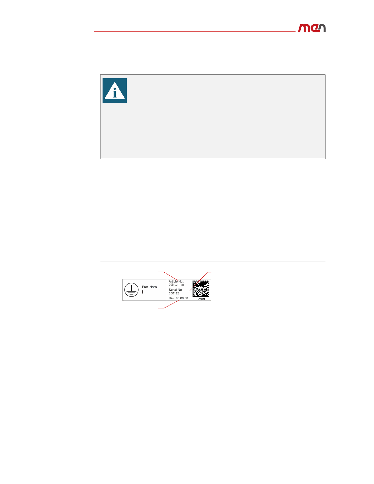
1.5 Product Identification
MEN documentation may describe several different models and design revisions of the
NL31. You can find the article number, design revision and serial number affixed to the
NL31.
Article number: Indicates the product family and model. This is also MEN’s main
ordering number. To be complete it must have 9 characters.
Revision number: Indicates the design revision of the product.
Serial number: Unique identification assigned during production.
If you need support, you should communicate these numbers to MEN.
Figure 3. Product label
Leave the following minimum space to all sides of the system that are
needed for cooling to enable the required airflow:
15 cm
The following sides are needed for cooling:
top
front
rear
left
right
x
Revisionnumber
Serialnumber
Completearticlenumber
Getting Started
20NL31-00 E1 2019-02-13 Page 17
2 Getting Started
2.1 Unpacking the NL31
After unpacking, check whether there are any transport or other damages on the
system. If one of the following situations arises, have the equipment checked by service
personnel:
The power cable or plug is damaged.
Liquid has penetrated into the equipment.
The equipment has been exposed to moisture.
The equipment has been dropped and damaged.
The equipment has obvious signs of breakage.
2.2 Mounting the NL31
Before installing the NL31, make sure that the installation site has been prepared and
that the operating environment meets the equipment requirements.
The NL31 network box has been designed to either sit on a flat surface or be securely
mounted to a wall or similar surface.
Electric Shock and Fire Hazard Caused by Damaged Device
Damaged equipment may be under dangerous voltage and can cause fire.
Damaged equipment has unpredictable behavior and characteristics.
Prevent damaged equipment from being installed and put into
operation.
Mark the damaged equipment and keep it under lock and key.
Send the equipment to repair immediately.
Damage from Condensation
When the equipment has been subjected to low temperatures or extreme
temperature variations, condensation can form on or inside the system.
Humidity causes short circuits in electric circuits and damages the system.
To avoid damages, do the following:
Store the equipment in a dry environment.
Ensure that the equipment has the same temperature as the
environment before starting it up.
Do not subject the equipment to the direct radiation of a heating device.
Wait until the equipment has dried completely or wait 12 hours before
switching on the equipment.
Please check all hardware requirements before mounting the NL31, as
any modifications necessary to the system are difficult, or even
impossible to do after the network box has been mounted.
Please make sure to use the connectors listed in this manual. Other
connectors might cause damage to the device.
Getting Started
20NL31-00 E1 2019-02-13 Page 18
2.2.1 Safety Instructions for Mounting
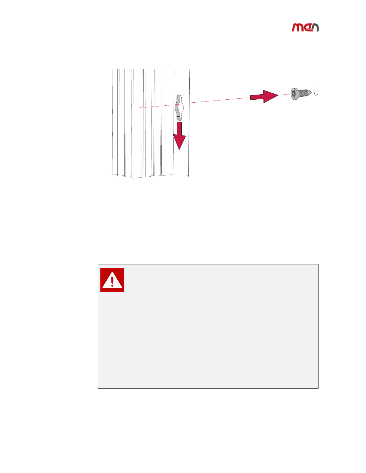
2.2.2 Mounting on a Wall or a Horizontal Surface
The following steps are necessary:
»Carefully measure and mark the position of the required screw holes to match the
position of the mounting holes on the NL31.
»Drill the screw holes for the M5 pan-head screws at the marked location.
»Secure the M5 pan-head screws at the marked location, making sure to leave at
least the following gap between the surface and the screw head:
-5 mm
»Place the NL31 so that the wide openings of the mounting holes are over the screw
heads (1).
Risk of Damages or Injuries
Make sure that the cabinet or the wall where you want to install the
system supports the weight of the system.
Risk of Fire Through Overheating
Make sure that the equipment does not overheat. Overheating can cause
fire or malfunction of the device. Conformity to standards expires.
Mount the equipment only in the mounting position described in this
document.
Adhere to the environmental conditions specified in the Technical Data.
Leave enough space to the sides of the system that are needed for
cooling to enable the required airflow as specified in chapter Cooling
Concept.
Do not install the system near any heat sources (e.g., radiators, heaters).
Risk of Damage Through Liquids
Keep the system away from liquids. Avoid exposure to dripping or
splashing.
The necessary length of the M5 screws to mount the NL31 depends
on the structure of the surface.
Getting Started
20NL31-00 E1 2019-02-13 Page 19
»Slide the box down so that the screw heads slip into the narrow part of the mount-
ing hole (2).
»Securely tighten the mounting screws to prevent potential damage which could be
caused by, e.g., vibration. The recommended tightening torque is between 2.0 Nm
and 2.2 Nm.
2.3 Connecting and Starting
2.3.1 Safety Instructions for Connection
Adhere to the following safety instructions before you connect the NL31:
Works on the computer system may only be carried out by personnel
qualified for the specific task, who, based on their training and
experience, are able to identify risks and avoid potential hazards when
working with these products/systems.
Any power input must be protected by an external fuse as defined in
chapter Connecting the Power Supply.
Implement a readily accessible disconnect device external to the
system.
Read all labels and warnings on the equipment carefully; especially the
power configuration and coding label affixed to the system chassis.
Make sure that the voltage supplied by the external power supply
conforms with the voltage given on the power configuration and coding
label.
Adhere to the wiring rules valid in your country when connecting the
system.
2
1
Getting Started
20NL31-00 E1 2019-02-13 Page 20
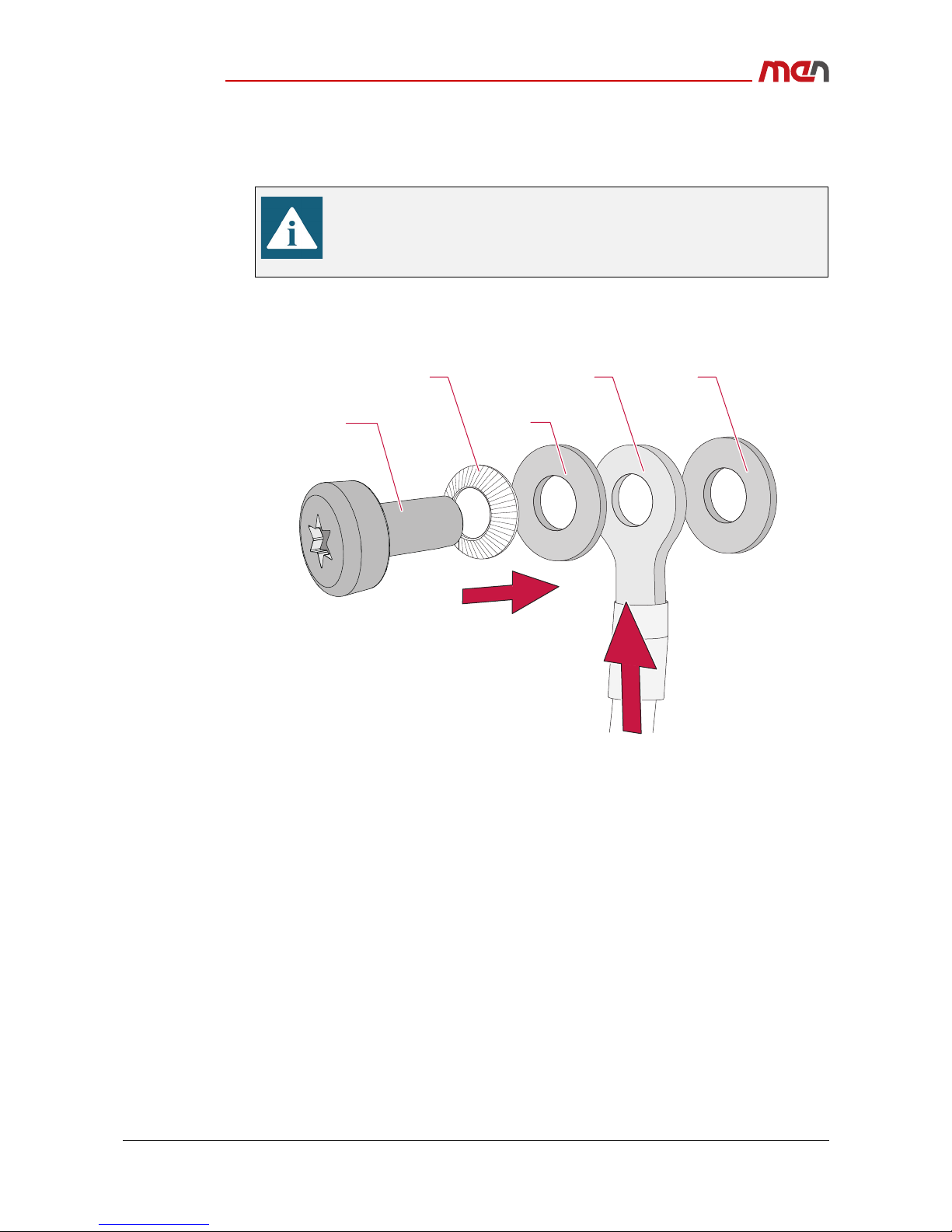
2.3.2 Connecting an Earthing Cable
The NL31 features an earthing connection.
Carry out the following steps to connect the earthing cable:
»Use an earthing cable with a cross section of at least 4 mm².
»Align the spring washer, the washer and the earthing cable over the M6 screw.
»Carefully place the screw with all aligned parts over the screw hole and fasten the
screw with a tightening torque of 3.5 Nm.
- For supply voltages 24 V DC and 36 V DC nominal:
This connection is a functional ground.
- For supply voltages 48 V DC to 110 V DC nominal:
This connection is a low impedance ground path for electrical safety.
2.3.3 Connecting the Devices
»Connect all Ethernet devices to be served.
Connect the earthing cable before making any other connections!
A protective earth connection is essential for the system to meet its EMC
specifications.
When disassembling the system, always detach the earthing cable last.
Spring washer Earthing cable Screw hole
WasherScrew
Table of contents
Other MEN Network Router manuals


Popular Network Router manuals by other brands

AVM
AVM Fritz!Box 3490 Configuration and operation manual

PRO-NETS
PRO-NETS WR850RL user manual

Alcatel-Lucent
Alcatel-Lucent OmniAccess 5840 installation manual

BEC
BEC 7402GTM Reference manual

D-Link
D-Link Amplifi DIR-657 Quick installation guide

Accton Technology
Accton Technology MR3201A Quick installation guide


