Phoenix Contact FL MGUARD RS4000 User manual

User manual
Installing and starting up the
mGuard hardware

2018-02-21
PHOENIX CONTACT 105656_en_05
Installing and starting up the mGuard hardware
UM EN MGUARD DEVICES
05
—
This user manual is valid for the following devices of the mGuard product range:
– FL MGUARD RS4000
– FL MGUARD RS2000
– FL MGUARD RS4004
– FL MGUARD RS2005
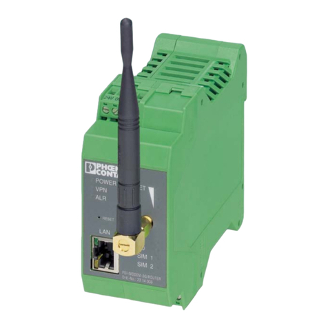
– TC MGUARD RS4000 3G
– TC MGUARD RS2000 3G
– TC MGUARD RS4000 4G
– TC MGUARD RS2000 4G
– FL MGUARD RS2000 TX/TX-B
– FL MGUARD RS4000 TX/TX-P
– FL MGUARD RS4000 TX/TX VPN-M
– FL MGUARD GT/GT
–FLMGUARDSMART2
– FL MGUARD PCI(E)4000
–FLMGUARDCENTERPORT
– FL MGUARD DELTA TX/TX
User manual
Designation:
Revision:
Order No.:

PHOENIX CONTACT
Please observe the following notes
User group of this manual
The use of products described in this manual is oriented exclusively to qualified electricians
or persons instructed by them, who are familiar with applicable standards and other regula-
tions regarding electrical engineering and, in particular, the relevant safety concepts.
Explanation of symbols used and signal words
How to contact us
Internet Up-to-date information on Phoenix Contact products and our Terms and Conditions can be
found on the Internet at:
phoenixcontact.com
Make sure you always use the latest documentation.
It can be downloaded at:
phoenixcontact.net/products
Subsidiaries If there are any problems that cannot be solved using the documentation, please contact
your Phoenix Contact subsidiary.
Subsidiary contact information is available at phoenixcontact.com.
Published by PHOENIX CONTACT GmbH & Co. KG
Flachsmarktstraße 8
32825 Blomberg
GERMANY
Should you have any suggestions or recommendations for improvement of the contents and
layout of our manuals, please send your comments to:
tecdoc@phoenixcontact.com
This is the safety alert symbol. It is used to alert you to potential personal injury
hazards. Obey all safety measures that follow this symbol to avoid possible in-
jury or death.
There are three different categories of personal injury that are indicated with a
signal word.
DANGER This indicates a hazardous situation which, if not avoided, will re-
sult in death or serious injury.
WARNING This indicates a hazardous situation which, if not avoided, could
result in death or serious injury.
CAUTION This indicates a hazardous situation which, if not avoided, could
result in minor or moderate injury.
This symbol together with the signal word NOTE and the accompanying text
alert the reader to a situation which may cause damage or malfunction to the
device, hardware/software, or surrounding property.
This symbol and the accompanying text provide the reader with additional in-
formation or refer to detailed sources of information.

PHOENIX CONTACT
General terms and conditions of use for technical documentation
Phoenix Contact reserves the right to alter, correct, and/or improve the technical documen-
tation and the products described in the technical documentation at its own discretion and
without giving prior notice, insofar as this is reasonable for the user. The same applies to any
technical changes that serve the purpose of technical progress.
The receipt of technical documentation (in particular user documentation) does not consti-
tute any further duty on the part of Phoenix Contact to furnish information on modifications
to products and/or technical documentation. You are responsible to verify the suitability and
intended use of the products in your specific application, in particular with regard to observ-
ing the applicable standards and regulations. All information made available in the technical
data is supplied without any accompanying guarantee, whether expressly mentioned, im-
plied or tacitly assumed.
In general, the provisions of the current standard Terms and Conditions of Phoenix Contact
apply exclusively, in particular as concerns any warranty liability.
This manual, including all illustrations contained herein, is copyright protected. Any
changes to the contents or the publication of extracts of this document is prohibited.
Phoenix Contact reserves the right to register its own intellectual property rights for the
product identifications of Phoenix Contact products that are used here. Registration of such
intellectual property rights by third parties is prohibited.
Other product identifications may be afforded legal protection, even where they may not be
indicated as such.
FCC Note
The FCC Statement applies to the following devices:
Class A: FL MGUARD RS4000, FL MGUARD RS2000, FL MGUARD RS4004,
FL MGUARD RS2005, FL MGUARD SMART2, FL MGUARD PCI4000, FL MGUARD
DELTA TX/TX, FL MGUARD GT/GT, FL MGUARD RS2000 TX/TX-B, FL MGUARD
RS4000 TX/TX-P, FL MGUARD RS2000 TX/TX VPN-M. Class B: TC MGUARD RS4000
3G, TC MGUARD RS2000 3G, FL MGUARD CENTERPORT.
FCC Statement
This device complies with Part 15 of the FCC Rules. Operation is subject to the following
two conditions: (1) this device may not cause harmful interference, and (2) this device must
accept any interference received, including interference that may cause undesired opera-
tion.

PHOENIX CONTACT
FCC Statement
Class A Class B
This equipment has been
tested and found to comply
with the limits for a Class A
digital device, pursuant to
part 15 of the FCC Rules.
These limits are designed to
provide reasonable protec-
tion against harmful interfer-
ence when the equipment is
operated in a commercial
environment. This equip-
ment generates, uses, and
can radiate radio frequency
energy and, if not installed
and used in accordance with
the instruction manual, may
cause harmful interference
to radio communications.
Operation of this equipment
in a residential area is likely
to cause harmful interfer-
ence in which case the user
will be required to correct the
interference at his own ex-
pense.
This equipment has been tested and found to comply
with the limits for a Class B digital device, pursuant to
part 15 of the FCC Rules. These limits are designed to
provide reasonable protection against harmful interfer-
ence in a residential installation. This equipment gener-
ates, uses, and can radiate radio frequency energy and,
if not installed and used in accordance with the instruc-
tions, may cause harmful interference to radio commu-
nications. However, there is no guarantee that interfer-
ence will not occur in a particular installation. If this
equipment does cause harmful interference to radio or
television reception, which can be determined by turn-
ing the equipment off and on, the user is encouraged to
try to correct the interference by one or more of the fol-
lowing measures:
– Reorient or relocate the receiving antenna.
– Increase the separation between the equipment
and receiver.
– Connect the equipment into an outlet on a circuit
different from that to which the receiver is
connected.
– Consult the dealer or an experienced radio/TV
technician for help.
Changes or modifications not expressly approved by
the party responsible for compliance could void the
user’s authority to operate the equipment.
FCC RF radiation Exposure Statement: This equip-
ment complies with FCC RF exposure limits set forth for
an uncontrolled environment. The antenna(s) used for
this transmitter must be installed and operated with a
minimum separation distance of 20 cm from all persons
and must not be co-located or operating in conjunction
with any other antenna or transmitter expect in accor-
dance with the FCC multi-transmitter policy.
PHOENIX CONTACT

105656_en_05 PHOENIX CONTACT 7
Table of contents
1 FL MGUARD RS4000/RS2000 ................................................................................................11
1.1 Operating elements and LEDs............................................................................. 12
1.2 Startup................................................................................................................. 14
1.3 Installation of FL MGUARD RS4000/RS2000...................................................... 15
1.4 Preparing the configuration.................................................................................. 21
1.5 Configuration in Stealth mode ............................................................................. 22
1.6 Establishing a local configuration connection ...................................................... 25
1.7 Remote configuration .......................................................................................... 27
1.8 Serial interface..................................................................................................... 27
1.9 Restart, recovery procedure, and flashing the firmware....................................... 28
1.10 Technical data ..................................................................................................... 33
2 FL MGUARD RS4004/RS2005 ................................................................................................35
2.1 Operating elements and LEDs............................................................................. 36
2.2 Startup................................................................................................................. 38
2.3 Installing the FL MGUARD RS4004/RS2005....................................................... 39
2.4 Preparing the configuration.................................................................................. 44
2.5 Configuration in Router mode.............................................................................. 44
2.6 Establishing a local configuration connection ...................................................... 45
2.7 Remote configuration .......................................................................................... 47
2.8 Serial interface..................................................................................................... 47
2.9 Restart, recovery procedure, and flashing the firmware....................................... 48
2.10 Technical data ..................................................................................................... 53
3 TC MGUARD RS4000/RS2000 3G ..........................................................................................55
3.1 Operating elements and LEDs............................................................................. 56
3.2 Startup................................................................................................................. 58
3.3 Installation of TC MGUARD RS4000/RS2000 3G ............................................... 59
3.4 Preparing the configuration.................................................................................. 66
3.5 Configuration in Router mode.............................................................................. 66
3.6 Establishing a local configuration connection ...................................................... 67
3.7 Remote configuration .......................................................................................... 69
3.8 Serial interface..................................................................................................... 69
3.9 Restart, recovery procedure, and flashing the firmware....................................... 70
3.10 Technical data ..................................................................................................... 75

8PHOENIX CONTACT 105656_en_05
4 TC MGUARD RS4000/RS2000 4G ..........................................................................................77
4.1 Operating elements and LEDs............................................................................. 78
4.2 Startup................................................................................................................. 80
4.3 Installation of TC MGUARD RS4000/RS2000 4G ............................................... 81
4.4 Preparing the configuration.................................................................................. 88
4.5 Configuration in Router mode.............................................................................. 88
4.6 Establishing a local configuration connection ...................................................... 89
4.7 Remote configuration .......................................................................................... 91
4.8 Serial interface..................................................................................................... 91
4.9 Restart, recovery procedure, and flashing the firmware....................................... 92
4.10 Technical data ..................................................................................................... 96
5 FL MGUARD RS2000 TX/TX-B ...............................................................................................99
5.1 Operating elements and LEDs........................................................................... 100
5.2 Startup............................................................................................................... 101
5.3 Installation of FL MGUARD RS2000 TX/TX-B ...................................................102
5.4 Preparing the configuration................................................................................ 108
5.5 Serial interface................................................................................................... 110
5.6 Restart, recovery procedure, and flashing the firmware.....................................111
5.7 Technical data ................................................................................................... 117
6 FL MGUARD RS4000 TX/TX-P .............................................................................................119
6.1 Operating elements and LEDs........................................................................... 120
6.2 Safety notes ...................................................................................................... 122
6.3 Startup............................................................................................................... 123
6.4 Installation of FL MGUARD RS4000 TX/TX-P ...................................................124
6.5 Preparing the configuration................................................................................ 129
6.6 Configuration in Stealth mode ........................................................................... 130
6.7 Establishing a local configuration connection .................................................... 132
6.8 Remote configuration ........................................................................................ 134
6.9 Serial interface................................................................................................... 134
6.10 Restart, recovery procedure, and flashing the firmware..................................... 135
6.11 Technical Data .................................................................................................. 140

Table of contents
105656_en_05 PHOENIX CONTACT 9
7 FL MGUARD RS4000 TX/TX VPN-M ....................................................................................143
7.1 Operating elements and LEDs........................................................................... 144
7.2 Startup............................................................................................................... 146
7.3 Installation of FL MGUARD RS4000 TX/TX VPN-M ..........................................147
7.4 Preparing the configuration................................................................................ 152
7.5 Configuration in Stealth mode ........................................................................... 153
7.6 Establishing a local configuration connection ....................................................156
7.7 Remote configuration ........................................................................................ 158
7.8 Serial interface................................................................................................... 158
7.9 Restart, recovery procedure, and flashing the firmware.....................................159
7.10 Technical data ................................................................................................... 164
8 FL MGUARD GT/GT ..............................................................................................................165
8.1 Operating elements and LEDs........................................................................... 166
8.2 Startup............................................................................................................... 170
8.3 Installation of FL MGUARD GT/GT ................................................................... 171
8.4 Preparing the configuration................................................................................ 181
8.5 Establishing a local configuration connection ....................................................183
8.6 Remote configuration ........................................................................................ 185
8.7 Serial interface................................................................................................... 185
8.8 Restart, recovery procedure, and flashing the firmware.....................................186
8.9 Technical data ................................................................................................... 192
9 FL MGUARD PCI(E)4000 ......................................................................................................195
9.1 Operating elements and LEDs........................................................................... 196
9.2 Startup............................................................................................................... 197
9.3 Installation of FL MGUARD PCI4000 ................................................................ 198
9.4 Preparing the configuration................................................................................ 199
9.5 Configuration in Stealth mode ........................................................................... 200
9.6 Establishing a local configuration connection ....................................................205
9.7 Remote configuration ........................................................................................ 207
9.8 Restart, recovery procedure, and flashing the firmware.....................................208
9.9 Technical data ................................................................................................... 212

10 PHOENIX CONTACT 105656_en_05
10 FL MGUARD SMART2 ..........................................................................................................213
10.1 Operating elements and LEDs........................................................................... 214
10.2 Startup............................................................................................................... 215
10.3 Connecting the FL MGUARD SMART2 ............................................................ 216
10.4 Preparing the configuration................................................................................ 217
10.5 Configuration in Stealth mode ........................................................................... 218
10.6 Establishing a local configuration connection .................................................... 221
10.7 Remote configuration ........................................................................................ 223
10.8 Restart, recovery procedure, and flashing the firmware.....................................224
10.9 Technical data .................................................................................................. 228
11 FL MGUARD CENTERPORT ................................................................................................229
11.1 Operating elements and LEDs........................................................................... 230
11.2 Startup............................................................................................................... 231
11.3 Installing and booting the FL MGUARD CENTERPORT ................................... 232
11.4 Preparing the configuration................................................................................ 236
11.5 Establishing a local configuration connection .................................................... 237
11.6 Remote configuration ........................................................................................ 239
11.7 Serial interface................................................................................................... 239
11.8 Restart, recovery procedure, and flashing the firmware.....................................240
11.9 Technical data ................................................................................................... 246
12 FL MGUARD DELTA TX/TX ..................................................................................................247
12.1 Operating elements and LEDs........................................................................... 248
12.2 Startup............................................................................................................... 249
12.3 Connecting the FL MGUARD DELTA TX/TX .................................................... 250
12.4 Preparing the configuration................................................................................ 251
12.5 Configuration in Stealth mode ........................................................................... 252
12.6 Establishing a local configuration connection .................................................... 255
12.7 Remote configuration ........................................................................................ 257
12.8 Serial interface................................................................................................... 257
12.9 Restart, recovery procedure, and flashing the firmware.....................................258
12.10 Technical data ................................................................................................... 263
13 Assigning IP addresses and setting up DHCP/TFTP servers .................................................265
13.1 Assigning the IP address using IPAssign.exe.................................................... 265
13.2 Installing the DHCP and TFTP server................................................................ 268

FL MGUARD RS4000/RS2000
105656_en_05 PHOENIX CONTACT 11
1 FL MGUARD RS4000/RS2000
Table 1-1 Currently available products
Product description
The FL MGUARD RS4000 is a security router with intelligent firewall and optional IPsec
VPN (optionally up to 10 or up to 250 tunnels). It has been designed for use in industry to
accommodate strict distributed security and high availability requirements.
The FL MGUARD RS2000 is a version with basic firewall and integrated IPsec VPN (max-
imum of two tunnels). Its scope of functions is reduced to the essentials. It is suitable for se-
cure remote maintenance applications in industry and enables the quick startup of robust
field devices for industrial use, thereby facilitating error-free, independent operation.
Both versions support a replaceable configuration memory in the form of an SD card. (The
SD cards are not supplied as standard.) The fanless metal housing is mounted on a DIN rail.
The following connectivity options are available
Figure 1-1 FL MGUARD RS4000/RS2000
Product designation Phoenix Contact order number
FL MGUARD RS4000 TX/TX 2700634
FL MGUARD RS4000 TX/TX VPN 2200515
FL MGUARD RS2000 TX/TX VPN 2700642
FL MGUARD RS4000: (LAN/WAN) FL MGUARD RS2000: (LAN/WAN)
TX/TX Ethernet/Ethernet TX/TX VPN Ethernet/Ethernet + VPN
TX/TX VPN Ethernet/Ethernet + VPN

FL MGUARD RS4000/RS2000
12 PHOENIX CONTACT 105656_en_05
1.1 Operating elements and LEDs
Figure 1-2 Operating elements and LEDs on the FL MGUARD RS4000
LEDs, see Table 1-2
For plug-in screw terminal
blocks, assignment, refer to
Page 16 and Page 20
Configuration
(SD card)
Connections below:
RS-232 interface
Reset button
Table 1-2 LEDs on the FL MGUARD RS4000 and FL MGUARD RS2000
LED State Meaning
P1 Green On Power supply 1 is active
P2 Green On Power supply 2 is active (FL MGUARD RS2000: not used)
STAT Green Flashing Heartbeat. The device is correctly connected and operating.
ERR Red Flashing System error. Restart the device.
– Press the Reset button (for 1.5 seconds).
– Alternatively, briefly disconnect the device power supply and then connect it
again.
If the error is still present, start the recovery procedure (see Page 29) or contact your
dealer.
STAT+ ERR Flashing alter-
nately: green and
red
Boot process. When the device has just been connected to the power supply. After
a few seconds, this LED changes to the heartbeat state.
SIG –(Notused)
FAULT Red On The signal output changes to the low level due to an error (inverted control logic) (see
Page 18 or Page 19). The signal output is inactive during a restart.
MOD Green On Connection via modem established

FL MGUARD RS4000/RS2000
105656_en_05 PHOENIX CONTACT 13
INFO Green On Up to firmware version 8.0: the configured VPN connection has been established
As of firmware version 8.1, the configured VPN connections are established or the
firewall rule records defined at output O1 are activated
Flashing Up to firmware version 8.0: the configured VPN connection is being established or
aborted
As of firmware version 8.1: the configured VPN connections are being established or
aborted or the defined firewall rule records are activated or deactivated.
LAN Green On The LAN/WAN LEDs are located in the LAN/WAN sockets (10/100 and duplex LED)
Ethernet status. Indicates the status of the LAN or WAN port. As soon as the device
is connected to the relevant network, a continuous light indicates that there is a con-
nection to the network partner in the LAN or WAN. When data packets are transmit-
ted, the LED goes out briefly.
WAN Green On
Table 1-2 LEDs on the FL MGUARD RS4000 and FL MGUARD RS2000 [...]
LED State Meaning

FL MGUARD RS4000/RS2000
14 PHOENIX CONTACT 105656_en_05
1.2 Startup
1.2.1 Safety notes
To ensure correct operation and the safety of the environment and of personnel, the device
must be installed, operated, and maintained correctly.
General notes regarding usage
1.2.2 Checking the scope of supply
Before startup, check the scope of supply to ensure nothing is missing.
The scope of supply includes:
–Thedevice
– Package slip
– Plug-in screw terminal blocks for the power supply connection and inputs/outputs (in-
serted)
NOTE: Risk of material damage due to incorrect wiring
Only connect the device network ports to LAN installations. Some telecommunications
connections also use RJ45 sockets; these must not be connected to the RJ45 sockets of
the device.
NOTE: Select suitable ambient conditions
– Ambient temperature:
-20°C ... +60°C
– Maximum humidity, non-condensing
5% ... 95%
To avoid overheating, do not expose the device to direct sunlight or other heat sources.
NOTE: Cleaning
Clean the device housing with a soft cloth. Do not use aggressive solvents.

FL MGUARD RS4000/RS2000
105656_en_05 PHOENIX CONTACT 15
1.3 Installation of FL MGUARD RS4000/RS2000
1.3.1 Mounting/removal
Mounting The device is ready to operate when it is supplied. The recommended sequence for mount-
ing and connection is as follows:
•Mount the FL MGUARD RS4000/RS2000 on a grounded 35 mm DIN rail according to
DINEN60715.
Figure 1-3 Mounting the FL MGUARD RS4000/RS2000 on a DIN rail
•Attach the top snap-on foot of the FL MGUARD RS4000/RS2000 to the DIN rail and
then press the FL MGUARD RS4000/RS2000 down towards the DIN rail until it engag-
es with a click.
Removal • Remove or disconnect the connections.
•To remove the FL MGUARD RS4000/RS2000 from the DIN rail, insert a screwdriver
horizontally in the locking slide under the housing, pull it down – without tilting the
screwdriver – and then pull up the FL MGUARD RS4000/RS2000.

FL MGUARD RS4000/RS2000
16 PHOENIX CONTACT 105656_en_05
1.3.2 Connecting to the network
•Connect the device to the network. To do this, you need a suitable UTP cable (CAT5)
which is not included in the scope of supply.
•Connect the internal network interface LAN 1 of the device to the corresponding Ether-
net network card of the configuration computer or a valid network connection of the in-
ternal network (LAN).
1.3.3 Service contacts
NOTE: Only connect the device network ports to LAN installations. Some telecommuni-
cations connections also use RJ45 sockets; these must not be connected to the RJ45
sockets of the device.
NOTE: Do not connect the voltage and ground outputs US (resp. CMD V+) and GND to
an external voltage source.
Please note that only the “Service 1” contacts are used with firmware version up to and
including 7.6.x. The “Service 2” contacts shall be made available as of firmware version
8.1.
The plug-in screw terminal blocks of the service contacts may be removed or inserted
during operation of the device.

FL MGUARD RS4000/RS2000
105656_en_05 PHOENIX CONTACT 17
The following description of the contacts is also possible:
A push button or an on/off switch (e.g., key switch) can be connected between service
contacts US and I (resp. CMD V+ and CMD).
The contacts O1/O2 (+) and O4 (+) (resp. ACK and FAULT) are non-floating, continuously
short-circuit-proof and supply a maximum of 250 mA.
Service 1 + 2
US I1/I2 GND O1/O2
Power
24V 0V 24V 0V
Voltage out-
put (+)
Supply volt-
age
Switching
input 11 ...
36 V DC
Ground out-
put (-)
Supply volt-
age
Short-cir-
cuit-proof
switching
output 1
+24 V 0 V +24 V 0 V
See Section 1.3.4 Only for
FL MGUARD RS4000
See Section 1.3.4
Contact
GND O3 GND O4
Example Example Not used Not used Signal out-
put (-)
Signal out-
put (+)2
1Maximum of 250 mA at 11 ... 36 V DC
211 V ... 36 V when operating correctly; disconnected in the event of a fault
FL MGUARD RS4000 FL MGUARD RS2000
Service 1 + 2
CMD V+ CMD GND ACK
Power
US1 GND US2 GND
Voltage out-
put (+)
Supply volt-
age
Switching
input 11 ...
36 V DC
Ground out-
put (-)
Supply volt-
age
Short-cir-
cuit-proof
switching
output 1
+24 V 0 V +24 V 0 V
See Section 1.3.4 Only for
FL MGUARD RS4000
See Section 1.3.4
Contact
GND AUX GND FAULT
Example Example Not used Not used Signal out-
put (-)
Signal out-
put (+)2
1Maximum of 250 mA at 11 ... 36 V DC
211 V ... 36 V when operating correctly; disconnected in the event of a fault

FL MGUARD RS4000/RS2000
18 PHOENIX CONTACT 105656_en_05
The switching inputs and switching outputs can be connected with signals from external de-
vices, e.g., with signals from PLCs. In this case, ensure the same potential as well as voltage
and current specifications are defined.
Depending on the firmware version used, the service contacts can be used for various
switching or signaling tasks.
Service contacts as of firmware version 8.1
Input/CMD I1, CMD I2 Via the web interface under “Management, Service I/O”, you can set whether a push button
or an on/off switch has been connected to the inputs. One or more freely selectable VPN
connections or firewall rule records can be switched via the corresponding switch. A mixture
of VPN connections and firewall rule records is also possible. The web interface displays
which VPN connections and which firewall rule records are connected to this input.
The push button or on/off switch is used to establish and release predefined VPN connec-
tions or the defined firewall rule records.
Operating a connected
push button
•To switch on the selected VPN connections or firewall rule records, press and hold the
push button for a few seconds and then release the push button.
•To switch off the selected VPN connections or firewall rule records, press and hold the
push button for a few seconds and then release the push button.
Operating a connected
on/off switch
•To switch on the selected VPN connections or firewall rule records, set the switch to
ON.
•To switch off the selected VPN connections or firewall rule records, set the switch to
OFF.
Signal contact (signal out-
put) O1, O2 resp. ACK
Via the web interface under “Management, Service I/O” you can set whether certain VPN
connections or firewall rule records are monitored and displayed via the LED Info 1 (out-
put/O1 resp. ACK) or LED Info 2 (output/O2 resp. ACK).
If VPN connections are being monitored, an illuminated Info LED indicates that VPN con-
nections are established.
Alarm output O4 resp.
FAULT
The O4 alarm output monitors the function of the FL MGUARD RS4000/RS2000 and there-
fore enables remote diagnostics.
The Fault LED lights up red if the signal output changes to the low level due to an error (in-
verted control logic).
The O4 alarm output reports the following when “Management, Service I/O, Alarm output”
has been activated.
– Failure of the redundant supply voltage
– Monitoring of the link status of the Ethernet connections
– Monitoring of the temperature condition
– Monitoring of the redundancy status
– Monitoring of the connection state of the internal modem

FL MGUARD RS4000/RS2000
105656_en_05 PHOENIX CONTACT 19
Service contacts up to firmware version 8.0
The push button or on/off switch is used to establish and release a predefined VPN connec-
tion.
The output indicates the status of the VPN connection (in the web interface under “IPsec
VPN >> Global >> Options”).
Operating a connected
push button
•To establish the VPN connection, hold down the button for a few seconds until the INFO
LED flashes. Only then release the button.
Flashing indicates that the device has received the command to establish the VPN con-
nection and is establishing the VPN connection. As soon as the VPN connection is es-
tablished, the INFO LED remains lit continuously.
•To release the VPN connection, hold down the button for a few seconds until the signal
output flashes or goes out. Only then release the button.
As soon as the INFO LED goes out, the VPN connection is released.
Operating a connected
on/off switch
•To establish the VPN connection, set the switch to the ON position.
•To release the VPN connection, set the switch to the OFF position.
INFO LED If the INFO LED does not light up, this generally indicates that the defined VPN connection
is not present. Either the VPN connection was not established or it has failed due to an error.
If the INFO LED is illuminated, the VPN connection is present.
If the INFO LED is flashing, the VPN connection is being established or released.
Signal contact (signal out-
put)
The signal contact monitors the function of the FL MGUARD RS4000/RS2000 and thus en-
ables remote diagnostics.
The FAULT LED lights up red if the signal output changes to the low level due to an error
(inverted control logic).
The voltage at the signal contact corresponds to the supply voltage applied. The following
is reported when monitoring the output voltage:
– Failure of at least one of the two supply voltages.
– Power supply of the FL MGUARD RS4000/RS2000 below the limit value (supply volt-
age 1 and/or 2 lower than 11 V).
– Link status monitoring of the Ethernet connections, if configured. By default upon deliv-
ery, the connection is not monitored. Monitoring can be activated (on the web interface
under “Management >> System Settings >> Signal Contact”).
– Error during selftest.
During a restart, the signal contact is switched off until the FL MGUARD RS4000/RS2000
has started up completely. This also applies when the signal contact is manually set to
“Closed” under “Manual settings” in the software configuration.

FL MGUARD RS4000/RS2000
20 PHOENIX CONTACT 105656_en_05
1.3.4 Connecting the supply voltage
The supply voltage is connected via a plug-in screw terminal block, which is located on the
top of the device.
Figure 1-4 Connecting the supply voltage
Instead of the designation 24V/24V the designation US1/US2 is also used.
The FL MGUARD RS4000 has a redundant supply voltage. If you only connect one supply
voltage, you will get an error message.
•Remove the plug-in screw terminal blocks for the power supply and the service con-
tacts.
•Do not connect the service contacts to an external voltage source.
•Wire the supply voltage lines with the corresponding screw terminal block 24V/24V (re-
sp. US1/US2) of the device. Tighten the screws on the screw terminal blocks with
0.5 ... 0.8 Nm.
•Insert the screw terminal blocks into the intended sockets on the top of the device (see
Figure 1-4).
Status LED P1 lights up green when the supply voltage has been connected properly. On
the FL MGUARD RS4000, the status indicator P2 also lights up if there is a redundant sup-
ply voltage connection.
The device boots the firmware. Status STAT LED flashes green. The device is ready for op-
eration as soon as the Ethernet socket LEDs light up. Additionally, status LEDs P1/P2 light
up green and the status STAT LED flashes green at heartbeat.
Redundant voltage supply (FL MGUARD RS4000)
A redundant supply voltage can be connected. Both inputs are isolated. The load is not dis-
tributed. With a redundant supply, the power supply unit with the higher output voltage sup-
plies the FL MGUARD RS4000 alone. The supply voltage is electrically isolated from the
housing.
If the supply voltage is not redundant, the FL MGUARD RS4000 indicates the failure of the
supply voltage via the signal contact. This message can be prevented by feeding the supply
voltage via both inputs 24V/24V (resp. US1/US2)) or by installing an appropriate wire jump-
er between connections 24V and 24V (resp. US1 and US2).
WARNING: The FL MGUARD RS4000/RS2000 is designed for operation with a DC volt-
age of 11 V DC ... 36 V DC/SELV, 1.5 A, maximum.
Therefore, only SELV circuits with voltage limitations according to EN 60950-1 may be
connected to the supply connections and the signal contact.
FL MGUARD RS4000 FL MGUARD RS2000
This manual suits for next models
31
Table of contents
Other Phoenix Contact Network Router manuals

Phoenix Contact
Phoenix Contact TC ROUTER 2002T-4G User manual

Phoenix Contact
Phoenix Contact TC ROUTER 2002T-4G User manual

Phoenix Contact
Phoenix Contact FL SWITCH LM 5TX User manual

Phoenix Contact
Phoenix Contact TC User manual

Phoenix Contact
Phoenix Contact TC User manual

Phoenix Contact
Phoenix Contact FL NAT SMN 8TX User manual

Phoenix Contact
Phoenix Contact PSI-MODEM-3G/ROUTER User manual