Never let the power-cord come into contact with other cables! Handle the power cord and all connections
with particular caution!
Make sure that the available voltage is not higher than stated on the rearpanel.
Always plug in the power plug least. Make suer that the power-switch is set to off-position before you con
ections with themains with particular caution!
Make sure that the power-cord is never crimped or damaged by sharp edges.Check the decice and the p-
ower-cord from time to time.
Always disconnect from the mains, when the device is not in use or before cleaning it.
Only handle the power-cord by the plug,Never pull out the plug by tugging the powercord.
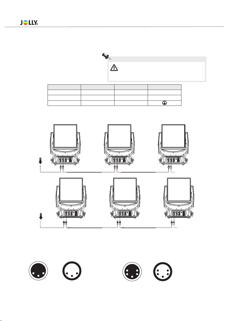
This device falls under protection class I.Therefore it is essential to connect the yellow/green conductor
to earth.
The electric connection,repairs and servicing must be carried out by a qualified employee.
Do not connect this device to a dimmer pack.
Do not switch the fixture on and off in short intervals as this would reduce the lamp’s life.
Do not touch the device’s housing bare hands during its operation(housing becomes hot)!
For replacement use lamps and fuses of same type and rating only.
t 90
c°C
IP20
t 40
a°C
Risk Gr oup 2
Accor ding to
En624 71
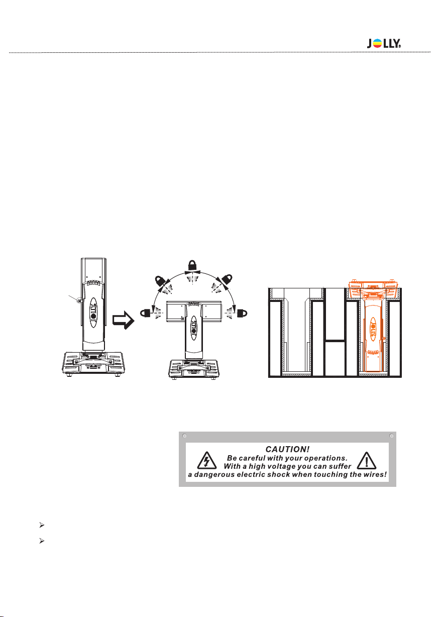
Eye damage!
Avoid looking directly into the light source(meant especially for epileptics)!
Minimum distance of illuminated objects
0.20 metres (8”) from the lens of the projector.
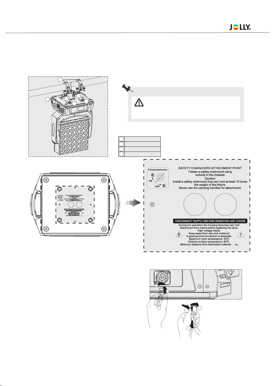
Maximum ambient temperature
Do not operate the fixture if the ambient temperatuer(Ta) exceeds 40°C (104°F).
Temperature of the external surface
The maximum temperature that can be reached on the external surface of the fitting,in a ther-
mally steadystate,is 90°C (194°F).
IP20 protection rating
The fitting is protected against penetration by solid of over 12mm (0.47”) in diameter (first
digit 2), but not against dripping water,rain,splashes or jets of water (second digit 0).
Indoor use only
Not suitable for household illumination
Photobiological Safety
CAUTION.Possibly hazardous optical radiation emitted from this product.Do not stare at
operating lamp.May be harmful to the eyes.
Light collimation system
This product contains internal light collimation system.Avoid intense light from any angle.
The products to which this manual refers comply with the European Directives purs-
uant to:
•2006/95/EC - Safety of electrical equipment supplied at low voltage (LVD)
•2004/108/EC - Electromagnetic Compatibility (EMC)
•2011/65/EU - Restriction of the use of certain hazardous substances (RoHS)
•2009/125/EC - EcoDesign requirements for Energy-related Products (ErP)
Protection against electrical shock
Connection must be made to a power supply system fitted with efficient earthing (Class I app-
liance according to standard EN 60598-1) .It is, moreover, recommended to protect the supply
lines of the projectors from indirect contact and/orshorting to earth by using appropriately
sized residual current devices.
The projector needs to be positioned so that the objects hit by the beam of light are at least
- 2 -