MEP Fire Brigade Key FSK700 Series User manual


ser Manual FSK700-2 / FSK700-2SX 3
Contents
1 Introduction...................................................................................................................................5
1.1 General............................................................................................................................................5
1.2 Description of the Series FSK700 Key Safe...................................................................................5
1.2.1 Main features of the Series FSK700 Key Safe.............................................................................6
1.3 Types of signs.................................................................................................................................7
1.4 Outline of the manual......................................................................................................................7
1.5 Abbreviations..................................................................................................................................7
1.6 Important advice for the operator and specialist installer................................................................7
1.7 Cleaning the Series FSK700 Fire Brigade Key Safe.......................................................................8
1.8 Product contents..............................................................................................................................8
1.9 Product overview............................................................................................................................9
1.10 Special terms.................................................................................................................................10
1.11 Standards, Guidelines, CE marking..............................................................................................11
1.12 Warranty.......................................................................................................................................11
2 Function........................................................................................................................................12
2.1 Normal condition..........................................................................................................................12
2.2 Fire alarm condition......................................................................................................................12
2.3 Activation of the unblocking device.............................................................................................13
2.4 Fire alarm reset.............................................................................................................................13
2.5 Sabotage alarm..............................................................................................................................13
3 Installation....................................................................................................................................14
3.1 General..........................................................................................................................................14
3.2 Installation site..............................................................................................................................14
3.3 Installation of Flush Mounting Frame EZ700-2 or Flush Mounting Frame with
Drill Protection EZBS700-2..........................................................................................................15
3.4 Installation of Flush Mounting Frame EZ700-2 or Flush Mounting Frame with
Drill Protection EZBS700-2 in Key Safe Column SDS700-2.......................................................15
3.5 Preparation of the Fire Brigade Key Safe......................................................................................15
3.5.1 Removal of the inner door angle................................................................................................16
3.5.2 Installation of a locking half cylinder in the Locking Cylinder Mounting Bracket.....................16
3.5.3 Installation of additional locking half cylinders in Key Safe FSK700-2SX................................17
3.5.4 Installation of the inner door......................................................................................................18
3.6 Installation of the Fire Brigade Key Safe in the Flush Mounting Frame.......................................19
4 Connection....................................................................................................................................20
4.1 Preparation of the connection cables.............................................................................................20
4.2 Inner view of the Fire Brigade Key Safe.......................................................................................21
4.3 Layout of Connection Board APL-4.............................................................................................21
4.4 Connecting....................................................................................................................................22
4.4.1 Complete connection diagram....................................................................................................22
4.4.2 Connecting the Flush Mounting Frame with Drill Protection, or the Tamper Switch
of the Key Safe Column.............................................................................................................24
4.4.3 Heating device of the Series FSK700 Fire Brigade Key Safe.....................................................24
4.5 Connecting the cables of the Key Safe to Connection Board APL-4............................................24
4.5.1 Ribbon cable of the outer door...................................................................................................25
4.5.2 Cable of the closure device.........................................................................................................25
4.5.3 Connecting the cables of the Locking Cylinder Mounting Brackets...........................................25
4.6 Typical connection diagram of a fire detection control panel and the Fire Brigade Key Safe.......26
4.6.1 Connection diagram of a system comprising fire detection control panel,
Series FSK700 Key Safe, Key Safe Controlling and Monitoring Device AD900-1,
and Power Supply nit NT700-1...............................................................................................26
4.6.2 Connection diagram of a system comprising fire detection control panel,
HB_FSK700_1020_9161690_Englisch_D.odt / 1022 D
ZN62163/38/3
3

4ser Manual FSK700-2 / FSK700-2SX
burglar alarm control panel, and Fire Brigade Key Safe.............................................................26
4.6.3 Connection diagram of a system comprising burglar alarm control panel and
Fire Brigade Key Safe, without fire detection control panel.......................................................27
5 Commissioning............................................................................................................................28
5.1 General..........................................................................................................................................28
5.2 Notes on insurance protection.......................................................................................................28
5.3 Configuration with jumpers..........................................................................................................28
5.3.1 Activation temperature of the outer door heating device............................................................28
5.3.2 Acoustic warning signal when missing master key....................................................................28
5.3.3 Automatic deactivation of the release magnet when outer door is open.....................................29
5.4 Commissioning instructions..........................................................................................................29
6 Inspection, maintenance, service.............................................................................................32
6.1 Inspection, maintenance................................................................................................................32
6.2 Advice on fault correction of electrical parts................................................................................33
7 Technical specifications.............................................................................................................35
7.1 Fire Brigade Key Safe FSK700-2, FSK700-2SX..........................................................................35
7.2 Inner doors....................................................................................................................................35
7.2.1 Inner Door for FSK700-2/2SX/PHZ/30.5mm ITA-2..................................................................35
7.2.2 Inner Door for FSK700-2/2SX/PHZ/35.5mm ITA-3..................................................................35
7.2.3 Inner Door for FSK700-2/2SX/DB S ITB-2.............................................................................36
7.2.4 Inner Door for FSK700-2/2SX/DB S ITF-2.............................................................................36
7.3 Flush Mounting Frames................................................................................................................36
7.3.1 Flush Mounting Frame EZ700-2................................................................................................36
7.3.2 Flush Mounting Frame with Drill Protection EZBS700-2..........................................................36
7.4 Locking Cylinder Mounting Bracket for FSK700-2SX PHZAW700-2S1....................................36
7.5 Auxiliary Locking Cylinder for FSK700-2/2SX PHZ700-2..........................................................36
7.6 Weather Protection Hood for FSK700-2/2SX WSD-FSK.............................................................36
Certifications................................................................................................................................37
8.1 VdS Certificate.............................................................................................................................37
8.2 EC Declaration of Conformity......................................................................................................38
HB_FSK700_1020_9161690_Englisch_D.odt / 1022 D / AN9161690
ZN62163/38/4
Safety Instructions
Prior to installing, operating, or providing maintenance to the products described herein,
the respective chapters of this manual must strictly be read, and especially the safety
information on page 7 and onwards in chapter 1.6 "Important advice for the operator and
specialist installer" must be implicitly observed and followed.
Furthermore, the pictographs on page 7 in chapter 1.3: "Types of signs" are highly
important – the many passages in this manual marked by these pictographs contain warn-
ings of dangers that can arise from inappropriate usage of the product, as well as other
valuable advice.
Described in this manual is the range of functions of the Fire Brigade Key Safes FSK700-2
and FSK700-2SX (combinedly termed "Series FSK700") with Connection Board APL-4
(version number PN60046V2-H005) and Door Protection Board BOHR-4 (version num-
ber PN60047V1-H002). Outer dimensions are applicable from production number
0 /06 06 onwards. The functionality of units with a different production number can dif-
fer from the description in this manual in some points.
4
ser Manual FSK700-2 / FSK700-2SX Chapter 1 • Introduction 5
1 Introduction
1.1 General
Fire Brigade Key Safes serve for the theft-proof, copy-protected safekeeping of master keys, allow-
ing the Fire Brigade to enter a building swiftly and without use of force in the event of fire.
The Fire Brigade Key Safe is installed in the entry area of the respective site. pon alarm activa-
tion of the fire detection system, the outer door is unlocked remotely by the fire brigade, granting
access to the inner door of the Key Safe.
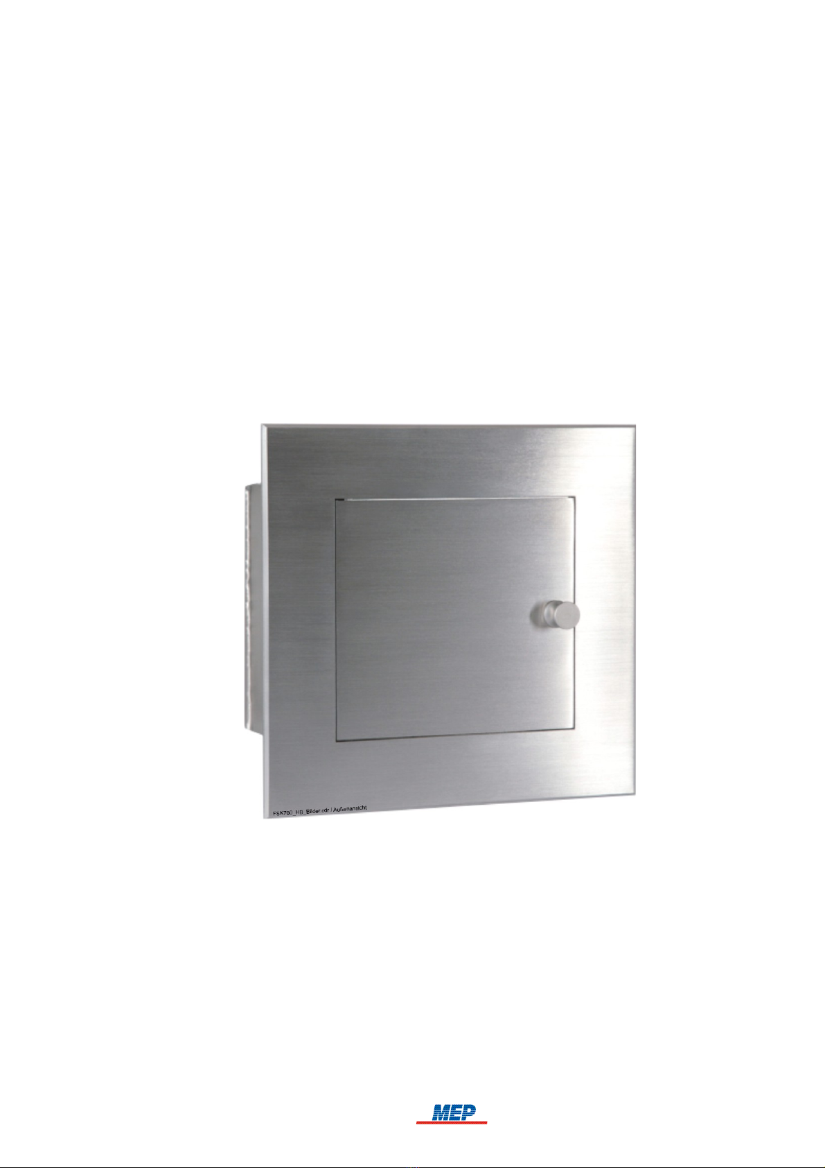
1.2 Description of the Series FSK700 Key Safe
Fire Brigade Key Safes FSK700-2 and FSK700-2SX (combinedly termed "Series FSK700"), as
manufactured by MEP-Gefahrenmeldetechnik GmbH (abbreviated "MEP" hereafter), are distin-
guished by application of solid, high-quality materials, as well as intelligent details in design,
achieving high security against unauthorised taking of master keys. Furthermore, master keys can
be secured by integrating the electric surveillance devices of the Key Safe in a burglar alarm sys-
tem.
Fig. 1: Series FSK700 Fire Brigade Key Safe – front view
Series FSK700 consists of
Key Safe FSK700-2 (MEP Article No. 265740), in which one master key can be kept,
Key Safe FSK700-2SX (MEP Article No. 265742), of which the basic version can keep up to
two master keys, and can be upgraded with two Locking Cylinder Mounting Brackets to keep a
total of four master keys,
a range of accessory parts, described in chapter 1.9: "Product overview", from page 9 onwards.
HB_FSK700_1020_9161690_Englisch_D.odt / 1022 D / AN9161690
ZN62163/38/5
5

6 Chapter 1 • Introduction ser Manual FSK700-2 / FSK700-2SX
Fig. 2: Series FSK700 Fire Brigade Key Safe
On the left: FSK700-2 with open o ter and inner doors, master key inserted, inner door fitted
with a do ble-bit variable lock
On the right: FSK700-2SX with 4 master keys, open o ter and inner doors, inner door fitted with
a lock for a locking half cylinder
1.2.1 Main features of the Series FSK700 Key Safe
The Series FSK700 Key Safe has been tested and certified (Certification No. G 199055) by VdS
Schadenverhütung GmbH (VdS). In combination with a VdS-certified Key Safe controlling and
monitoring device, it can be employed together with most commercially available 12V or 24V fire
detection and burglar alarm systems.
The Series FSK700 Key Safe conforms to DIN 14675 Appendix C – Class 3 (FSD 3, high risk).
p to four master keys can be stored inside a Fire Brigade Key Safe, thus meeting even complex
organisational requirements.
Due to intelligent details in design – for instance, protected outer door hinges – high security
against unauthorised opening is achieved.
The self-adjusting magnetic closure device automatically assumes the optimal position – therefore,
the closure device is able to function at the highest precision level, even during long-time opera-
tion under unfavourable temperatures or environmental conditions.
To guarantee high corrosion resistance and mechanical stability, all vital mechanical parts are
made from stainless steel.
Installation of the Key Safe is easy and smooth due to the Flush Mounting Frame introduced
many years ago in Germany by MEP.
An acoustic warning signal will sound from the Key Safe if not all master keys have been inserted
correctly.
For application of different locking mechanisms, such as double-bit variable locks or locking half
cylinders, suitable inner doors are available.
To assure unhindered opening of the Key Safe at low outside temperatures, the outer door can be
electrically heated with 12V or 24V AC or DC. Heating is controlled by temperature, operating
only at temperatures below +10°C (at factory default settings).
Adaption of the magnetic closure device and heating device to different voltages (12V or 24V) is
performed automatically by all Series FSK700 units, guaranteeing quick and problem-free com-
missioning.
HB_FSK700_1020_9161690_Englisch_D.odt / 1022 D / AN9161690
ZN62163/38/6
6

ser Manual FSK700-2 / FSK700-2SX Chapter 1 • Introduction 7
1.3 Types of signs
Especially important passages in this manual are marked with signs. The following signs are used:
ATTENTION! Disregard of this reference can lead to malfunction or damage to the unit.
TIP! This passage contains notes that will help ease operation.
The country-specific and/or the site-specific requirements of the device and/or system
APPROVALS must be observed.
1.4 Outline of the manual
Following the safety instructions on page 4, and guidelines given in the first chapter, which
should be implicitly observed,
chapter two contains all information required to operate a Series FSK700 Fire Brigade Key
Safe. It is explained how the Fire Brigade Key Safe works in combination with a fire detection
control panel, a controlling and monitoring device, an unblocking device, and a transmitting
device, as well as describing in which situations sabotage alarm is activated.
In chapter three, relevant guidelines for the installation of the Fire Brigade Key Safe by a spe-
cialist installer are given.
In chapter four, the specialist installer is provided with an overview of the arrangement of ter-
minals, connectors, and other important elements, as well as information required to connect
the Fire Brigade Key Safe to an MEP Key Safe Controlling and Monitoring Device AD900-1,
and to a fire detection control panel.
In chapter five, commissioning of the Fire Brigade Key Safe is described in detail for the spe-
cialist installer.
In chapter six, notes on inspection and maintenance of the unit are given. Also described in
this chapter are possible causes of malfunction and steps to correct them.
In chapter seven, all essential technical specifications of the unit are presented.
In chapter eight, copies of the VdS-Prüfzertifikat and the EC Declaration of Conformity are
provided.
1.5 Abbreviations
The correct designations for both Key Safe types "Fire Brigade Key Safe FSK700-2" and "Fire Bri-
gade Key Safe FSK700-2SX" are shortened to "Fire Brigade Key Safe", "Key Safe", or "Series
FSK700" for improved readability of the manual. Differences between the two types are noted in
the respective text passages.
1.6 Important advice for the operator and specialist installer
The keeping of keys in a Fire Brigade Key Safe results in an increased level of danger, which the
insurance company must be informed of.
If the key depot is not VdS-certified and/or is not installed, operated and maintained
according to the VdS-Richtlinien für Schlüsseldepots, Planung, Einbau und Instandhaltung
(VdS 2350), it is possible that no insurance protection is available for damages due to burg-
lary, in case the building has been opened using the (real) key taken from the key depot.
The Fire Brigade Key Safe must only be used in combination with components recommended or
certified by the manufacturer, and exclusively for the application described in the manual.
HB_FSK700_1020_9161690_Englisch_D.odt / 1022 D / AN9161690
ZN62163/38/7
7

8 Chapter 1 • Introduction ser Manual FSK700-2 / FSK700-2SX
For the safe operation of the Fire Brigade Key Safe, appropriate transport, storage, installation,
commissioning, inspection, proper maintenance and correction of malfunctions, as well as careful
and competent handling are required.
Fire detection systems and devices must, on principle, be installed by and receive maintenance
from regularly trained technical staff only. Special training for technical staff must be performed by
MEP-Gefahrenmeldetechnik GmbH (MEP) or personnel expressly authorised by MEP. Coun-
try-specific standards, rules and regulations, or instructions by MEP must be strictly abided.
For proper functioning of the fire detection system, all devices must be installed according to regu-
lations, and supplied with voltage. It must be ensured that all units are suitable to use under expec-
ted environmental conditions.
All work on the componentry of the Fire Brigade Key Safe must be performed without
voltage. Installation must be thoroughly checked prior to supplying voltage.
Regular maintenance based on country-specific standards must be performed on fire detection sys-
tems. Required repairs are to be promptly performed.
The locking bolt must only be installed in the outer door after both the Fire Brigade Key
Safe and the connected controlling and monitoring device are fully operational!
Also take note of the advice given from page 15 onwards in chapter 3.5: "Preparation of the
Fire Brigade Key Safe", as well as from page 29 onwards in chapter 5.4: "Commissioning
instructions".
1.7 Cleaning the Series FSK700 Fire Brigade Key Safe
Series FSK700 Key Safes are manufactured from stainless steel, and as such are – apart from
providing high mechanical stability – mostly corrosion-free. Residue of steel or iron (e.g., grit pro-
duced by brake discs of motorised vehicles), however, can rust and penetrate the corrosion protec-
tion layer of almost any high-grade steel – this can, after prolonged exposure, leave traces of corro-
sion on the Key Safe itself.
To prevent this, the front side of the Key Safe should regularly be cleaned using a plain, non-abras-
ive cleaning aid. Afterwards, special products for care of stainless steel should be applied to the
surface.
nder no circumstances use abrasive detergents – this would scratch the finely polished surface
of the Key Safe!
1. Product contents
Series FSK700 Key Safes are 100% tested for operation, and are supplied with all materials neces-
sary for installation, as well as a manual.
Outside the scope of delivery are Inner Doors, Flush Mounting Frames, Auxiliary Locking Cylin-
ders, Weather Protection Hood, etc. These are listed in the following chapter 1.9: "Product over-
view", must be ordered, and will be delivered separately.
HB_FSK700_1020_9161690_Englisch_D.odt / 1022 D / AN9161690
ZN62163/38/8

ser Manual FSK700-2 / FSK700-2SX Chapter 1 • Introduction 9
1.9 Product overview
The following table lists all types of Series FSK700 Fire Brigade Key Safes, as well as available
accessory parts.
•MEP Article No.
•Name
•Type
•Notes
•265740
•Fire Brigade Key Safe
•FSK700-2
•For safekeeping of one master key
•265742
•Fire Brigade Key Safe
•FSK700-2SX
•For safekeeping of two master keys, with upgrade options for up to four master keys
•265751
•Flush Mounting Frame
•EZ700-2
•For installation of Key Safe FSK700-2 or FSK700-2SX in a solid wall
•265818
•Flush Mounting Frame with All-Side Drill Protection
•EZBS700-2
•For installation of Key Safe FSK700-2 or FSK700-2SX in the Key Safe Column or
a wall with thermal insulation.
•265752
•Inner Door for FSK700-2/2SX/PHZ/30.5mm
•ITA-2
•Includes pre-installed lock for locking cylinders compliant with VdS 2156 Class B,
with a length of 30.5mm. Locking cylinder is not included!
•265748
•Inner Door for FSK700-2/2SX/PHZ/35.5mm
•ITA-3
•Includes pre-installed lock for locking cylinders compliant with VdS 2156 Class B,
with a length of 35.5mm. Locking cylinder is not included!
•265753
•Inner Door for FSK700-2/2SX/DB S
•ITB-2
•For double-bit variable lock type 2 or type 2005. Lock is not included!
•265757
•Inner Door for FSK700-2/2SX/DB S
•ITF-2
•For double-bit variable lock type Mauer 70091/70092. Lock is not included!
•265744
•Auxiliary Locking Cylinder for FSK700-2/2SX
•PHZ700-2
•Common key locking cylinder, total length 36.3mm, key bit position of 0°.
An auxiliary locking cylinder is used if special master keys (e.g., electronic keys,
transponders, etc.) are to be kept inside the Key Safe. These are inseparably
attached to the supplied key fitting the auxiliary locking cylinder using the included
quick link.
HB_FSK700_1020_9161690_Englisch_D.odt / 1022 D / AN9161690
ZN62163/38/9
9

10 Chapter 1 • Introduction ser Manual FSK700-2 / FSK700-2SX
•265743
•Locking Cylinder Mounting Bracket FSK700-2SX
•PHZAW700-2S1
•For upgrading Key Safe FSK700-2SX to be able to keep one additional master key
•249650
•Weather Protection Hood for FSK700-2/2SX
•WSD-FSK
•Offers further protection of the Fire Brigade Key Safe against humidity if rain hits
the area around the outer door from above or from the sides
Table 1: Available accessory parts for the Series FSK700 Fire Brigade Key Safe
1.10 Special terms
Several of the technical / special terms that appear in this manual are defined herein. Take further
notice of the information given in the manual of the respectively used fire detection control panel.
Unblocking device
A key switch to which public safety services (e.g., fire brigade) possess a key, installed outside
the site, and with which fire alarm can be activated from outside the site. The fire alarm will
activate the transmitting device of the fire detection control panel, thus unlocking the outer door
of the Key Safe in which the master key is kept.
Auxiliary locking cylinder
An auxiliary locking cylinder is used if special master keys inapplicable for use with a locking
cylinder (e.g., electronic keys, transponders, etc.) are to be kept inside the Fire Brigade Key
Safe. The master keys are inseparably attached to the supplied key fitting the auxiliary locking
cylinder using the included quick link.
Key depot, termed "Key Safe" in the manual
Solid two-door container, which can be unlocked remotely, used for the safekeeping of master
keys. A key depot consists of a mechanically stable case, of which the outer door can be electro-
magnetically unlocked by an unlocking device. Located inside the key depot is an inner door, to
which the key is in the possession of, e.g., the fire brigade or a security company alone. The
master keys are kept behind the inner door. The key depot, as well as the keys kept inside are
under electronic surveillance. The keys are thus protected from unauthorised access, yet quickly
reachable by the fire brigade in case of emergency.
Definition from VdS-Richtlinie 2105: "4.2.4. Key depot 3 (SD3) – equal to DIN 14675 – FSD 3.
A container installed in a solid outer wall of a building. The keys kept inside the container enable
entry to secured areas. Monitoring of the key depot is required. The key depot is connected to an
alarm detection control panel."
Key depot control
Key depot control incorporates all functions required for controlling and monitoring of a key
depot. It can be available as part of an external device (e.g., fire detection control panel), a dis-
crete module (e.g., circuit board), or a separate device.
Key depot controlling and monitoring device
Key depot control variant, available as a separate device or discrete module (e.g., a slide-in
module for an alarm system).
Transmitting device for alarm transmission
Transmitting devices receive messages from alarm systems, process them for transmission via
transmission paths, and serve as interface for these transmission paths. Furthermore, transmit-
ting devices process the commands given by the alarm receiving device and transmit them to the
connected alarm system.
HB_FSK700_1020_9161690_Englisch_D.odt / 1022 D / AN9161690
ZN62163/38/10
10

ser Manual FSK700-2 / FSK700-2SX Chapter 1 • Introduction 11
Confirmation signal
Signal transmitted to the fire detection control panel by the transmitting device, serving as con-
firmation of the successful activation of the transmitting device.
Variable lock
Lock that can be converted to use a new key code without replacing the tumblers.
1.11 Standards, Guidelines, CE marking
This manual contains dated and undated references to relevant standards. These references appear
in the appropriate sections of the manual, the titles of these standards are listed below. The latest
version of the respective standards are in effect.
DIN 14675 / App. C Fire detection and fire alarm systems - Design and operation
VdS 2105 Schlüsseldepots (SD) - Anforderungen an Anlagenteile
VdS 2350 Schlüsseldepots (SD) - Planung, Einbau und Instandhaltung
DIN 1053 Masonry
DIN 106 Calcium silicate units with specific properties
DIN 1045 Concrete, reinforced and prestressed concrete structures
DIN 49020 Conduit for Electrical Wiring; Screwed Steel Conduit, Plain Conduit,
Couplers
The CE marking on the Series FSK700 Fire Brigade Key Safe is done in accordance with Directive
2004/108/EC of the European Parliament and of the Council regarding Electromagnetic Compatib-
ility (EMC). With the CE marking, see page 38 in chapter 8.2: "EC Declaration of Conformity", the
manufacturer confirms that the product conforms to EMC Directive 2004/108/EC.
1.12 Warranty
All parts of the Series FSK700 Fire Brigade Key Safe by MEP are manufactured with highest pre-
cision and utmost care. Nonetheless, the occurrence of malfunctions during operation cannot be
ruled out entirely. To register a complaint, please contact the company responsible for installation
of your system.
While the warranty period is in effect, all parts that become defective because of a demonstrable
flaw in their manufacture or in material will be either replaced or repaired free of charge. In such
cases, the time period of the original warranty will not be extended, nor will a new warranty period
be set for the replaced or repaired parts. All further claims are excluded, especially those regarding
reductions of the purchase price, cancellation of contract, compensatory damages or replacement
due to secondary damages of any type. Beyond these regulations, the current regulations of the
"General Terms of Delivery" that are issued by the Austrian Electrical and Electronics Industry
Association are in effect.
HB_FSK700_1020_9161690_Englisch_D.odt / 1022 D / AN9161690
ZN62163/38/11
11

12 Chapter 2 • Function ser Manual FSK700-2 / FSK700-2SX
2 Function
The Series FSK700 Key Safe features independently operating sensors and actuators. The logical
operations between the signals of the sensors and actuators are made by the corresponding monitor-
ing equipment (such as Key Safe Controlling and Monitoring Device AD900-1, MEP Article No.
265900), which acts as intelligent interface between the Key Safe and the fire detection control
panel or burglar alarm system.
1) See page 13 onwards in chapter 2.4: "Fire alarm reset"
2) With integrated temperature-controlled panel heating
3) With one master key
4) With double-bit variable lock and inserted key
Fig. 3: Fire Brigade Key Safe FSK700-2, displayed with doors open
2.1 Normal condition
The Fire Brigade Key Safe is in normal condition if:
the master key/all master keys are inserted correctly,
the inner door is closed,
the key to the inner door has been removed,
the outer door is closed, and
the unlocking device of the Key Safe has not been activated.
In normal condition, the electromagnet of the outer door closure device is rendered currentless.
2.2 Fire alarm condition
Fire alarm is reported to the fire brigade by the fire detection control panel using a transmitting
device. The fire brigade will transmit the confirmation signal, which, via the controlling and monit-
oring device, electromagnetically unlocks the outer door of the Key Safe – the outer door is thereby
cleared for opening.
The outer door does not open automatically after unlocking.
After opening the outer door, the inner door can be accessed. sing the key in possession of the fire
brigade, the inner door can be opened, and the master key(s) obtained.
In this state, monitoring of opening or sabotage of the Key Safe, as well as – if available – monit-
oring of the Flush Mounting Frame with Drill Protection and the Key Safe Column is disabled.
In special application cases, unlocking of the outer door must only be performed when, supple-
mentary to the confirmation signal, the fire detection control panel is in fire alarm condition. The
Key Safe Controlling and Monitoring Device AD900-1 by MEP is equipped for this special
application, featuring two unlocking inputs, which can be connected via a logical AND operation
(AD900-1 / S2-1 switched "ON").
HB_FSK700_1020_9161690_Englisch_D.odt / 1022 D / AN9161690
ZN62163/38/12
12

ser Manual FSK700-2 / FSK700-2SX Chapter 2 • Function 13
2.3 Activation of the unblocking device
The unblocking device (a specially realised key switch – see, for example, nblocking Device
FSE/PHZ900-1, MEP Article No. 265662) is connected to the fire detection control panel in the
same way as a manual call point. pon activation of the unblocking device, fire alarm will be
activated, thus unlocking the outer door of the Fire Brigade Key Safe via the confirmation signal of
the transmitting device connected to the fire brigade.
Activation of the fire detection control panel by the unblocking device must not affect Fire Con-
trol procedures of the fire detection control panel.
2.4 Fire alarm reset
The outer door of the Key Safe will only lock again after the fire detection control panel is reset,
thereby terminating the confirmation signal, the/all master keys have been reinserted, and the inner
and outer door have been closed. Successful locking can be confirmed by pulling the outer door.
By locking the outer door, monitoring of opening or sabotage of the Key Safe, as well as – if
available – monitoring of the Flush Mounting Frame with Drill Protection and the Key Safe
Column will be reactivated.
Should a master key not have been inserted correctly after resetting the fire detection control panel,
a sustained buzzing tone generated by the Key Safe's integrated buzzer will sound upon closing the
outer door.
This function is only available if the Key Safe is connected to the Key Safe Controlling and
Monitoring Device AD900-1 by MEP (also see page 28 and onwards in chapter 5.3.2: "Acoustic
warning signal when missing master key").
If the Key Safe remains unopened during fire alarm, the outer door will be automatically locked
again upon termination of the confirmation signal, and monitoring of opening or sabotage of the
Key Safe, as well as – if available – monitoring of the Flush Mounting Frame with Drill Protection
and the Key Safe Column will be reactivated.
2.5 Sabotage alarm
The following states are constantly monitored by the Key Safe Controlling and Monitoring Device
AD900-1:
Outer door closed,
Drill Protection Board undamaged,
master keys correctly inserted,
Drill Protection of the Flush Mounting Frame undamaged (if available),
Tamper Switch of the Key Safe Column closed (if available).
The Key Safe Controlling and Monitoring Device AD900-1 will generate an alarm signal if – e.g.,
by forcefully breaking into the Key Safe – one of these monitored states is violated insofar as caus-
ing the monitor loop's resistance to deviate more than 40% from normal condition.
DIN 14675 / chapter C.2.2.3: The report (sabotage report) must, under application according to
Class FSD 3 (high risk), be forwarded to an office or authority that is available at all times, such
as a police department or security company.
If the Key Safe has been unlocked by the confirmation signal, sabotage monitoring is disabled
until a reset is performed correctly (see page 13 and onwards in chapter 2.4: "Fire alarm reset").
HB_FSK700_1020_9161690_Englisch_D.odt / 1022 D / AN9161690
ZN62163/38/13
13

14 Chapter 3 • Installation ser Manual FSK700-2 / FSK700-2SX
3 Installation
3.1 General
Installation and commissioning of the Series FSK700 Fire Brigade Key Safe is to be performed by
a specialist company trained and authorised by MEP-Gefahrenmeldetechnik GmbH or their local
representative. All relevant standards and regulations must thereby be observed (see page 11 and
onwards in chapter 1.11: "Standards, Guidelines, CE marking").
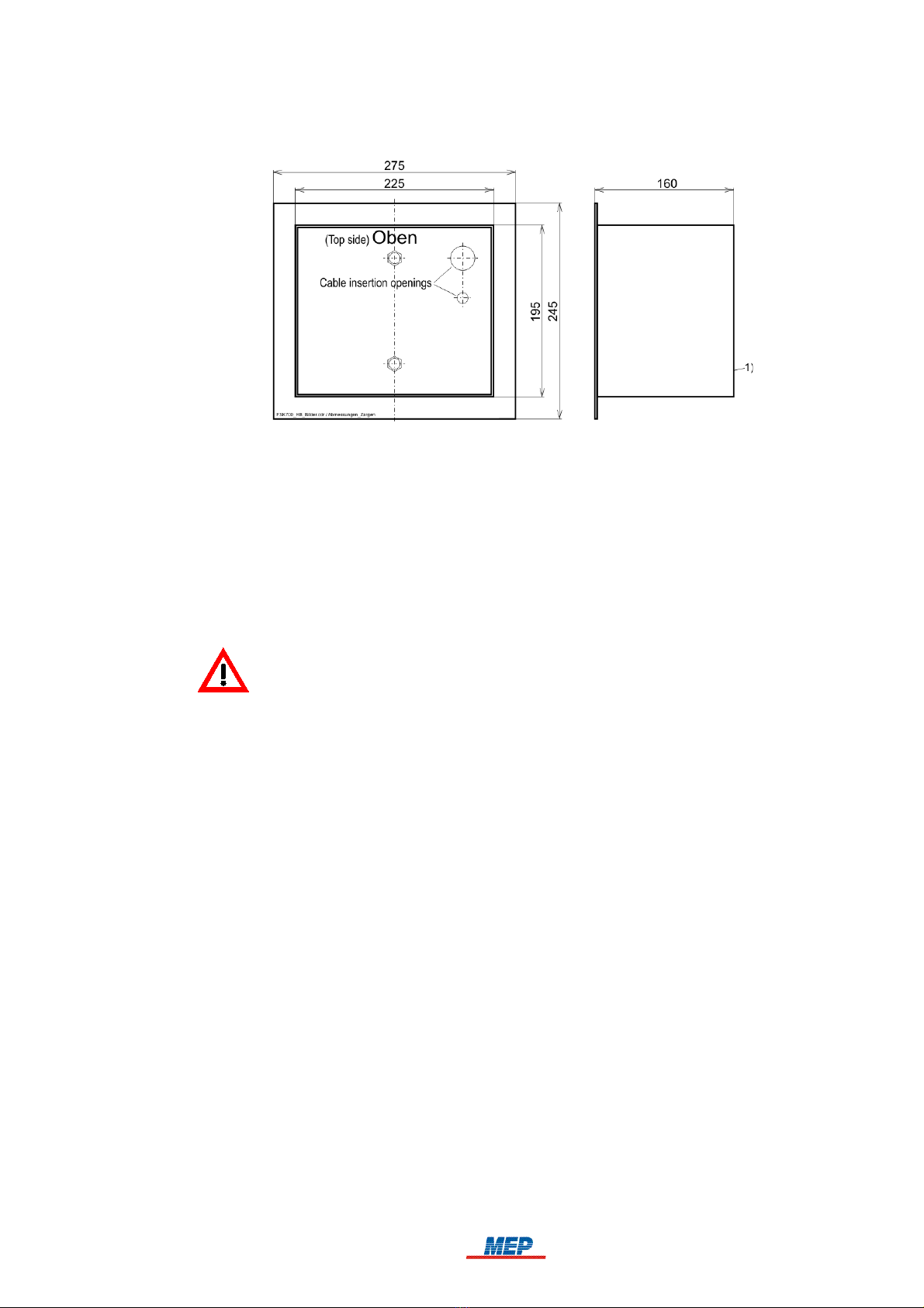
1) Optional Weather Protection Hood WSD-FSK
Fig. 4: Dimensions of the Series FSK700 Key Safe, starting from prod ction n mber 08/06806
The Key Safe is to be inserted in the Flush Mounting Frame EZ700-2, MEP Article No. 265751,
which must be tightly grounded in the wall. Should the wall not be sufficiently solid (see page 14
and onwards in chapter 3.2: "Installation site"), the Flush Mounting Frame with Drill Protection
EZBS700-2, MEP Article No. 265818 must be utilised instead.
Instructions for installation of the Key Safe in the Key Safe Column SDS700-2 are provided in
the manual "Key Safe Column SDS700-2" by MEP-Gefahrenmeldetechnik GmbH.
Controlling and monitoring of the Key Safe must be performed using a VdS-certified controlling
and monitoring device (such as Key Safe Controlling and Monitoring Device AD900-1, MEP Art-
icle No. 265900).
Instructions for installation of the controlling and monitoring device are provided in the manual
of the respectively used device.
3.2 Installation site
The Key Safe is to be installed in accordance with the local fire brigade, preferably in a weather-
proof location (i.e., in an alcove, passageway, or under a canopy), flush mounted in the wall. The
bottom edge of the Key Safe should be located about 1.2m (at least 0.8m) above the floor.
The wall in which the Key Safe (i.e., Flush Mounting Frame EZ700-2) is to be installed in must be
made from stone work according to DIN 1053, bricks according to DIN 105, lime-sand bricks
according to DIN 106, or from reinforced concrete (minimum B 25 according to DIN 1045). The
wall must be at least 80mm thicker than the installation depth of the Key Safe.
Should no adequately solid wall suitable for installation of the Key Safe be available (e.g., only
walls with thermal insulation), the Flush Mounting Frame with Drill Protection EZBS700-2 must
be utilised to improve security and protect against sabotage.
HB_FSK700_1020_9161690_Englisch_D.odt / 1022 D / AN9161690
ZN62163/38/14
14
ser Manual FSK700-2 / FSK700-2SX Chapter 3 • Installation 15
3.3 Installation of Flush Mounting Frame EZ700-2 or Flush Mounting Frame with
Drill Protection EZBS700-2
1) The front edge of the Flush Mounting Frame must not protrude from the wall
Fig. 5: Dimensions of Fl sh Mo nting Frames EZ700-2 and EZBS700-2
The front edge of the Flush Mounting Frame must be flush-mounted to the wall surface (under no
circumstances must it protrude!) as best as possible. The bottom edge of the Key Safe should be
located about 1.2m (at least 0.8m) above the floor.
Installation of Flush Mounting Frames EZ700-2 and EZBS700-2 is to be performed according to
the manual provided with the Flush Mounting Frames.
Insert the Flush Mounting Frame into the prepared opening in the wall, and insert the conduits
for the connection cables, as well as for the protective earth into the Flush Mounting Frame
from behind.
Notice the required installation position (labelled: "OBEN / TOP SIDE – Einbauzarge
putzbündig einmauern!").
Fix the Flush Mounting Frame onto the installation surface.
Fill the remaining openings in the Flush Mounting Frame, as well as the inner space with suit-
able materials, to prevent mortar, cement, or similar from entering while setting the Flush
Mounting Frame into the wall.
Protect the drill protection film inlaid in the Flush Mounting Frame with Drill Protection EZB-
S700-2, and the connection cable from damage while setting the Flush Mounting Frame into the
wall.
Fix the Flush Mounting Frame in the wall.
3.4 Installation of Flush Mounting Frame EZ700-2 or Flush Mounting Frame with
Drill Protection EZBS700-2 in Key Safe Column SDS700-2
Instructions for installation in the Key Safe Column SDS700-2, with or without cement grouting
according to VdS guidelines 2105 and 2350, are found in the manual "Key Safe Column
SDS700-2" by MEP-Gefahrenmeldetechnik GmbH.
3.5 Preparation of the Fire Brigade Key Safe
The Series FSK700 Fire Brigade Key Safe must be fitted with the appropriate inner door, as well as
the locking cylinder(s) for the master key(s) or auxiliary locking cylinder(s). Installation of addi-
tional Locking Cylinder Mounting Brackets PHZAW700-2S1 along with appropriate locking cylin-
ders is required for the Series FSK700-2SX Key Safe if more than two master keys are to be kept.
It is possible to perform the following tasks on an already installed Key Safe – however, it is
recommended to complete preparation of the Key Safe before installation in the Flush Mounting
Frame.
HB_FSK700_1020_9161690_Englisch_D.odt / 1022 D / AN9161690
ZN62163/38/15
15
16 Chapter 3 • Installation ser Manual FSK700-2 / FSK700-2SX
The locking bolt supplied in the accessory kit must only be installed in the outer door after
both the Fire Brigade Key Safe and the connected controlling and monitoring device are
fully operational! Should the electrical unlocking device not be fully operational upon clos-
ing the outer door with installed locking bolt, the Key Safe can only be opened again by
means leading to the destruction of some of its componentry (e.g., outer door, Drill Protec-
tion Board). Additional advice can be found on page 29 and onwards in chapter 5.4: "Com-
missioning instructions".
3.5.1 Removal of the inner door angle
For the tasks of installing the Fire Brigade Key Safe in the Flush Mounting Frame, setting up cable
connections, as well as for the installation of the locking cylinder(s) for the master key(s), the inner
door angle must be removed.
Removal of the inner door angle is to be performed as follows:
Open the outer and inner doors.
Remove all master keys.
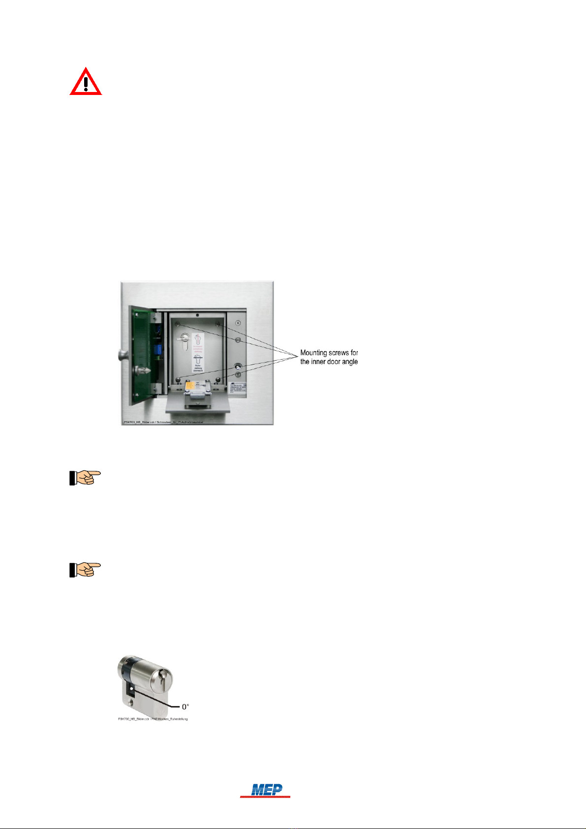
Remove the 4 mounting screws on the inner door angle (see Fig. 6 below).
Pull out the inner door angle in a forward direction.
Fig. 6: Location of the mo nting screws for the inner door angle
The fig re shows an already installed locking cylinder for the master key, as well as an inner
door incl ding lock – these parts are not pre-installed in a newly shipped Key Safe!
Reinstallation of the inner door after completion of the planned tasks is to be performed with the
steps in reverse order.
3.5.2 Installation of a locking half cylinder in the Locking Cylinder Mounting Bracket
Depending on the case of application, either a locking half cylinder identical to the locking mech-
anisms used on-site, or alternatively, an auxiliary locking cylinder (see page 10 and onwards in
chapter 1.10: "Special terms") must be installed.
Locking cylinders that meet the requirements listed in the technical specifications on page 35 and
onwards in chapter 7.1: "Fire Brigade Key Safe FSK700-2, FSK700-2SX" are to be used exclus-
ively.
Remove the inner door angle, see page 16 and onwards in chapter 3.5.1: "Removal of the inner
door angle".
Adjust the locking cam of the locking half cylinder so that it points downwards when assuming
the key removal position, see Fig. 7 below.
Fig. 7: Position of the locking cam with key removed
Insert the locking half cylinder into the Locking Cylinder Mounting Bracket and fix it in place
using the M5×12mm hex head screw included in the accessory kit.
HB_FSK700_1020_9161690_Englisch_D.odt / 1022 D / AN9161690
ZN62163/38/16
16

ser Manual FSK700-2 / FSK700-2SX Chapter 3 • Installation 17
Check the detent and proper triggering of the micro switch by the locking cam.
Check if the label showing the key removal position, found on the inner door angle, conforms
with the installed locking half cylinder for the master key. An alternative label showing a hori-
zontal key removal position is included in the accessory kit of the Key Safe, see Fig. 8 below.
Fig. 8: Label showing key removal position of the locking half cylinder designated for the master key
(key removal position on top)
On the left: factory defa lt label
On the right: alternative label showing horizontal key removal position
3.5.3 Installation of additional locking half cylinders in Key Safe FSK700-2SX
Fire Brigade Key Safe FSK700-2SX is factory-equipped with two Locking Cylinder Mounting
Brackets. sing the supplementary Locking Cylinder Mounting Brackets PHZAW700-2S1, Key
Safe FSK700-2SX can be upgraded to up to four locking half cylinders.
A Locking Cylinder Mounting Bracket PHZAW700-2S1 is required for every additional locking
half cylinder.
Key Safe type FSK700-2 is not applicable for installation of additional locking half cylinders.
Installation is to be performed as follows:
Remove the inner door angle, see page 16 and onwards in chapter 3.5.1: "Removal of the inner
door angle".
Adjust the locking cam of the locking half cylinder so that it points downwards when assuming
the key removal position, see Fig. 7 above.
Insert the locking half cylinder into the Locking Cylinder Mounting Bracket and fix it in place
using the M5×12mm hex head screw included in the accessory kit.
Install the Locking Cylinder Mounting Bracket including locking half cylinder in the next avail-
able install position, see Fig. 9 below, left-hand picture. The required M4 nuts are included in
the accessory kit of the Locking Cylinder Mounting Bracket.
The cables leading from the Locking Cylinder Mounting Brackets should only be connected to
the Connection Board after all cables leading from the controlling and monitoring device have
been connected. See page 25 and onwards in chapter 4.5.3: "Connecting the cables of the Lock-
ing Cylinder Mounting Brackets".
HB_FSK700_1020_9161690_Englisch_D.odt / 1022 D / AN9161690
ZN62163/38/17
17

18 Chapter 3 • Installation ser Manual FSK700-2 / FSK700-2SX
Fig. 9: Arrangement of locking half cylinders for master keys in Key Safe FSK700-2SX
On the left: install positions for 4 Locking Cylinder Mo nting Brackets in Key Safe
FSK700-2SX
On the right: breaking points for locking half cylinders 3 and 4 on the inner door angle
The appropriate breaking point for every additional locking half cylinder must be opened up on
the inner door angle, for example, using a flat chisel and applying a few soft hammer blows.
3.5.4 Installation of the inner door
All installation materials required for installation are included in the accessory kit provided with
the respective inner door.
Installation of the inner door can be performed more easily after removing the inner door angle
(see page 16 and onwards in chapter 3.5.1: "Removal of the inner door angle").
The locking mechanism to be used in the inner door (i.e., locking half cylinder, variable lock) is
to be determined by local authorities.
Install the variable lock in the inner door, or, with inner doors ITA-2 an ITA-3, insert the lock-
ing half cylinder into the lock and fix it using an M5×65mm countersunk head screw, see Fig.
10 below, right-hand picture (detail "A").
Fix the inner door on the inner door angle using two M4×6mm screws, see Fig. 10 below, left-
hand picture (detail "B"). The shaped recesses in the door bearings must face the inner door.
Fig. 10: Installation of the inner door
On the left: detail "A": Screw fixing the locking half cylinder in Inner Doors ITA-2 and ITA-3
detail "B": Fixing the inner door to the door bearings
detail "C": Screw sed for limiting the angle of rotation
On the right: View of the inner door angle from behind/above. The clearance of the locked inner
door is adj sted with the M5 gr b screw on the door stop bar. Fix the adj stment setting sing
the M5 co nter n t.
Insert the M5 grub screw in the upper door stop bar of the inner door angle, but tighten it only
as much so that sufficient clearance is guaranteed when the inner door is closed (see Fig. 10
above, right-hand picture).
HB_FSK700_1020_9161690_Englisch_D.odt / 1022 D / AN9161690
ZN62163/38/18
1

ser Manual FSK700-2 / FSK700-2SX Chapter 3 • Installation 19
Fix the position of the grub screw using the M5 nut included in the accessory kit.
For inner doors equipped with a locking half cylinder (ITA-2 and ITA-3), an M3×20 screw
must be used after installing the locking cylinder to limit the angle of rotation (see Fig. 10
above, right-hand picture, detail "C"), so the key cannot be removed when in unlocked position.
Afterwards, verify the proper functioning of the locking mechanism.
3.6 Installation of the Fire Brigade Key Safe in the Flush Mounting Frame
Connect the protective earth to the spot marked by the earthing symbol on Flush Mounting
Frame EZ700-2 or EZBS700-2.
Insert the cable lead-throughs included in the accessory kit of the Key Safe in the two desig-
nated openings in the back wall of the Key Safe.
Remove the inner door angle from the Key Safe (see page 16 and onwards in chapter 3.5.1:
"Removal of the inner door angle").
Insert the Key Safe into the Flush Mounting Frame, at the same time insert the cable leading
from the controlling and monitoring device through the upper cable lead-through, and – if avail-
able – insert the cable connecting the Drill Protection of Flush Mounting Frame EZBS700-2, as
well as the Tamper Switch of the Key Safe Column through the lower cable lead-through in the
back wall of the Key Safe.
Be careful that
- the cable(s) do not get crushed between the back wall of the Key Safe and the Flush Mounting
Frame, and
- the componentry inside the Key Safe does not get damaged during inserting the cables!
Fix the Key Safe in the Flush Mounting Frame using the M10 nuts, washers, and toothed lock
washers included in the accessory kit of the Flush Mounting Frame.
Tighten the nuts only as much so that the Key Safe is properly secured to the installation wall,
without deforming the base of the Flush Mounting Frame.
If the application of the Weather Protection Hood is indicated by weather conditions, the
Weather Protection Hood must be installed before fixing the Key Safe to the wall. Insert the
Weather Protection Hood from above, between the wall, or Key Safe Column, respectively, and
the door frame of the Key Safe, and fix it using M10 nuts. Be careful not to damage the cellular
rubber strips attached to the back sides of the Weather Protection Hood and the door frame.
Fig. 11: Fixing the Key Safe (example: FSK700-2SX, able to keep fo r master keys) into the Fl sh
Mo nting Frame
Detail "A": N ts for fixing the Locking Cylinder Mo nting Bracket in Key Safe FSK700-2, or the
L-bracket with Locking Cylinder Mo nting Brackets in Key Safe FSK700-2SX, respectively. See
page 22 and onwards in chapter 4.4: "Connecting".
HB_FSK700_1020_9161690_Englisch_D.odt / 1022 D / AN9161690
ZN62163/38/19
19

20 Chapter 4 • Connection ser Manual FSK700-2 / FSK700-2SX
4 Connection
The locking bolt supplied in the accessory kit must only be installed in the outer door after
both the Fire Brigade Key Safe and the connected controlling and monitoring device are
fully operational! Should the electrical unlocking device not be fully operational upon clos-
ing the outer door with installed locking bolt, the Key Safe can only be opened again by
means leading to the destruction of some of its componentry (e.g., outer door, Drill Protec-
tion Board). Additional advice can be found on page 29 and onwards in chapter 5.4: "Com-
missioning instructions".
The connection between the controlling and monitoring device and the Fire Brigade Key Safe is to
be made continuously, as well as preferably in-wall, or protected by other means.
Before beginning to make the connections, disconnect the cables connected to Connection Board
APL-4 (closure device, Locking Cylinder Mounting Bracket, etc.), to gain additional working
space.
4.1 Preparation of the connection cables
The cables inserted through the back side of the Fire Brigade Key Safe are to be prepared as fol-
lows:
Trim the connection cable leading from the controlling and monitoring device to a length of
approximately 60cm (measured from the cable insertion opening).
The cables leading from the Drill Protection of Flush Mounting Frame EZBS700-2, as well as
those leading from the Tamper Switch of the Key Safe Column are not to be trimmed. The
excess length of these cables can be housed in the hollow space between the Flush Mounting
Frame and the Key Safe (approx. 17mm).
Strip off 15cm of the insulation of the cable leading from the controlling and monitoring device.
The cables leading from the Drill Protection of Flush Mounting Frame EZBS700-2, as well as
those leading from the Tamper Switch of the Key Safe Column have already been prepared
accordingly.
If a cable with a large outer diameter is used to connect the controlling and monitoring device,
it is suggested to strip the insulation off the cable (starting at the cable insertion opening), to
ensure the small bending radius required inside the Key Safe can be achieved.
Insert the cables into the Key Safe according to Fig. 12 below, and fix the cables in place using
the nylon cable clamp located right below the Connection Board.
HB_FSK700_1020_9161690_Englisch_D.odt / 1022 D / AN9161690
ZN62163/38/20
20
This manual suits for next models
2
Table of contents


