Meraki MX600 User manual
Meraki MX600 Installation Guide
This document describes how to install and set up the MX600
security appliance. Additional reference documents are available
online
at: www.meraki.com/library/products.
MX600 Overview
The Meraki MX600 is an enterprise security appliance designed for
data
-center deployment for distributed networks that require remote
administration
. It is ideal for network administrators who demand
both ease of deployment and a state
-of-the-art feature set. The
MX600 appliance provides the following new features:
Four bypass (fail
-to-wire) ports for passthrough mode
USB port, to support approved 3G/
4G cards for failover to cellular
networks.
1 TByte cache storage for WAN acceleration.
Support for two interface modules. Each module can have either eight
1Gbit RJ45 or SFP ports or two 10Gbit SFP+ ports.
LAN 2 port can be configured to be a LAN or WAN
connection,
allowing support up to 2 WAN connections.
Dedicated management port.
Rail-kit for rack mounting
1. MX600 Overview
2. Package contents
oThe MX600 front panel
oPorts and Status Indicators
oUsing MX Expansion Slots and
Modules
oThe MX600 back panel
oMounting hardware
oSafety guidelines
3. Connecting to WAN
oSetting up a static IP address
oSetting up a DHCP IP address
oAdditional settings
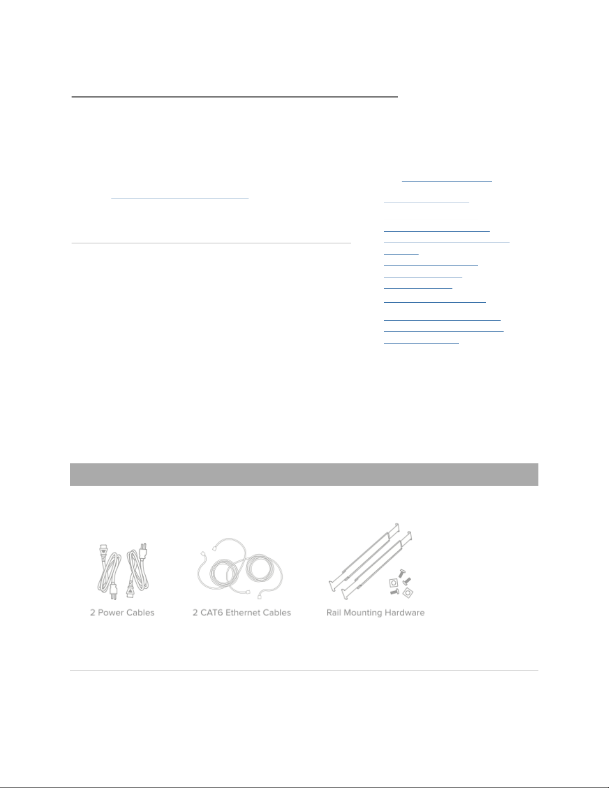
Package contents
In addition to the MX600, the following are provided.
The MX600 front panel

Ports and Status Indicators
The MX600 uses LEDs to inform the user of the device's status. When the device powers on, all the Internet LEDs
flash twice. Additional functions are described below, from left to right.
Item
Function
LED Status
Meaning
1
Power
Solid orange
Power is applied
Flashing green
Operation in progress
Solid green
Fully operational
2
Warning
Off
During boot or no USB link
Orange
Device requires attention.
Dashboard will contain additional information
3
Disk status
Off
No disk activity
Orange
Requires attention
Green
Disk activity
4
Bypass status
Off
WAN and LAN ports are separated
Green
WAN and LAN ports are connected through virtual wire
Additional functions on the front panel are described below, from left to right.
Reset button
Insert a paper clip if a reset is required.
A brief, momentary press: To delete a downloaded configuration and reboot.
Press and hold for more than 10 sec: To force the unit into a full factory reset.
USB port
USB 2.0 for 3G/4G wireless cards. Traffic status is indicated by the USB LED.
Interface
modules 1 - 2
Interface modules for extended connectivity.
SFP Combo
ports
For optional SFP-SX (fiber) or SFP-TX (RJ45 copper) GbE connectivity. The functionality of
ports 8 and 8F, and ports 9 and 9F, is mutually exclusive. Only one port of a pair is supported at a
time.
Using MX Expansion Slots and Modules
The MX600 has 2 expansion slots which can accept the following Meraki Interface Modules:
•IM-8-CU-1GB: Meraki 8 x 1 GbE Copper Interface Module for MX400 and MX600.
•IM-8-SFP-1GB: Meraki 8 x 1 GbE SFP Interface Module for MX400 and MX600.
•IM-2-SFP-10GB: Meraki 2 x 10 GbE SFP+ Interface Module for MX400 and MX600.
When replacing an interface module, Meraki-certified technician must follow the steps below:
1. Power down the MX600. Interface Modules are not hot-swappable.
2. Insert the new interface module or modules.
3. Power up the MX600.
4. Dashboard will automatically recognize the new module or modules.
Interface Modules should only be added, replaced, or removed by a Meraki-certified technician.Failure to follow the
process above will corrupt the unit and void warranty!
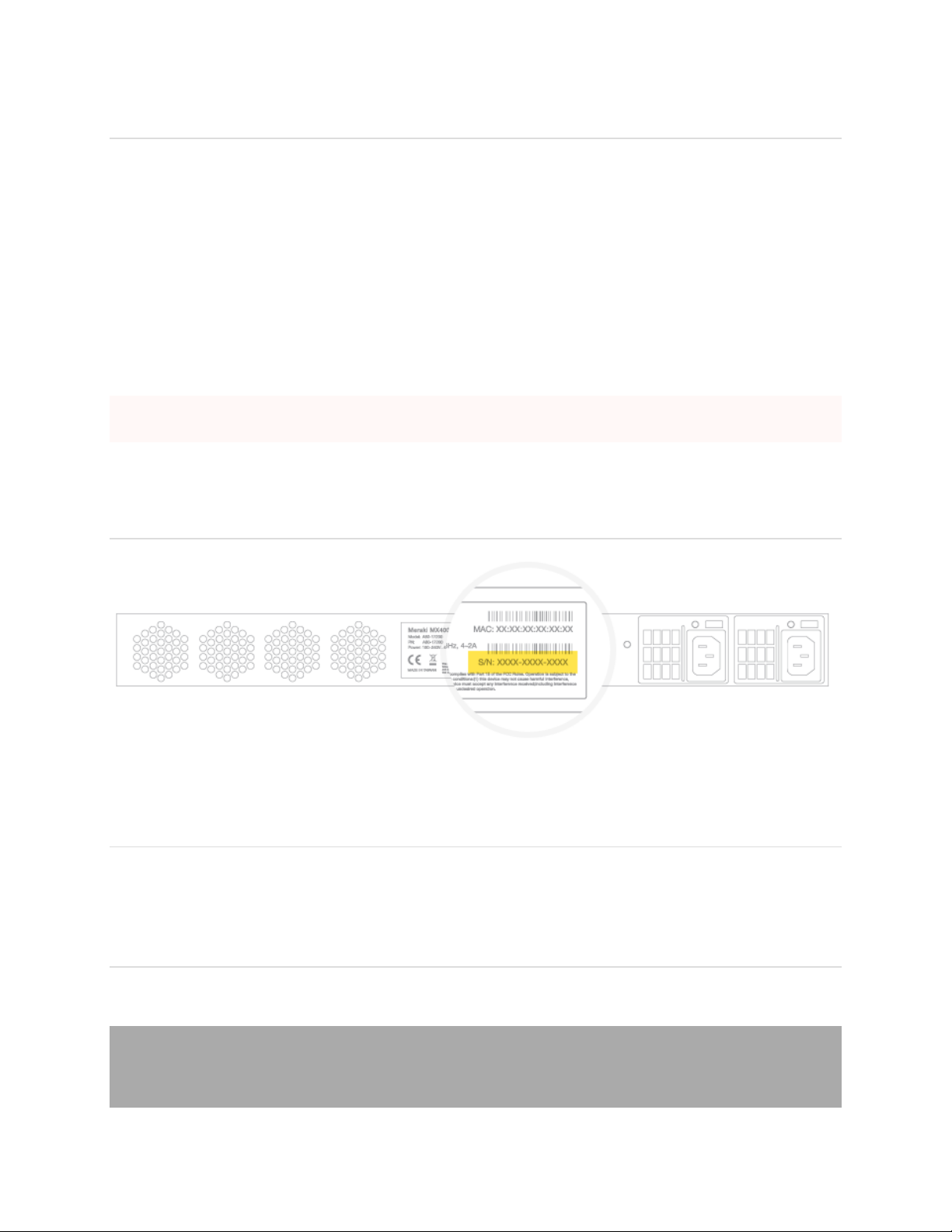
The MX600 back panel
Please note that the serial number is located on the product label at the back panel of MX600.
Mounting hardware
The mounting hardware includes a rack mount rail kit. When installing the device, make sure that there is sufficient
space between the rear of the rack and other obstacles to ensure adequate airflow.
Safety guidelines
Regardless if you are using a wall power outlet (MAINS) or any other type of power connection (e.g., a UPC
device), always ensure that the power cord can be readily disconnected from the hardware unit.
Connecting to WAN

All Meraki MX devices must have an IP address. This section describes how to configure your local area network
before you deploy it. A local management web service, running on the appliance, is accessed through a browser
running on a client PC. This web service is used for configuring and monitoring basic ISP/WAN connectivity.
Setting up a static IP address
To ensure that the client PC is redirected to the local web service in the following step, you must disable all
other network services (ex: wi-fi) on your client machine.
Do the following to configure basic connectivity and other networking parameters:
1. Using a client machine such as a laptop, connect to the management port of the MX.
2. Using a browser on the client machine, access the appliance's built-in web service by browsing
to http://setup.meraki.com. (You do not have to be connected to the Internet to reach this address)
3. Click Uplink configuration under the Local status tab.
4. Choose Static for the IP Assignment option.
5. Enter the IP address, subnet mask, default gateway IP and DNS server information.
Setting up a DHCP IP address
By default all MX devices are configured to DHCP from upstream WAN / ISP servers. Simply plug the MX's WAN
/ Internet port to your upstream circuit and wait a few minutes for the unit to negotiate a DHCP address.
When the WAN connection is fully enabled, Internet LED will turn green.
Additional settings
Please note that all these settings below are accessible only via the local management console.
Setting VLANs
If your WAN uplink is on a trunk port, choose VLAN tagging > Use VLAN tagging and enter the appropriate
value for VLAN ID for your network.
Setting up secondary WAN interface (dual WAN)
You can toggle the LAN2 port between LAN and Internet, through Uplink configuration under the Local
status tab.
Setting PPPoE
PPPoE authentication may be required if you are connecting MX device to a DSL circuit. You need to know your
authentication option and credentials (supplied by your ISP) in order to complete these steps.

•Choose Connection Type > PPPoE.
•Select your Authentication option.
•If you select Use authentication, enter appropriate values for Username and Password.
Web proxy settings
These settings take effect if the MX device has to fall back to using HTTP to contact the Cloud Controller. By
default, web proxy is disabled. To enable web proxy, do the following:
•Choose Web proxy > Yes.
•Enter values as appropriate for Hostname or IP and Port.
•If you require authentication, choose Authentication > Use authentication, and enter appropriate values
for Username and Password.
To apply all configuration settings to the appliance, be sure to click Save Settings at the bottom of the page.
Configuring physical link settings
To configure physical link settings on the Ethernet ports, click Local status > Ethernet configuration. You can
enable half duplex, full duplex, and autonegotiation, as well as set 10- or 100-Mbps data rates.
Additional safety instructions
IT Power Systems: This product is also designed for IT power distribution system with phase-to-phase
voltage 230V.
Motherboard Lithium Battery Statement: RISK OF EXPLOSION IF BATTERY IS REPLACED BY AN
INCORRECT TYPE. DISPOSE OF USED BATTERIES ACCORDING TO BATTERY INSTRUCTION.
Mutiple Power Source Warning: CAUTION: THIS UNIT HAS MORE THAN ONE POWER SUPPLY
CORD. DISCONNECT BOTH POWER SUPPLY CORDS BEFORE SERVICING TO AVOID ELECTRIC
SHOCK.
Rack Mount Instructions: Please see the following pages for installation of King Rail
098W000300001/3C02-610APZZ0LG.

Rack Mounting Installation Guide
This Rack mounting Installation guide is for Lanner’s Network security Barebone. No
matter the deminsion is 1U or 2U size. It is suitable for FW-7655, FW-7660, FW-7850,
FW-7860, FW-7870, FW-7880, FW-7890.
Make sure that the bracket and extension slide kits is in the packing (Four L- brackets
and two sliding rails). In addition, the sliding rails have 3 segments and we define
them as segment 1 (Inner Rail), segment 2 (Center Slide), segment 3 (Inner Slide).
Step 1: In this step, pull the inner slide out (Segment 3).
Step 2: Than, screw the inner slide to attach a side of the system.
A B C
A B
L-brackets
Sliding rail
Inner Slide
Center Slide
Inner Rail
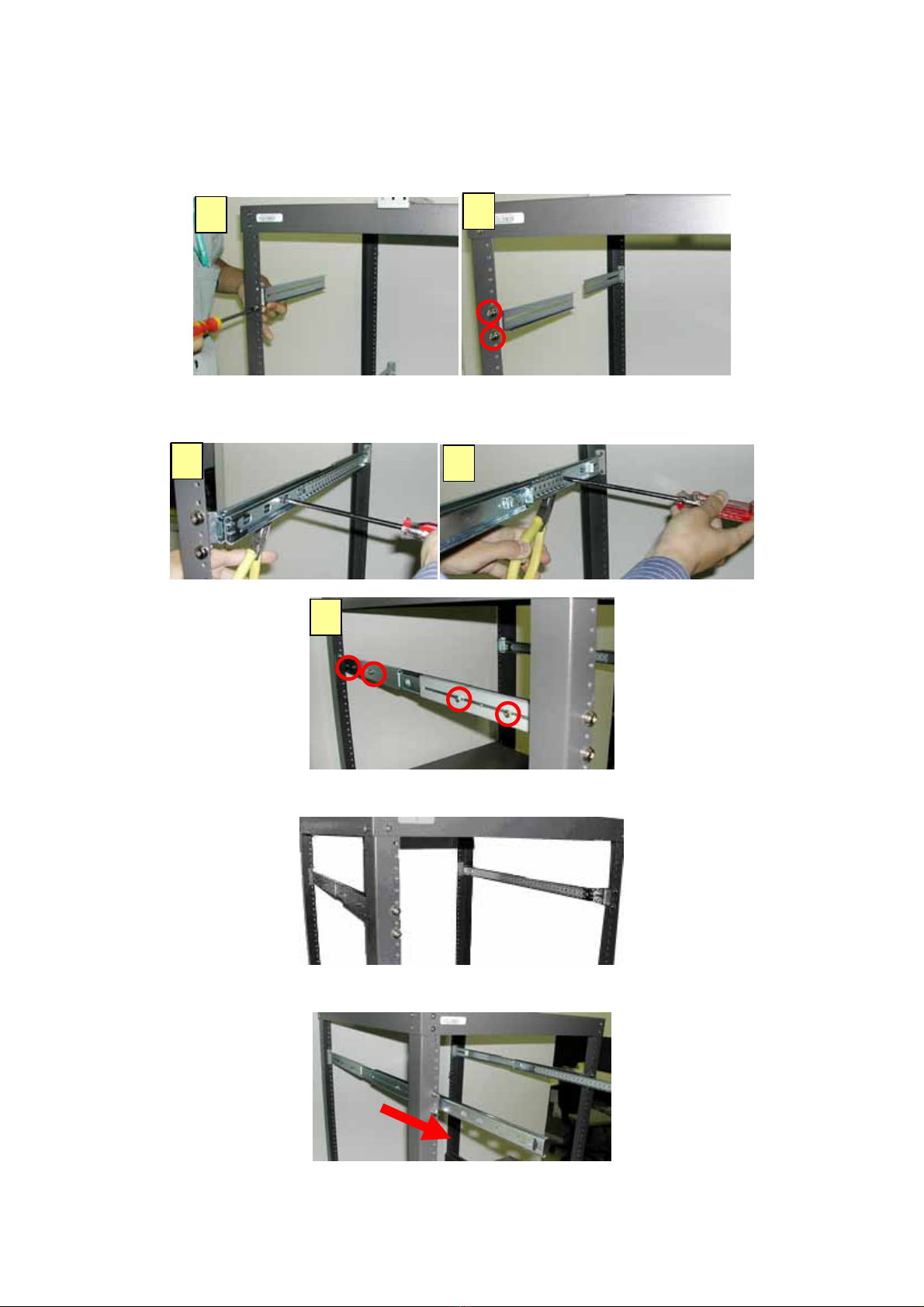
Step 3: Install those four L-brackets to the each corner of the rack.
Step 4: A. Screw the center slide together with the inner rail.
B. Pull out the center slide and attach another screw with the inner rail
Step 5: A complete installation of the sliding kits for the rack is as the below graph.
Step 6: Pull out the center rail.
Step 7: Push the whole system with the inner slide to the center slide.
A B
A B
C

Step 8: The complete installation is as the below graph.
A B
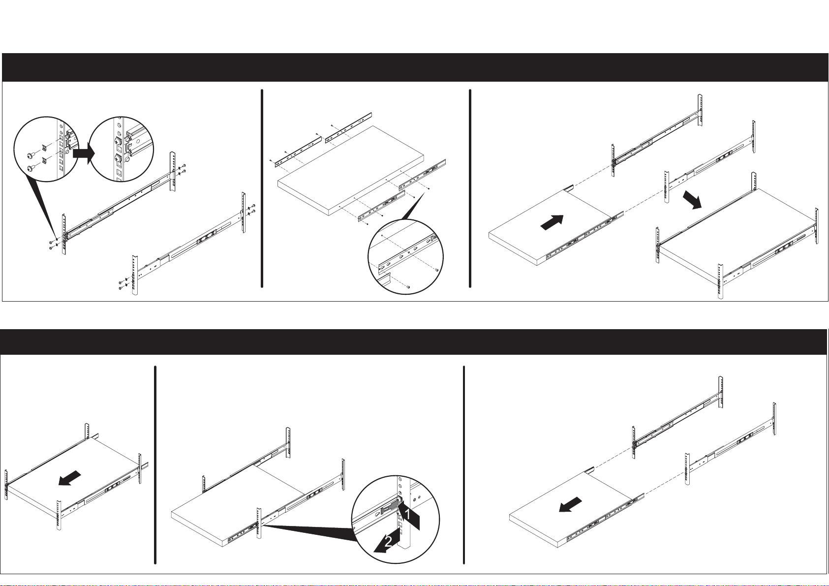
Installation
3C02-610
Removal
PressPress
1. Install the rails to the rack. 2. Screw the longer inner rail on
thechassisbyM4screw.
3. Install the chassis.
1. Under close condition. 2. Pull out the chassis half way to the lock
position and press release stop from both
sides accordingly to fully pull out the chassis.
Table of contents


