N/A
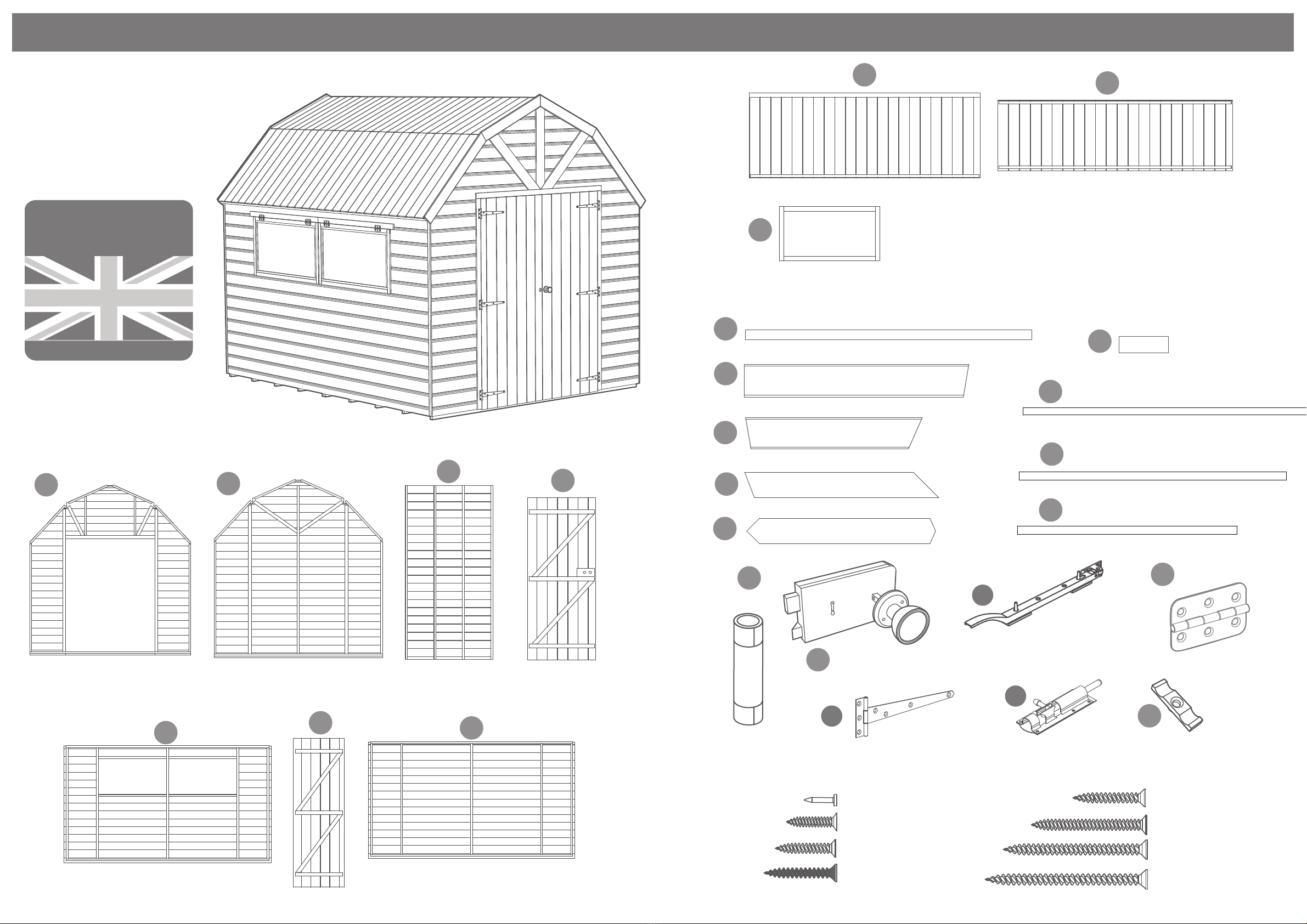
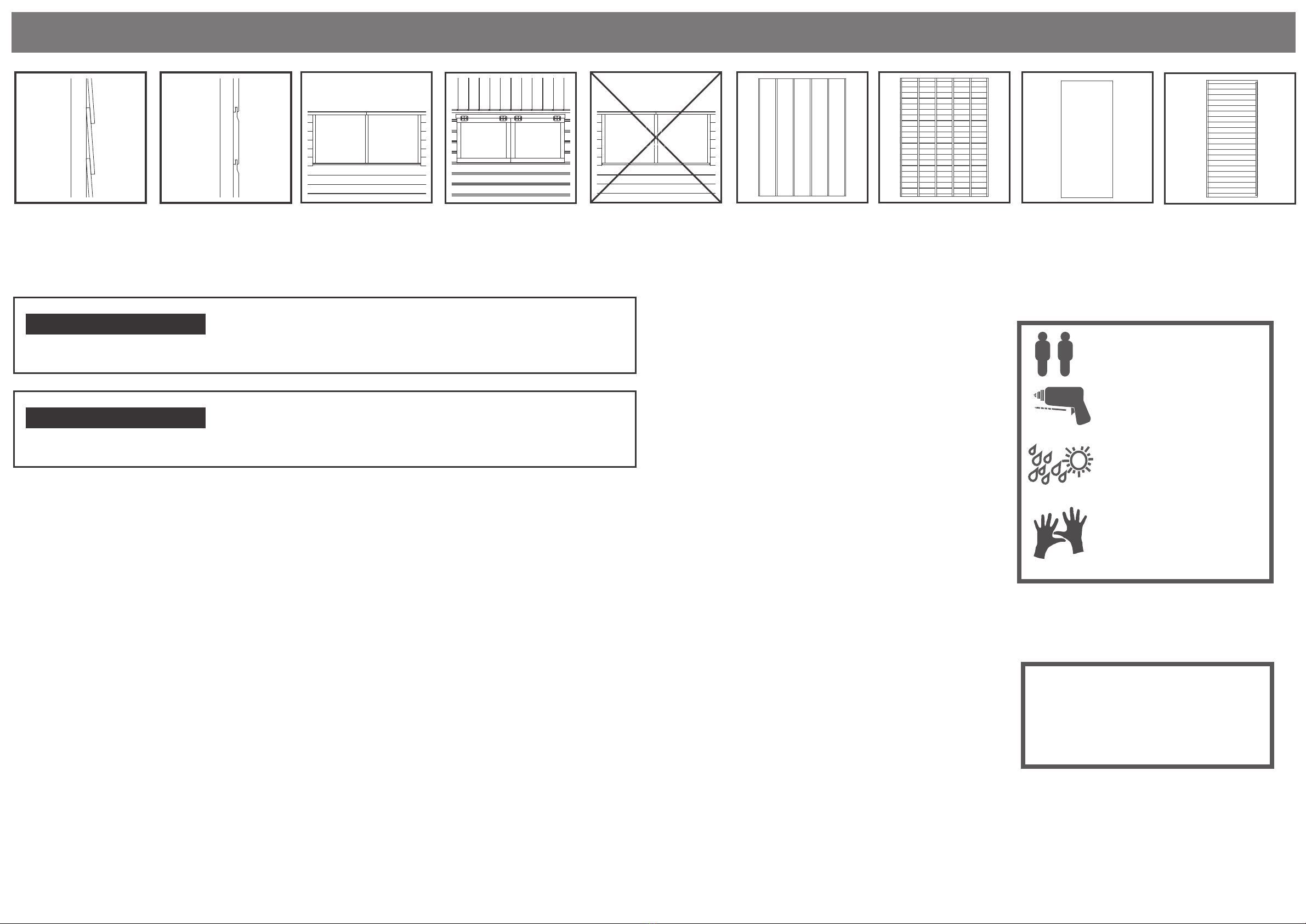
Overlap
Cladding
Shiplap
Cladding
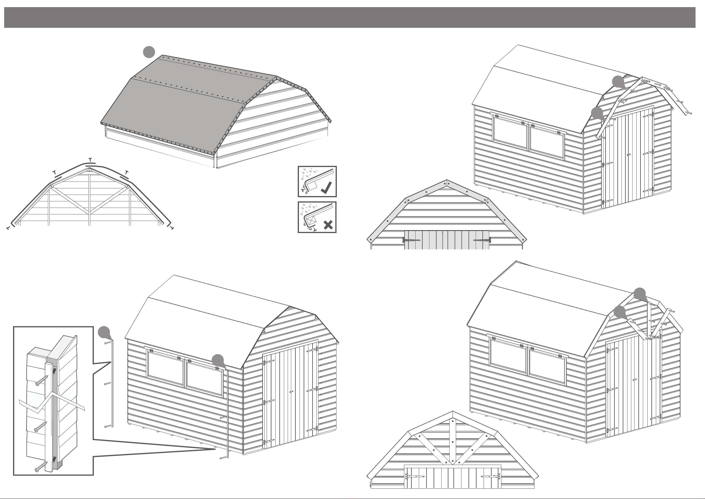
Solid Sheet
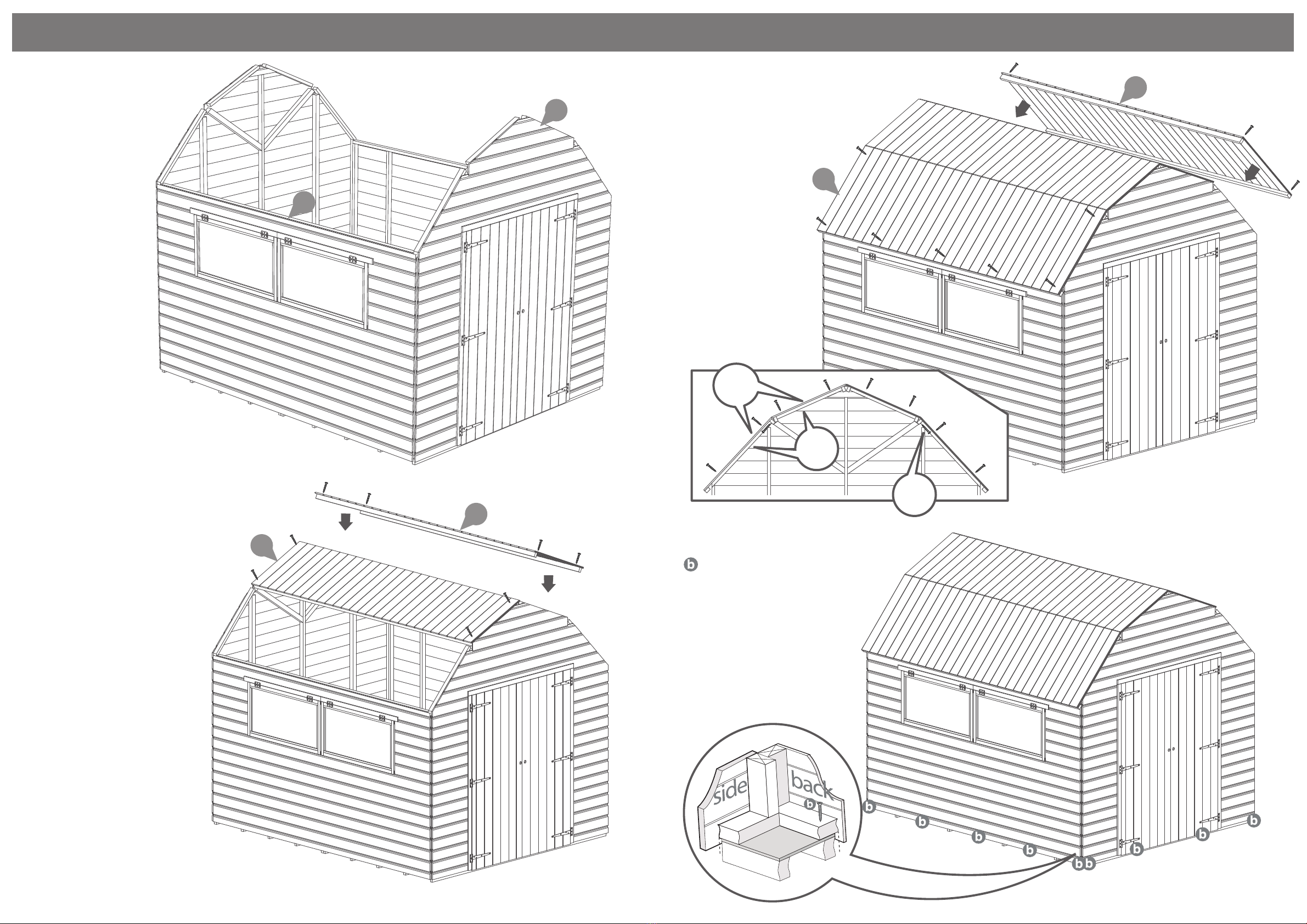
Roof
T&G Roof
Solid Sheet
Floor
T&G Floor
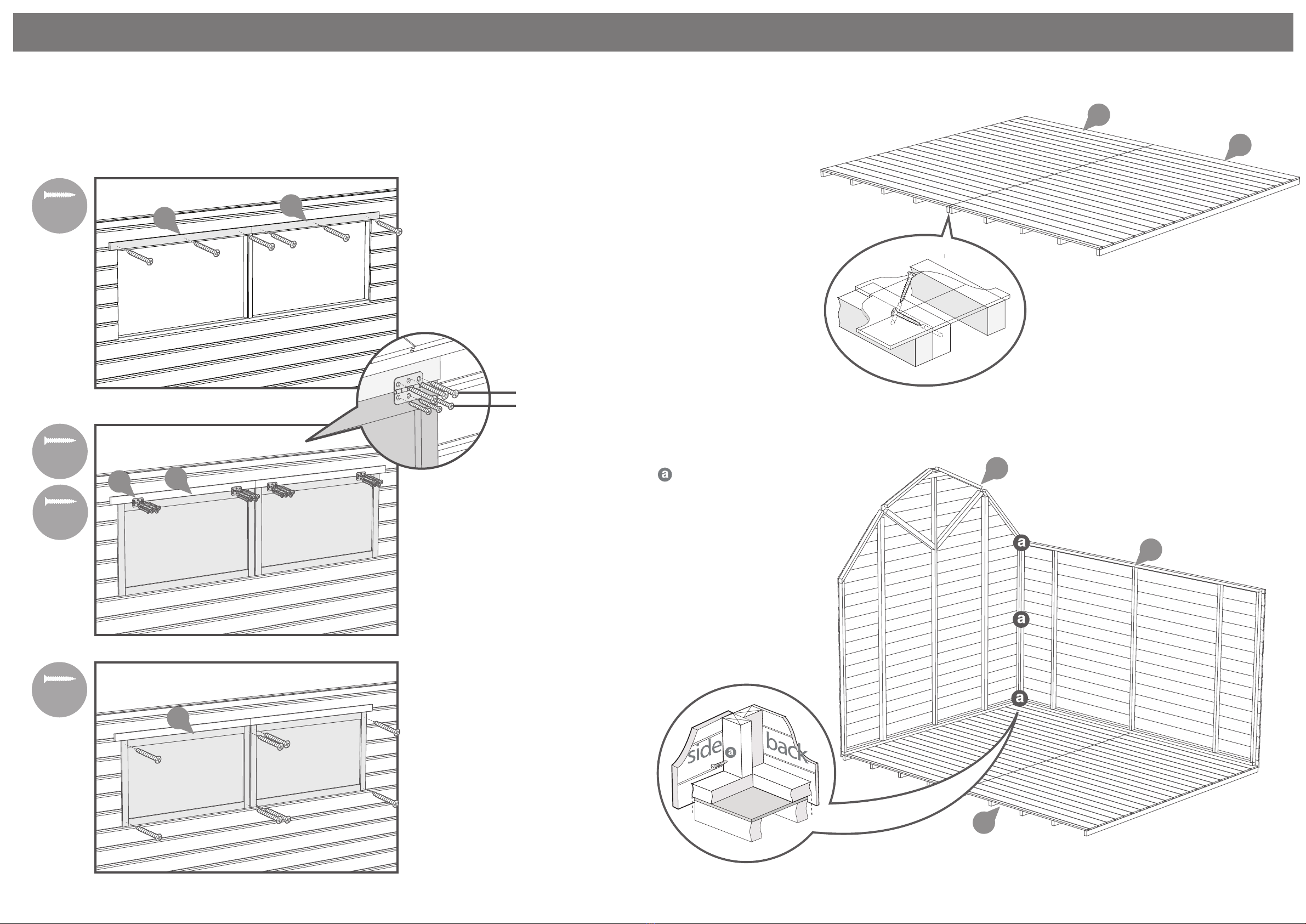
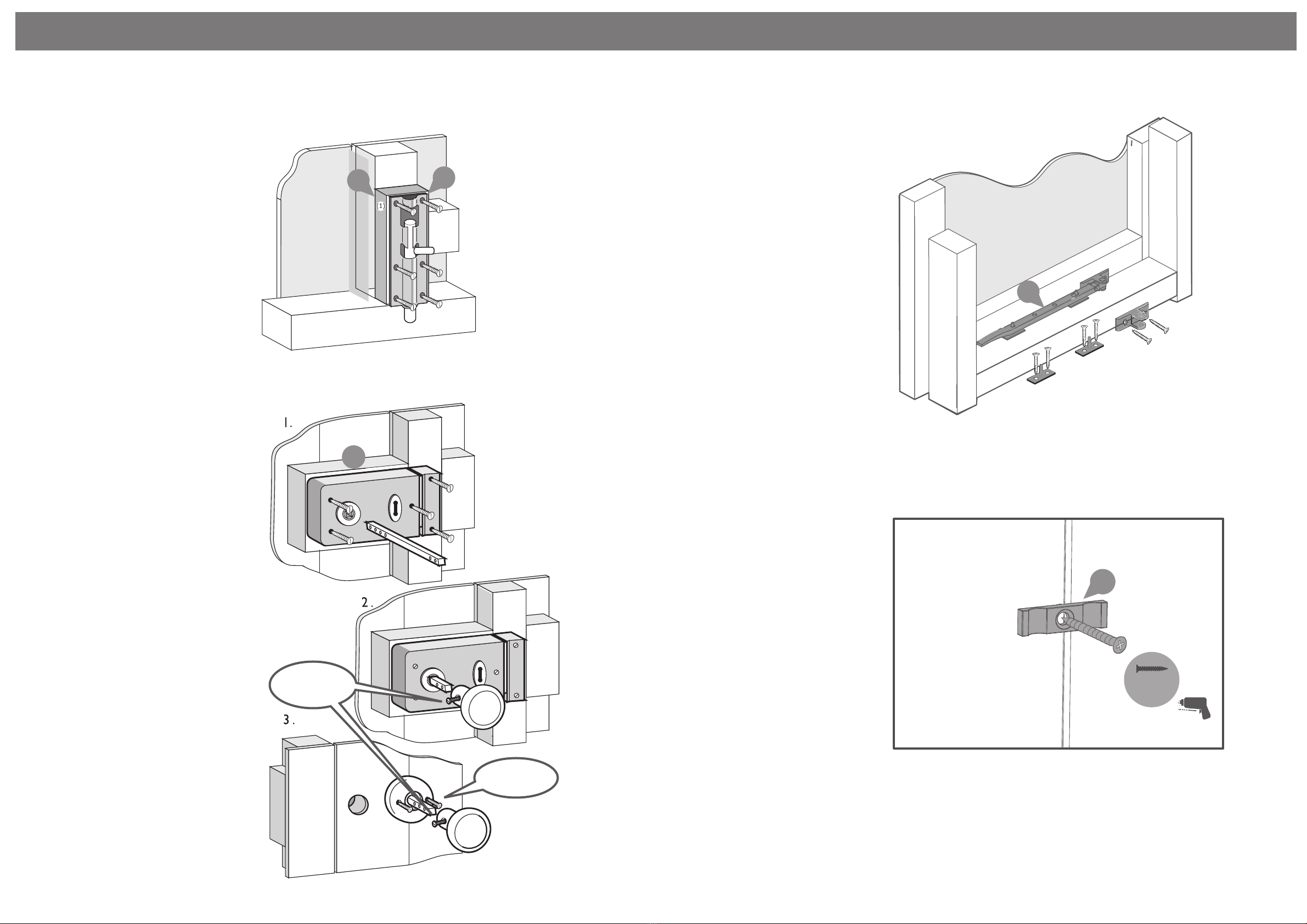
Fixed
Windows
Opening
Windows
No
Windows
For Assistance Please
Contact Customer Care on
01636 880514
2mm Drill bit
x2
Winter = High Moisture = Expansion
Summer = Low Moisture = Contraction
All building’s should be erected by two
adults
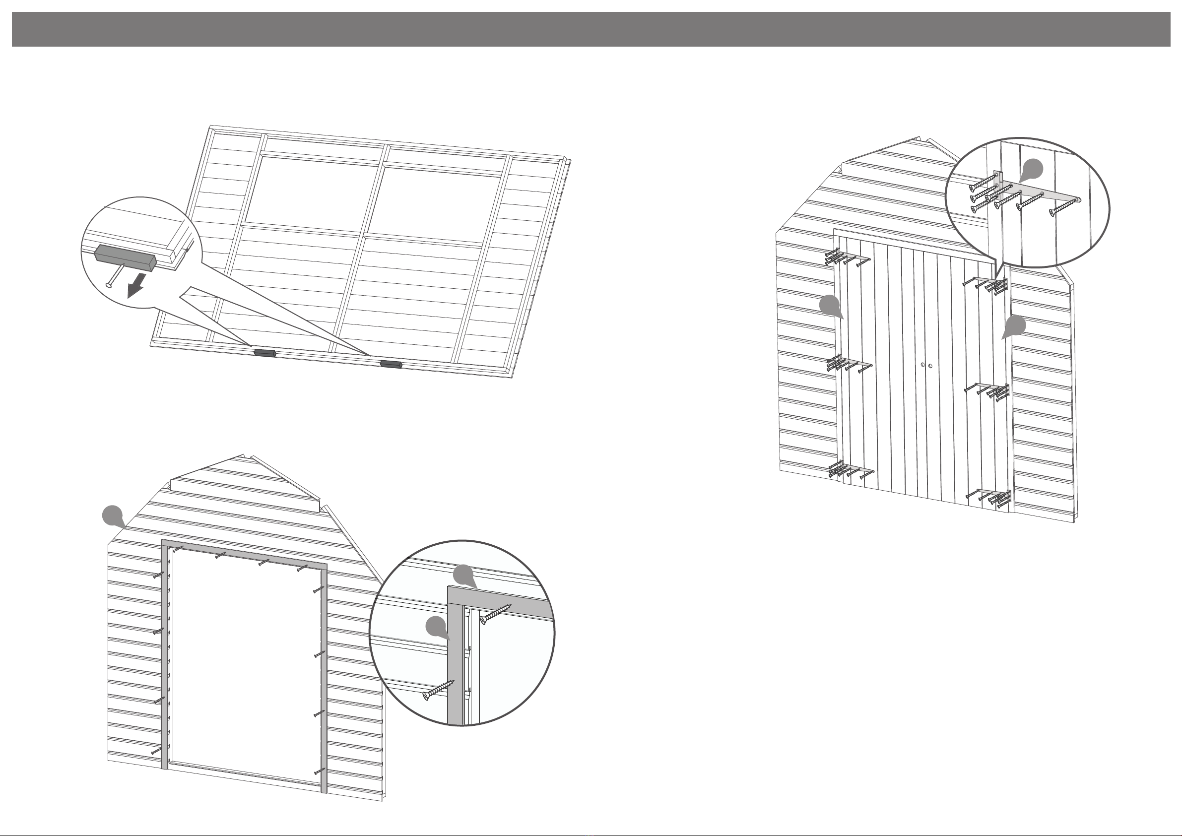
For ease of assembly, it is advisable to
pilot drill all screw holes and ensure
all screw heads are countersunk.
BEFORE YOU START PLEASE READ INSTRUCTIONS CAREFULLY
- Check the pack and make sure you have all the parts listed.
- When you are ready to start, make sure you have the right tools at hand
(not supplied) including a Phillips screwdriver, Stanley knife, wood saw,
step ladder and drill with 2mm bit.
- Ensure there is plenty of space and a clean dry area for assembly.
TIMBER
As with all natural materials, timber can be aected during various weather
conditions. For the duration of heavy or extended periods of rain, swelling of the
wood panels may occur. Warping of the wood may also occur during excessive
dry spells due to an interior moisture loss. Unfortunately, these processes cannot
be avoided but can be helped. It is suggested that the outdoor building is
sprayed with water during extended periods of warm sunshine and sheltered as
much as possible during rain or snow.
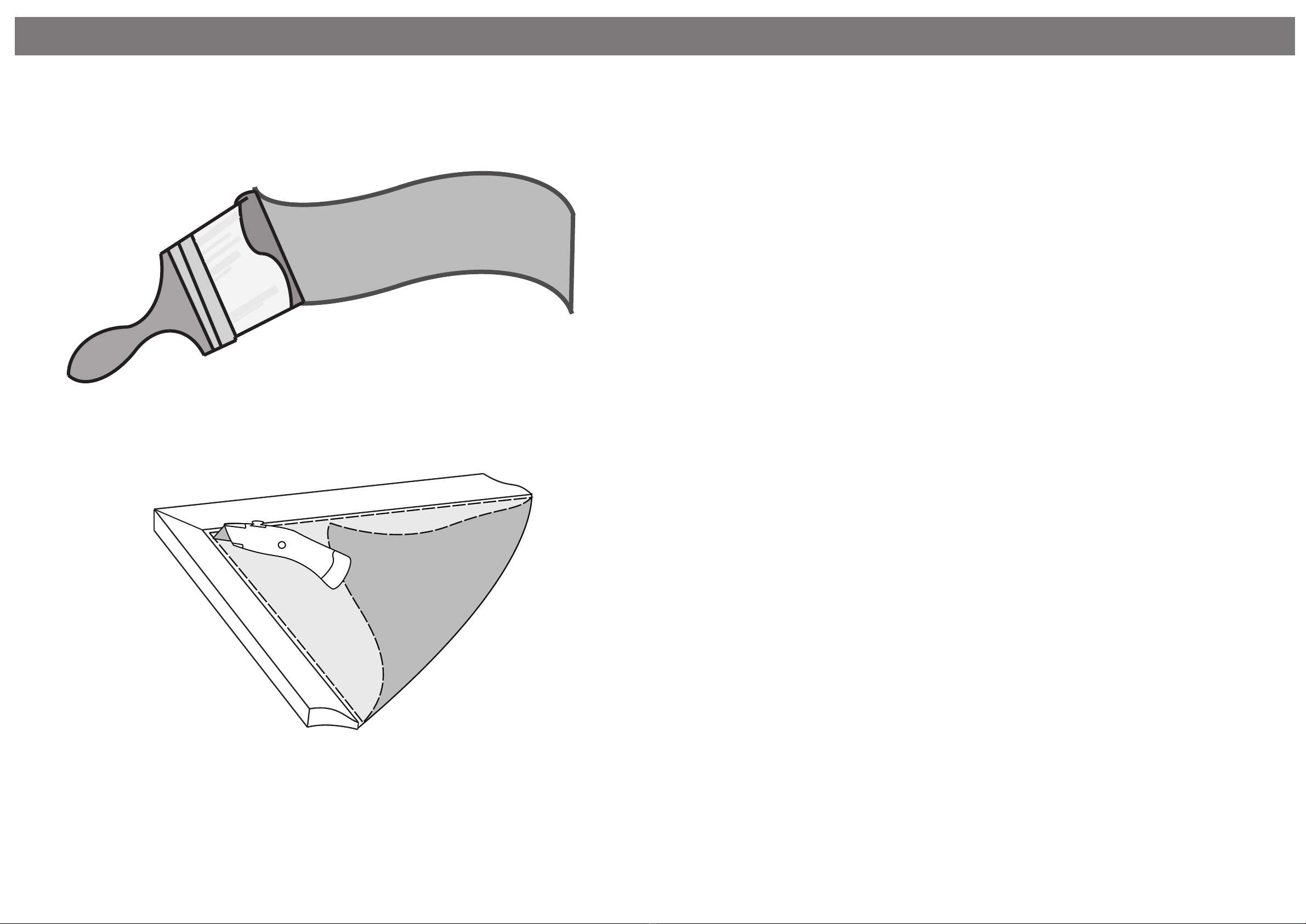
Our buildings are coated with a water based high quality colorant**; this only
helps to
protect the product during transit and for up to 3 months against mould. To
validate your guarantee and ensure longevity of the product, it is ESSENTIAL the
building is treated with a wood preserver within the rst three months of
assembly and thereafter in accordance with the manufactures recommenda-
tions.
Care must be taken to ensure the product is placed on a suitable base
BUILDING A BASE
When thinking about where the building and base is going to be constructed:
Ensure that there will be access to all sides for maintenance work and annual
treatment.
Whilst all products manufactured are made to the highest standards of Safety and in the case of childrens products
independently tested to EN71 level, we cannot accept responsibility for your safety whilst erecting or using this product.
Mercia Garden Products Limited, Sutton On Trent, Newark, Nottinghamshire, NG23 6QN
www.merciagardenproducts.co.uk
CAUTION
Every eort has been made during the
manufacturing process to eliminate the
prospect of splinters on rough surfaces
of the timber. You are strongly advised
to wear gloves when working with or
handling rough sawn timer.
Ensure the base is level and is built on rm ground, to prevent distortion. Refer
to diagrams for the base dimensions, The base should be slightly smaller than
the external measurement of the building, i.e. The cladding should overlap the
base, creating a run o for water. It is also recommended that the oor be at
least 25mm above the surrounding ground level to avoid ooding.
TYPES OF BASE
- Concrete 75mm laid on top of 75mm hard-core.
- Slabs laid on 50mm of sharp sand.
Please retain product label and instructions for future reference
P 1
General Instructions
01GRODB0808-V1
8x8 Dutch Barn Style Shed with Double Doors, Opening Window and T&G Floor and Roof.
01GRODB1008-V1
10x8 Dutch Barn Style Shed with Double Doors, Opening Window and T&G Floor and Roof.
Refer to the instructions pages for you specic product code