For Assistance Please
Contact Customer Care on
01636 880514
2mm Drill bit
x2
Winter = High Moisture = Expansion
Summer = Low Moisture = Contraction
All building’s should be erected by two
adults
For ease of assembly, it is advisable to
pilot drill all screw holes and ensure
all screw heads are countersunk.
BEFORE YOU START PLEASE READ INSTRUCTIONS CAREFULLY
- Check the pack and make sure you have all the parts listed.
- When you are ready to start, make sure you have the right tools at hand
(not supplied) including a Phillips screwdriver, Stanley knife, wood saw,
step ladder and drill with 2mm bit.
- Ensure there is plenty of space and a clean dry area for assembly.
TIMBER
As with all natural materials, timber can be aected during various weather
conditions. For the duration of heavy or extended periods of rain, swelling of the
wood panels may occur. Warping of the wood may also occur during excessive
dry spells due to an interior moisture loss. Unfortunately, these processes cannot
be avoided but can be helped. It is suggested that the outdoor building is
sprayed with water during extended periods of warm sunshine and sheltered as
much as possible during rain or snow.
Our buildings are pre treated with a water based treatment**; this only helps to
protect the product during transit and for upto 3 months against mould. To
validate your guarantee and ensure longevity of the product, it is ESSENTIAL the
building is treated with a wood preserver within the rst three months of
assembly and thereafter in accordance with the manufactures recommenda-
tions. Care must be taken to ensure the product is placed on a suitable base.
BUILDING A BASE
When thinking about where the building and base is going to be constructed:
Ensure that there will be access to all sides for maintenance work and annual
treatment.
Whilst all products manufactured are made to the
highest standards of Safety and in the case of childrens
products independently tested to EN71 level,we cannot
accept responsibility for your safety whilst erecting or
using this product.
Mercia Garden Products Limited, Sutton On Trent, Newark, Nottinghamshire, NG23 6QN
www.merciagardenproducts.co.uk
CAUTION
Every eort has been made during the
manufacturing process to eliminate the
prospect of splinters on rough surfaces
of the timber. You are strongly advised
to wear gloves when working with or
handling rough sawn timer.
**Protim Fentex E5**
Biocidal Product Regulation (EU 528/2012) Article 58 Information
Protim Fentex E2 preserved wood is a“treated article” which incorporates biocidal products.
Wood correctly preserved with Protim Fentex E2 is protected against mould in storage.
Contains: IPBC (3-iodo-2-propynyl-N-butyl carbamate) and propiconazole.
Wear gloves when handling freshly treated wood.
Avoid breathing dust when cutting treated or untreated wood.
Dispose of o-cuts responsibly – do not burn.
Ensure the base is level and is built on rm ground, to prevent distortion. Refer
to diagrams for the base dimensions, The base should be slightly smaller than
the external measurement of the building, i.e. The cladding should overlap the
base, creating a run o for water. It is also recommended that the oor be at
least 25mm above the surrounding ground level to avoid ooding.
TYPES OF BASE
- Concrete 75mm laid on top of 75mm hard-core.
- Slabs laid on 50mm of sharp sand.
P 1
02SNO0705-V2 Contents
Overall Dimensions:
Length = 1819mm
Width = 2310mm
Height = 2020mm
Base Dimensions:
Length = 1448mm
Width = 2082mm
Please retain product label and instructions for future reference
Before assembly
please make sure you have a
suitable base ready to erect your
building
MADE IN GREAT BRITAIN
Door Gable Plain Gable
Plain Side
Floor
1st floor
Rail Guard
Large Roof Sheet
1795 x 1400mm
Small Roof Sheet
1795x990mm
12
3
456
78
9
Window Side
Door
10
Fixing Kit
Support Block - 495mm x3
20
11
12
13
14
15
16
17 18
19
Roof Eave - 1795mm x2
Roof Support Bar - 1448mm x1
Fascia - 1427mm x2
Ladder Sides - 1418mm x2
1st Floor Support Bar - 1270mm x 1
Fascia - 1041mm x2
Ladder Step - 390mm x4
Fascia Block
140mm x1
Finial x2
21 22
23
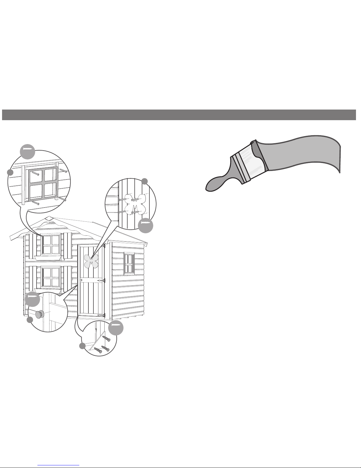
Door Stop x1
Window Frame x3
Butterfly x1
Window Shutters x4
Window Box x2 25
24