Merck EMD Millipore NovAseptic User manual

Installation and User
Guide
NovAseptic®GMP ATEX Mixer
NovAseptic and the Vibrant M are trademarks of Merck KGaA, Darmstadt, Germany or its aliates. All other trademarks are the
property of their respective owners. Detailed information on trademarks is available via publicly accessible resources. © 2008-
2018 Merck KGaA, Darmstadt, Germany and/or its aliates. All Rights Reserved.
00105442PU Rev 5 02/2018

2 Installation and User Guide

Contents
Installation Note ......................................................................................... 5
Operator and Equipment Safety .................................................................... 6
Labeling .................................................................................................... 7
NovAseptic®GMP ATEX Mixer Components ..................................................... 8
Mixing Head (AX#/12#) ........................................................................ 8
Male Bearing (AX#/24#) ....................................................................... 8
Tank Plate (AX#/33) ............................................................................ 8
Drive Unit (AX#/41-E#) ........................................................................ 8
Required Tools ..................................................................................... 9
Optional Equipment .............................................................................. 9
Installation and
Operating Parameters ................................................................................. 9
Noise Level and Vibrations ..................................................................... 9
Installation .............................................................................................. 10
Male Bearing Installation ..................................................................... 10
Mixing Head Installation ...................................................................... 11
Drive Unit Installation ......................................................................... 11
Electrical Installation .......................................................................... 13
Operation ................................................................................................ 15
Starting the Mixer .............................................................................. 15
Operating Notes ................................................................................. 16
Disassembly ...................................................................................... 16
Storage ............................................................................................. 16
Recycle and Disposal .......................................................................... 16
Cleaning and Sterilizing Procedures ............................................................. 17
Cleaning in Place (CIP) ........................................................................ 17
Sterilizing in Place (SIP) ...................................................................... 17
Installation ATEX Checklist ......................................................................... 19
Install the Male Bearing ...................................................................... 19
Install the Mixing Head ....................................................................... 19
Before Installing the Drive Unit ............................................................ 19
Install the Drive Unit – GMP 50 ATEX, GMP 100 ATEX, GMP 500 ATEX ........ 19
Install the Drive Unit – GMP 1000 ATEX and GMP 2000 ATEX .................... 20
Install the Drive Unit – GMP 5000 ATEX, GMP 10000 ATEX,
GMP 20000 ATEX ................................................................................ 20
Before Installing the Electrical Components ............................................ 20
Install the AC Motor ............................................................................ 20
Install the Revolution Counter .............................................................. 20
Install the VFD System ........................................................................ 21
Commissioning ......................................................................................... 22
Valid Regulations ................................................................................ 22
Installation Qualication Checklist ............................................................... 23
Installation Qualication ..................................................................... 23
Maintenance Checklist ............................................................................... 25
Spare Parts .............................................................................................. 27
Troubleshooting ........................................................................................ 28
Standard Warranty ................................................................................... 30
NovAseptic® GMP ATEX Mixer 3

4 Installation and User Guide

Installation Note
The ATEX mixer is designed for operation in the classification noted on the product label.
The mixer must be in good working order before operating.
Before using the mixer, ensure the following:
• The tank plate is installed properly on the tank and concentricity and alignment have been
verified to prevent any contact between the mixing head, outer rotor and tank plate. If the
tank plate is warped during welding or not aligned properly with the tank surface, remove and
discard it and replace it with a new tank plate. The tank plate cannot be repaired if damaged.
• Verify that the mixer drive unit is in proper working order prior to attaching to the tank plate.
If the drive unit has been dropped, check for damage. After installation, verify that the mixer
drive is properly mounted to the tank plate. If there is any damage to the drive unit, ensure it is
repaired before using.
• If, when dropped, the outer magnet was damaged or the outer magnet drive shaft is bent,
attach the drive unit to the tank plate and manually check to determine if there is any contact
between the outer magnet and tank plate. If there is any contact, do not operate the mixer and
have it repaired prior to use.
NovAseptic® GMP ATEX Mixer 5
Operator and Equipment Safety
All installers and operators of the equipment must read and understand this
installation and user manual before using this equipment. Failure to follow operating
and installation instructions could result in operator injury or damage to the
equipment.
Any attempt to use the NovAseptic® GMP ATEX Mixer equipment in a manner not
specified in this manual may result in damage to the equipment, voiding of product
warranty, and possible operator injury.
Any of the following can damage the mixer: external load, reaction forces, torque,
corrosion, erosion, fatigue and the decomposition of unstable liquids.
Prior to operation, the equipment must be fully assembled according to the
instructions in this manual.
Use appropriate personal protective equipment and eye protection when operating the
equipment.
Protect drive unit against dust.
The drive unit may be heavy. Use appropriate equipment to avoid injury.
Do not install components close to rotating parts of the GMP ATEX Mixer.
During mixing operations, mixer parts may become hot to the touch.
Do not insert fingers into equipment; pinching may occur.
Do not run with an empty vessel.
Check that all components in the mixer are of correct size.
Handle the mixing head and male bearing with care; bearing material is hard and
brittle.
The mixing head must always be completely submerged.
System must be properly grounded.
To eliminate any risk of electrostatic charges in ATEX IIC environments, clean the
surface of the Drive Unit using only a damp cloth.
Tachometer must be connected to an intrinsically safe barrier.
The mixer must be operated with a variable frequency drive.
Check the magnetic parts of the GMP ATEX Mixer regularly for foreign materials.
Ensure that the process fluid does not contain magnetic particles.
Keep electrically controlled medical devices and magnetically stored media away from
magnetic parts of the GMP ATEX mixer.
Follow Ex regulations applicable to the GMP ATEX mixer.
6 Installation and User Guide

Labeling
Part No: AX20/33
GMP2000 Tank Plate 316L/1.4435, ATEX
JAD00388ID No:
Millipore SAS, 67120 Dachstein, France
www.millipore.com
NovAseptic Mixer
2009/26Production year/week :
DNV-2003-OSL-ATEX-0227X
0081 II 1/2 GD c T4
Figure 1: Product label
Number Description
10081 – LCIE. Notified body identification number.
2II – The mixer is classified for explosion group IIC.
3
1/2 – Category 1/2. The mixer parts inside the vessel can be used in
zone 0, 1, 2, 20, 21, 22 and the outside parts in zone 1, 2, 21, 22:
Category Zone Explanation
10 (gases) Flammable material present continuously or for long periods.
20 (dusts)
21 (gases) Flammable material present occasionally in normal operation.
21 (dusts)
32 (gases) Flammable material present in abnormal conditions for short
periods.
22 (dusts)
4
GD – Category GD is intended for use in hazardous areas, in which explosive gases
and dust are present.
G – Category G is intended for use in hazardous areas, in which explosive gases are
present.
D – Category D is intended for use in hazardous areas, in which explosive dust are
present.
5
c – Constructual safety. A type of ignition protection in which constructional measures
are applied so as to protect against the possibility of ignition from hot surfaces, sparks
and adiabatic compression generated by moving parts. For further information read EN
13463-5.
6
T4 – Maximum Design temperature: T4 (135 °C) [275 °F]. The mixer can be used in
temperatures T1-T4.
0 °C (32 °F) ≤ Ta ≤ +40 °C (104 °F ) The ambient temperature must not exceed 40 °C
(104 °F).
®
1
2
3456
NovAseptic®GMP ATEX Mixer 7
NovAseptic®GMP ATEX
Mixer Components
Catalog numbers and specifications for the
components listed here can be found on the
appropriate specification sheet.
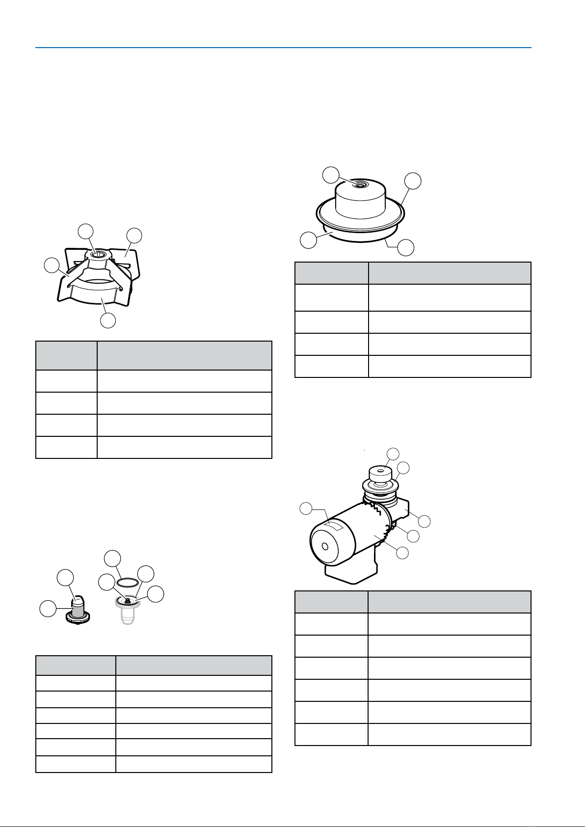
Mixing Head (AX#/12#)
Handle the mixing head with care. The bearing
material is hard and brittle. Keep the magnetic body
away from any particles that may adhere to it.
xxxxxxx
3
4
2
1
Key
Number Description
1 Magnetic body
2 Wings
3 Silicone carbide female bearing
4 Serial number
Male Bearing (AX#/24#)
The male bearing keeps the mixing head in a
correct position; it mounts on the tank plate
inside vessel.
x
x
x
x
x
x
x
5
9
6
8
10
7
Key Number Description
5 Stainless steel support
6Silicone carbide bearing
7 Connection thread
8Groove
9O-ring
10 Serial number
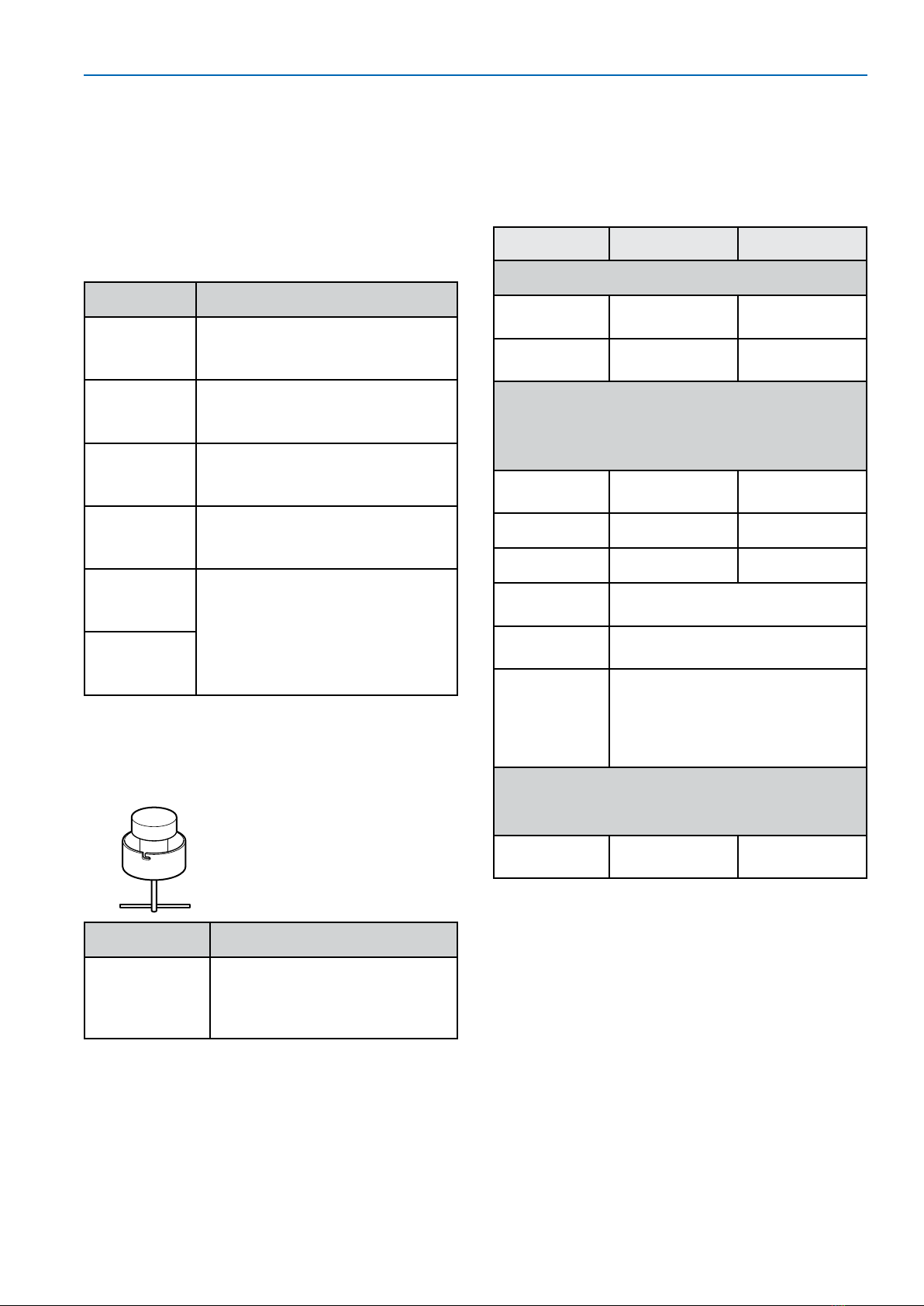
Tank Plate (AX#/33)
Each tank plate is marked with the serial
number and a mill stamp that corresponds to
its heat number. The tank plate is welded onto
the vessel and is considered an integrated part
of the vessel. The tank plate must comply with
your local pressure vessel code.
11 12
14
13
Welded tank plate
Key Number Description
11 Male bearing connection
thread
12 Welding edge
13 Drive unit connection flange
14 Serial number
Drive Unit (AX#/41-E#)
The drive unit delivers the rotating torque to
the mixing head and is mounted on the outside
of the vessel.
21
16
17
18
19
20
x
x
x
x
x
x
Key Number Description
16 Magnetic outer drive head
17 Tank plate connection flange
18 Gearbox unit
19 Revolution counter
20 Motor
21 Serial number label
8 Installation and User Guide
Required Tools
The following tools are required for installation
of the NovAseptic® GMP ATEX Mixer. The
tools (shown below) are not included with
the mixer and are available from your local
representative. Component catalog numbers
and specifications can be found on our web
site.
Description Purpose
NovAseptic®
Gauges 1
and 2
Checks the tank plate
deformation.
Multi tool
(GT#/25)
Installation tool for mixing
head and male bearing for use
in small vessels.
Tightening
tool
(GT#/26)
Installation tool for male
bearing.
Heatsink
tank plate
(G94-#)
Attached to the tank plate
during welding to prevent
deformation.
NovAseptic®
gauge 1
(G91-#) For verification of geometry
after welding.
NovAseptic®
gauge 2
(G92-#)
Optional Equipment
Catalog numbers and specifications for the
component shown here can be found at www.
millipore.com.
Description Purpose
Mixing head
attractor
(GT#/AW)
Keeps the mixing head in
place when vessel is moved.
Replaces the drive unit during
transport.
Installation and
Operating Parameters
Please refer to the appropriate product
specification sheet for more information.
Parameter Minimum Maximum
Tank Plate
Temperature -80 °C
(-112 °F)
200 °C
(392 °F)
Pressure -1 barg
(-14.5 psig)
10 barg
(145 psig)
Mixing Head, Male Bearing, and Tank
Plate
Defines the operating parameters inside the
vessel
Temperature 5 °C (41 °F) 135 °C
(275 °F)
pH 1 14
Viscosity 1 cP 800 cP
Media Media may not contain
magnetic particles.
Rotation
speed
See Product Specification
Sheet.
Minimum
acceleration
and
deacceleration
time
Five seconds (specific to each
application; set accordingly).
Drive Unit
Defines the operating parameters outside the
vessel
Ambient
temperature 0 °C (32 °F) 40 °C (104 °F)
Noise Level and Vibrations
Motor noise levels are measured according to
ISO®1680 standard, and are within maximum
levels specified by standards IEC 60034-9.
Vibration falls under standard class N, as
specified by standard IEC 60034-14.
The noise level and vibration of the motor
installed in the tank must be evaluated before
the complete installation is declared compliant
with appropriate equipment directives.
NovAseptic®GMP ATEX Mixer 9
Installation
Use the Installation Checklist and the
Installation Qualification Checklist (in this
manual) as guides for installing the mixer and
initiating use. Use the Maintenance Checklist
as a guide for follow up care of the mixer.
For welding of the Tank Plate use GMP ATEX
Welding Instructions.
Install the GMP ATEX Mixer components in the
following order:
4
x
x
x
x
x
x
5
2
1
3
1. Tank plate
2. Male bearing
3. Mixing head
4. Drive unit
5. Revolution counter
Male Bearing Installation
See NovAseptic® Mixer Male Bearing
Installation Guide 00101868PU for additional
information.
• The vessel must be clean and completely
dry inside.
• Do not use grip tools on bearing surfaces.
• Follow all local safety codes before entering
the vessel.
• Handle the male bearing with care.
Mounting the Male Bearing
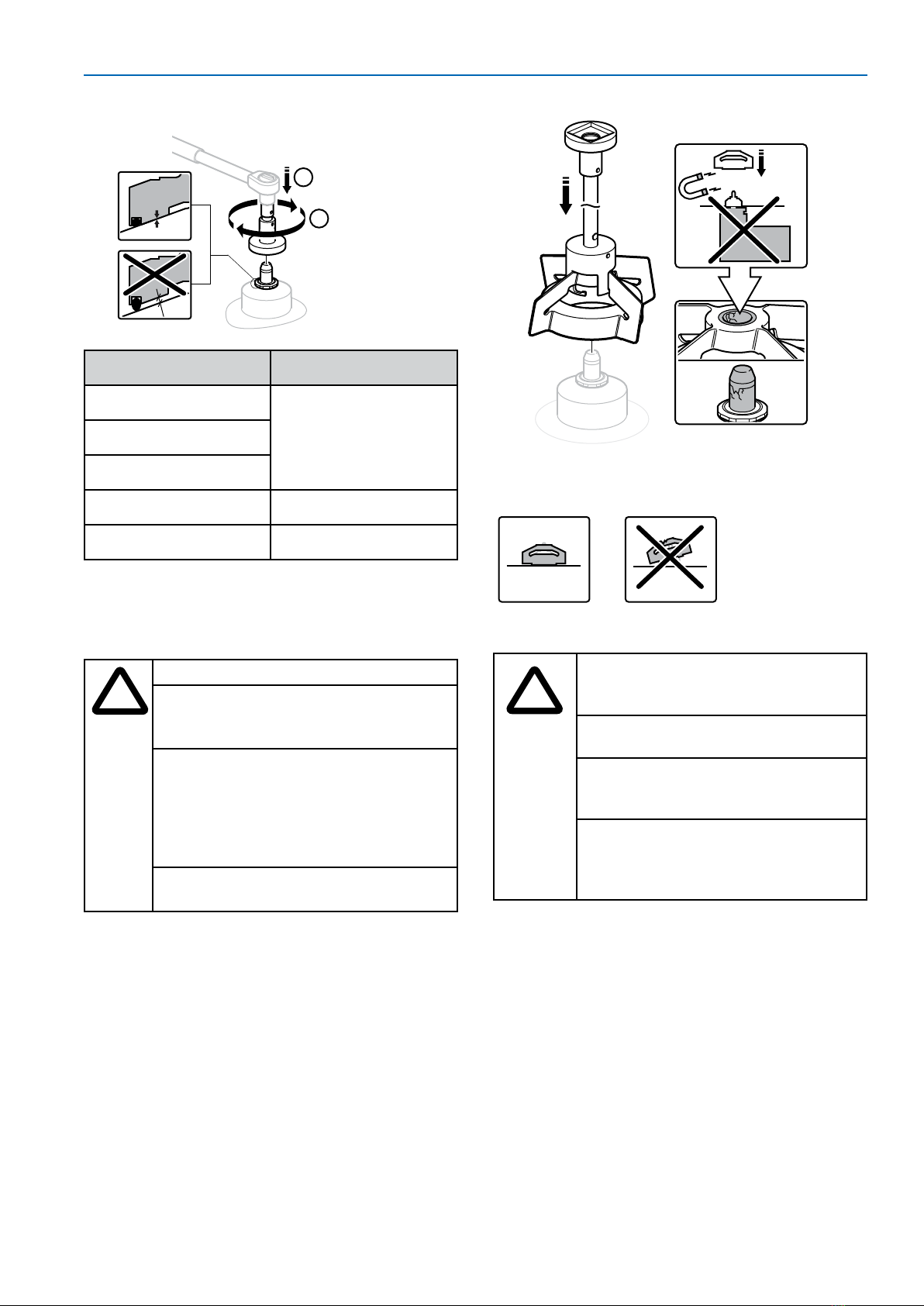
1. Ensure proper position of the O-ring on the
male bearing.
2. For minimal friction, lubricate the visible
part of the O-ring with a small amount of
purified water.
H2O
360°
3. Remove the protective cap. Ensure that the thread
connection in the tank plate and male bearing are
clean, dry, and free from foreign material.
1
2
4. Tighten the male bearing clockwise by hand
into the thread of the tank plate, making
sure that it is aligned with the center line of
the tank plate.
1
2
5. Position the male bearing in the appropriate
tightening tool or multi-tool with a torque
wrench. Ensure that the tool fits the nut.
Tighten the bearing to metal-to-metal
contact by applying recommended torque
according to table below.
Important: Ensure metal-to-metal contact
by applying recommended torque in table
below. If bearing is not installed properly it
may come off.
10 Installation and User Guide
3
4
Catalog Number Torque
AX05/24#
6 Nm (4.4 Lbft)AX1/24#
AX510/24#
AX20/24# 13 Nm (9.6 Lbft)
AX50200/24# 30 Nm (22.1 Lbft)
Mixing Head Installation
See NovAseptic® GMP Mixing Head Installation
Guide 00101868PU for additional information.
!
Handle the mixing head with care.
Use extreme care when mounting
the mixing head on to the male
bearing; mixer bearings are brittle.
Do not mount the drive unit before
installing the mixing head. The
powerful magnetic force between
the mixing head and the outer drive
head may cause severe damage to
bearings as well as personal injury.
Follow all local safety codes before
entering the vessel.
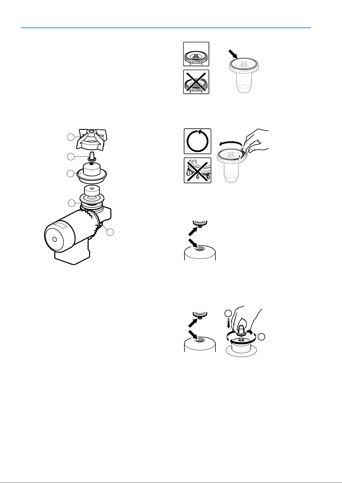
1. Remove any foreign magnetic particles
from the mixing head.
If the mixing head must be placed on a
table, place the female bearing downward
to prevent magnetic particles from
adhering to the magnetic surface of the
mixing head.
2. Remove the drive unit.
3. Install the mixing head using the multi-tool.
Mixing head sizes GMP 5 000–20 000ATEX
must be installed by hand.
4. Carefully position the mixing head by
turning it while lowering it onto the male
bearing.
Align the mixing head with the tank plate.
Ensure that the mixing head rotates smoothly.
Drive Unit Installation
!
The drive unit may be heavy. Use
appropriate equipment to avoid
injury.
Never use the drive unit without a
frequency converter.
See the Electrical Installation
section of this user guide for
electrical information.
To eliminate any risk of electrostatic
charges in ATEX IIC environments,
clean the surface of the Drive Unit
using only a damp cloth.
Before installation
• Ensure that all incoming power is equipped
with an emergency stop and an on/off
switch that can be locked in both positions.
• Ensure that the motor cables are shielded
(to avoid disturbance).
• Ensure that the drive unit is properly
grounded.
• Ensure that the electric cables are long
enough so that the drive unit can be
disassembled and removed from the vessel.
• The mixing head must be covered with
liquid before starting the unit.
NovAseptic® GMP ATEX Mixer 11
• Store the motor in an area which is humid
and weather proof. Ensure that motor is
on a stable surface to prevent falling or
vibration.
• Remove the transport collar before
installing the motor.
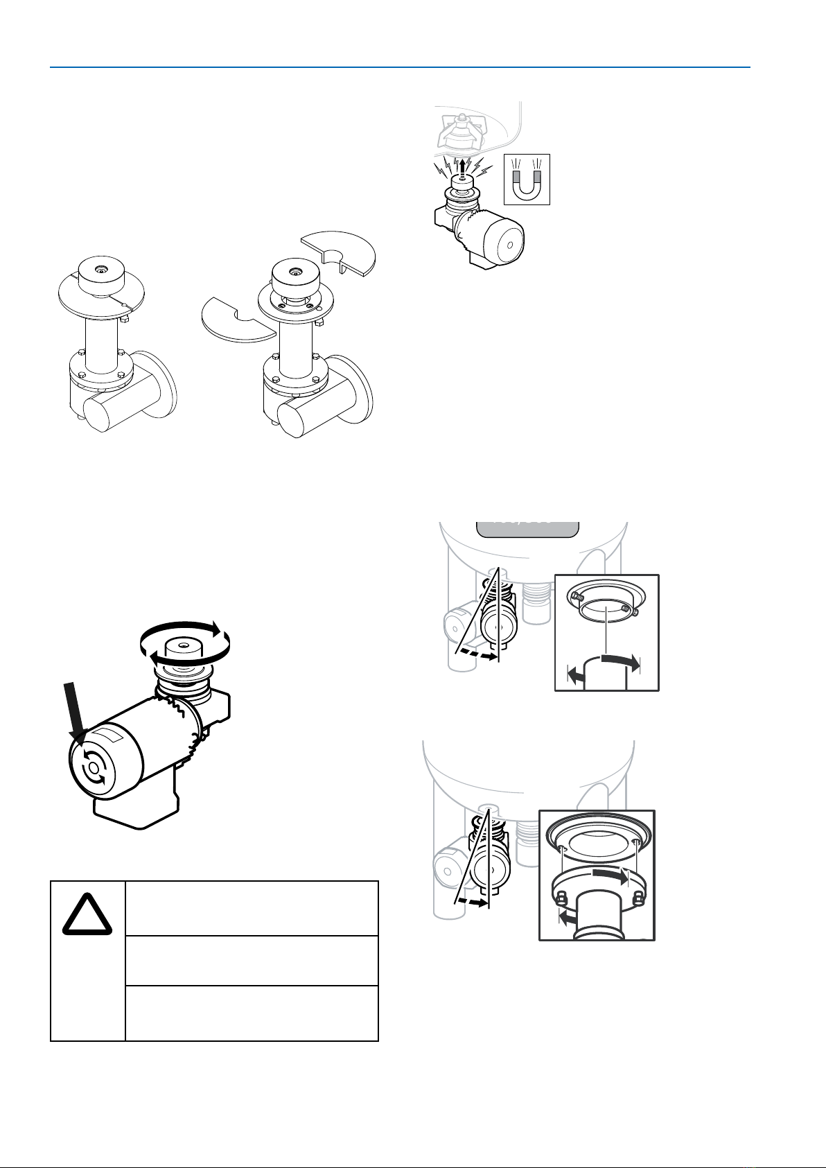
Check Direction of Rotation
Turn on the motor. Verify that the outer drive
head rotates clockwise and the fan rotates
counterclockwise.
A sticker on the motor indicates the correct
rotation direction of the fan.
Mounting the Drive Unit
!
Handle the drive unit with caution
to avoid personal injury and
damage to the equipment.
Do not make any adjustments to
screws and bolts.
There is a powerful magnetic
force between the mixing head
and the outer drive head.
Mount the drive unit onto the vessel following
the instructions for the appropriate mixer size:
GMP 50 ATEX, GMP 100 ATEX and GMP
500 ATEX
1. Install the drive unit into the tank plate.
Put the two studs on the tank plate into the
slots on the drive unit.
2. Turn the drive unit clockwise (view from
below) to the stop position, approximately
15º.
3. Tighten the two nuts with a wrench.
15°
GMP 50,
100, 500
GMP 1000 ATEX and GMP 2000 ATEX
10°
1. Tighten the screws (1) clockwise (view
from below).
12 Installation and User Guide
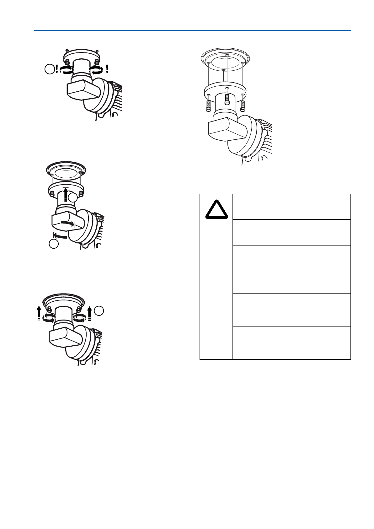
1
2. Install the drive unit onto the tank plate.
Insert the locking screws into the two oval
holes in the tank plate (2).
310°
2
3. Turn the drive unit clockwise (3) (shown
from below) to the stop position,
approximately 10º .
4
4. Tighten the two screws counterclockwise
(4) (shown from below) with a wrench.
GMP 5000 ATEX, GMP 10000 ATEX and
GMP 20000 ATEX
1. Install the drive unit onto the tank plate.
Align the four holes in the drive unit to the
threaded holes in the tank plate.
2. Screw the four bolts into the tank plate and
tighten them with a wrench.
Electrical Installation
!
The mixer must be operated with
a variable frequency drive to
function properly.
Drive units require a frequency
converter for 3-phase AC motor
speed control.
The electrical components,
including the variable frequency
drive, must be installed by an
authorized electrician trained
according to European directive
1999/92/CE.
When working on live drive
controllers, prevent accidents
by observing applicable national
regulations.
The red plugs must be replaced
with ATEX cable connectors
(cable glands) by an ATEX trained
operator.
NOTE
Electrical installations for these
products are regulated by EN 60079-14
for gas and dust.
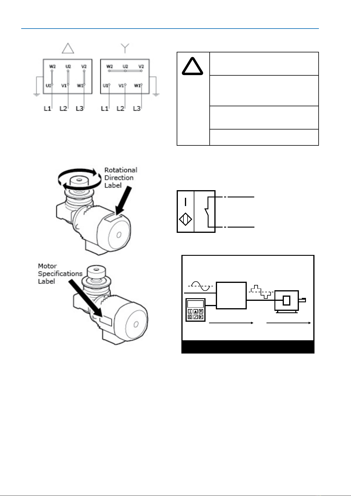
AC Motor Installation
The AC motor in the standard NovAseptic®GMP
ATEX Mixer is three-phase.
1. Connect the drive unit according to the
Variable Frequency Drive (VFD) system
specifications. The drive unit can be Y- or
∆-connected, depending on the supply
voltage from the variable frequency drive.
NovAseptic® GMP ATEX Mixer 13
2. Ensure that the supply voltage and
overload protection are set according to
the motor specification data. Ensure that
the electrical cover and the conduit entries
are properly in place. Check that the outer
drive head rotates clockwise.
Drive Unit Thermistor
All standard NovAseptic® GMP ATEX drive units are
equipped with two positive temperature coefficient
(PTC) thermistor probes. EMD Millipore recommends
installation of the probes. Thermistor protection
units continuously monitor the temperature of the
motor through a probe embedded in the motor
windings. If the nominal operating temperature of
the probe is reached, a rapid increase in resistance
is converted into a switching function. This can be
used to switch off the motor or to signal a fault.
Accidental breaks in the supply circuits of the
thermistors are also detected.
Motor current higher than recommended could
cause damage to the bearings through decoupling
of the mixing head.
Revolution Counter
!
Observe laws, regulations and/or
standards governing the use, or
intended use, of this equipment.
Any alteration of this equipment
from factory specification may
cause unsafe conditions and will
void the product warranty.
The tachometer must be
connected to an intrinsically safe
barrier.
Do not damage the sensor.
Connection
Connect the socket using the following electric
scheme.
N/N0
1/BN
2/BU
L+
L-
Variable-Frequency Drive
Sine Wave
Power
Operator
Interface
VDF System
Power Conversion
Variable
Frequency
Power
Variable
Frequency
Controller
Mechanical
Power
AC Motor
1540
Power Conversion
A variable-frequency, adjustable-speed drive
(VFD) controls the rotational speed of an
alternating current (AC) electric motor by
controlling the frequency of the electrical power
supplied to the motor. VFDs are also known as
adjustable-frequency drives (AFD), variable
speed drives (VSD), AC drives and inverter
drives.
When starting a motor, a VFD initially applies a
low frequency and voltage to the motor.
A VFD increases the applied frequency and
voltage at a controlled rate and accelerates the
load without drawing excessive current.
14 Installation and User Guide

NOTE
Consult the parameter settings and
circuit and terminal diagrams before
installing the control cabinet.
Validate the current media and
process conditions. If the production
conditions are in any way altered after
commissioning of the mixer, a new
validation must be performed.
Validate the possible minimum and
maximum operating speed for each
process.
Catalog
Number
Design Speed (rpm)
NOTE: Design Speed is the
Mechanical Limit
AX05/41 50 – 400
AX1/41 50 – 400
AX5/41 50 – 400
AX10/41 50 – 400
AX20/41 50 – 400
AX50/41 50 – 400
AX100/41 50 – 400
AX200/41 35 – 280
!
Set VFD unit to 100% nominal
power (kW) and current (A) of the
motor rating.
Excess force may cause magnetic
decoupling.
Electric motors (and VFD system
parts, i.e. sensors) when working
with driven equipment are capable
of causing an explosion in an
explosive atmosphere. Consider
this when selecting parts for the
system in ATEX environment.
Operation
!
Ensure that the installation has
been performed correctly and
that the parameters are correctly
programmed.
Ensure that no one is working
inside the vessel.
Ensure that a sufficient level of
liquid covers the mixing head
and the male bearing to ensure
sufficient lubrication of the
bearing.
The mixing head must be covered with
liquid during operation with explosive
media.
Never work close to the drive unit
while it is connected to its driving
source. Keep away from moving
parts.
Regulate speed, acceleration, and
deacceleration carefully to avoid
magnetic decoupling.
Stop the mixer immediately if any
signs of malfunction, abnormal
noise, or smell occurs.
Do not exceed operation
temperature of 135 ºC (275 ºF)
inside vessel.
Use extra precaution because of
pressure buildup when the mixer is
running at high speed and:
• with hot WFI
• at atmospheric pressure
• during or after steam
sterilization
Starting the Mixer
1. Fill the vessel to a minimum level that
completely covers the mixing head and
the male bearing to provide sufficient
lubrication of the bearing.
2. Start the mixer and slowly increase to
a minimum speed (50 rpm). (Note: the
first time the mixer is started, run it for a
few seconds at this speed and check that
the motor fan is turning in the correct
direction.)
3. Increase the speed slowly to working
speed. If the mixer makes a rumbling
noise, stop the mixer immediately and
consult the troubleshooting section in this
user guide.
NovAseptic® GMP ATEX Mixer 15

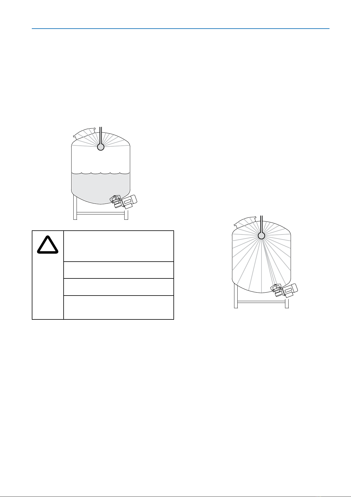
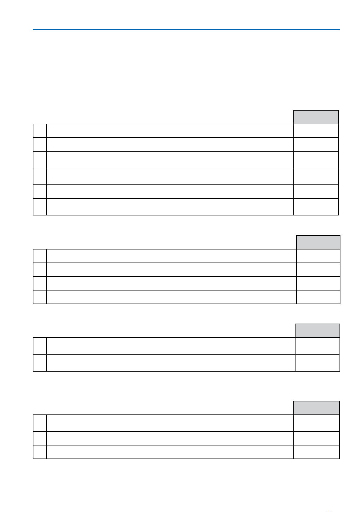
Operating Notes
• Fill the vessel with liquid before adding solid
material.
• Always ensure that the mixing head is
always completely covered with liquid
during all ATEX operation.
• For ATEX operation during draining, stop
the mixer before the liquid level reaches
below the top of the mixer. This will ensure
the mixer is not run dry. If the mixer has
been run dry, turn off the mixer and inspect
the bearings. Consult the troubleshooting
section.
• Avoid buildup of large quantities of solids on
the bottom of the vessel.
Disassembly
!
Before dismounting the drive unit:
• Ensure that the power supply
is turned off.
• Ensure that the vessel is empty
and ventilated.
• Ensure that the vessel is at
atmospheric pressure.
• Ensure that the vessel is
cooled to below 25 °C (77 °F).
• Ensure that all connected
media is shut off.
Before entering the vessel, follow
the local safety precautions.
The drive unit may be heavy. Use
appropriate equipment to avoid
injury.
Dismount the mixer in the following order to
prevent personal injuries and damage to the
equipment:
1. Drive Unit
2. Mixing Head
3. Male Bearing
Storage
• Do not store in areas exposed to weather or
humidity.
• Always place wood or other non-magnetic
material between floor and product, to
avoid direct contact with the floor.
• For storage periods exceeding 60 days,
protect all coupling surfaces (such as
flanges and shafts on the drive unit) with a
suitable anti-oxidation product (Mobilarma
248 or equivalent).
• For storage periods exceeding 6 months,
turn the rotor outer driving head on the
drive unit every 1–2 months.
Recycle and Disposal
Recycle and dispose of equipment according to
local laws and regulations.
16 Installation and User Guide
Cleaning and Sterilizing
Procedures
Cleaning in Place (CIP)
GMP mixers are designed for CIP using any
of the following processes: sprayball, rotary
jethead, or submerged.
Sprayball and Rotary Jethead Cleaning
!
Start the liquid circulation through
the sprayball or jethead before
starting the mixer to ensure
lubrication of the bearing.
Ensure that the bearings are
continuously lubricated.
Stop the mixer before turning off
the sprayball/jethead function.
Add liquid before running the
mixer after cleaning to ensure
lubrication of the bearings.
NOTE
Recommended maximum speed of
the mixing head is 100 rpm.
Submerged Cleaning
Introduce enough cleaning or rinsing liquid into
the vessel to cover the mixing head and the
male bearing.
NOTE:
Avoid vortex.
Add liquid before running the mixer
after cleaning to ensure lubrication of
the bearings.
Magnetic Particles:
If presence of magnetic particles is
suspected, remove the mixing head.
Remove the particles and reinstall the
mixing head. (Refer to Male Bearing
Installation, Mixing Head Installation,
and Drive Unit Installation in this
manual.)
Magnetic particles are not removed
from the mixing head during CIP;
they must be removed manually or by
alternative cleaning. Magnetic particles
can cause corrosion and damage. They
can also cause a higher torque, which
may cause the mixing head to decouple
and severely damage the vessel.
Sterilizing in Place (SIP)
GMP mixers are designed for SIP.
Sterilization by Pressurized Steam
The mixer can be intermittently operated
during the initial condensate phase of the
sterilization sequence up to 100 °C (212 °F).
Recommended maximum speed of the mixing
head is 50 rpm for no longer than 30 seconds.
NOTE
Ensure that condensate lubricates the
bearing surfaces.
Recommended maximum speed of the
mixing head during sterilization is 50 rpm.
Turn the mixer off when the
temperature reaches 100 °C (212 °F).
Add liquid before restarting the mixer
after sterilization to secure lubrication
of the bearings.
Magnetic Particles
If presence of magnetic particles is
suspected, remove the mixing head.
Remove the particles and reinstall the
mixing head. (Refer to Male Bearing
Installation, Mixing Head Installation,
and Drive Head Installation in this
manual.)
Magnetic particles are not removed
NovAseptic® GMP ATEX Mixer 17

from the mixing head during CIP;
they must be removed manually or by
alternative cleaning. Magnetic particles
can cause corrosion and damage. They
can also cause a higher torque, which
may cause the mixing head to decouple
and severely damage the vessel.
Other Sterilization Methods
For information on using other sterilization
methods, please contact your EMD Millipore
representative for NovAseptic®GMP ATEX Mixer
product information.
18 Installation and User Guide
Installation ATEX Checklist
To ensure correct installation, before using the mixer make sure to complete each step in this
checklist, and check the applicable box.
Note:
Follow all installation recommendations, cautions and warnings in this manual.
Install the Male Bearing
Complete
1Ensure the proper position of the O-ring on the male bearing. qyes qno
2Lubricate the O-ring with purified water. qyes qno
3Ensure that the thread connection in the tank plate is clean, dry, and free from
foreign material. qyes qno
4Position the male bearing in the appropriate tightening tool or
multi-tool. qyes qno
5Tighten the male bearing clockwise. qyes qno
6Tighten the bearing to metal-to-metal contact; use table to determine correct
torque. qyes qno
Install the Mixing Head
Complete
1Inspect and remove any foreign magnetic particles from the mixing head. qyes qno
2Remove the drive unit. Install the mixing head. qyes qno
3Position the mixing head and align it with the tank plate. qyes qno
4Ensure that the mixing head rotates smoothly. qyes qno
Before Installing the Drive Unit
Complete
1Verify that the drive unit classification noted on the product label (G or D or
GD) is matches the installation. qyes qno
2Turn on the motor. Verify that the drive head rotates clockwise and that the fan
rotates counterclockwise. qyes qno
Install the Drive Unit – GMP 50 ATEX, GMP 100 ATEX, GMP 500
ATEX
Complete
1Install the drive unit into the tank plate; put the two studs on the tank plate
into the slots on the drive unit. qyes qno
2Turn the drive unit clockwise (view from below) to the stop position. qyes qno
3Tighten the two nuts with a wrench. qyes qno
NovAseptic® GMP ATEX Mixer 19

Install the Drive Unit – GMP 1000 ATEX and GMP 2000 ATEX
Complete
1Fit screws and tighten clockwise (view from below). qyes qno
2Install the drive unit into the tank plate. Install locking screws into the two oval
holes in the tank plate. qyes qno
3Turn the drive unit clockwise (view from below) to the stop position. qyes qno
4Tighten the two screws clockwise (view from below). qyes qno
Install the Drive Unit – GMP 5000 ATEX, GMP 10000 ATEX, GMP
20000 ATEX
Complete
1Install the drive unit into the tank plate. Align the four holes in the drive unit to
the threaded holes in the tank plate. qyes qno
2Screw the four bolts into the tank plate and tighten. qyes qno
Before Installing the Electrical Components
Complete
1Ensure all incoming power is equipped with an emergency stop and an on/off
switch. qyes qno
2Shield motor cables. qyes qno
3Ensure the drive unit is grounded. qyes qno
4Ensure electrical cables are long enough to enable the drive unit to be
disassembled and removed from the vessel. qyes qno
Install the AC Motor
Complete
1Connect the drive unit. qyes qno
2
Ensure that the supply voltage and overload protection are set. Ensure that the
electrical cover and conduit entries are in place. Ensure that the outer drive
head rotates clockwise (view from above).
qyes qno
Install the Revolution Counter
Complete
1Connect the wiring from the tachometer into the appropriate apparatus
according to the proof of intrinsic safety. qyes qno
20 Installation and User Guide
Table of contents
Popular Mixer manuals by other brands

AUSTRALIAN MONITOR
AUSTRALIAN MONITOR AMIS PM4 introduction

ALFA LAMDA
ALFA LAMDA Primo MK-36 User instructions

Brabantia
Brabantia D3 instruction manual

HOMEKRAFT
HOMEKRAFT HKMIXPLROTARY1 user manual

Northern Industrial Tools
Northern Industrial Tools 998255 owner's manual

InoTec
InoTec inoMIX S16 Original operating manual


