Mercoframes Optical Corp Kowa KT-800 User manual

TONOMETER
INSTRUCTION MANUAL
KOWA KT-800 EU/US
1
INTRODUCTION
Accept our congratulations on your purchase of KOWA KT– 800.
ThismanualprovidesadescriptionoftheoperatingproceduresofKT–800alongwithimportantprecautions
to be observed during its use. Please read this entire manual carefully to assure that the instrument can
demonstrate its full capabilities and be used effectively. After you have finished reading it, please keep it in
an easily accessible location near the instrument for future's reference.
Operational considerations for safety
Thismanualdescribes important precautions to be observed during its use to assure that the instrument can
be used safely without causing any damage to the human body and property of its purchaser and other
persons. The designations and their pictorial symbols have the following meanings. These should be fully
comprehended before reading the text of this manual.
■Meanings of markings
■Kowa is not responsible for:
•Any damage caused by fire, earthquake, third party’s action, any other accident or user’s intentional
or unintentional error, abuse or use under abnormal conditions;
•Any damage resulting from use of the product or its malfunction (e.g. Operating loss, shutdown,
change/loss of stored data and so forth).
•Any damage resulting from disobedience of what is described in the instruction manual.
•Any damage resulting from, for instance, malfunctioning of the instrument caused by a combination of
connected devices.
Graphical indication of any danger (including warning and caution). What is warned is explicitly and
pictorially indicated by a picture or its associated message on or near a pictorial symbol.
Graphical indication of prohibited operation (prohibitive item). What is prohibited is explicitly and pictorially
indicated by a picture or it's associated message on or near a pictorial symbol.
Graphical indication of mandatory action (obligatory item). What must always done is explicitly and
pictorially indicated by a picture or it's associated message on or near a pictorial symbol.
INTRODUCTION
*1: An injury to the human body means any injury, burn, electrical shock and so forth that will not
necessitate hospitalization or long-term outpatient treatment.
*2: Damage to property means an extensive damage to the house and household goods as well as the
domestic animal and pet
■Meanings of symbols
If the instrument should be operated wrongly, there may occur a danger of causing death or serious injury.
If the instrument should be operated wrongly, there may result an injury to the human body (not so serious as to cause death
though)*1or damage to property*2.
WarningWarning
CautionCaution
2
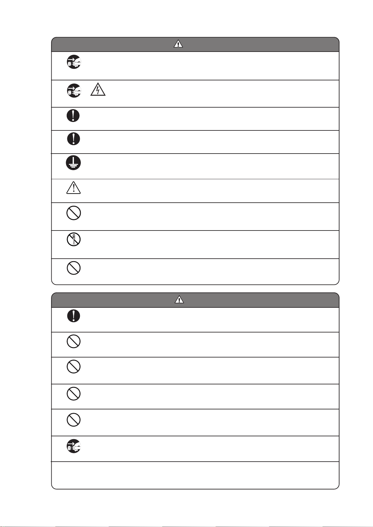
If any abnormal smell or sound, or overheating or smoke should be detected, be sure to turn OFF power
supply immediately and then unplug it from the power outlet. If it should continue in use, a fire may break out
on the instrument resulting in its malfunctioning.
Contact your Kowa dealer where you purchased it or your nearest repair shop for inspection.
When replacing the fuse, be sure to turn OFF the main switch and unplug it from the power outlet.
If the fuse holder cover is removed with the instrument unplugged, there may occur electrical shock.
Be sure to properly plug the plug or AC adapter into the power outlet.
Otherwise, there may occur a fire or electrical shock.
Use an accessory or designated fuse.
Otherwise, the instrument may malfunction or a fire may break out.
Make sure that the instrument is properly grounded to protect the human body. Put the plug in the three-wire
grounding type socket. Otherwise, there may occur electrical shock.
Unplug
Unplug
Install at a location away from, for instance, a cup containing liquid.
If liquid should be spilled into the instrument, there may occur electrical shock. If so, turn OFF the instrument
and then unplug it from the socket. Contact your Kowa’s dealer where you purchased it or your nearest repair
shop for inspection.
Do not disassemble, modify or repair the instrument yourself. Otherwise, there may occur a fire, electrical
shock, instrument malfunctioning or the human body may be injured.
Contact your Kowa dealer where you purchased the instrument for repair. The product assembled by yourself
will not get warranty or any other service.
The socket or plug board must not be loaded in excess of its rated capacity.
If the main power cord should share a power outlet with many other devices, there may occur a fire or electrical
shock.
Be sure that the tips of instrument are not in contact with the eye and the nose when in operation. (Otherwise,
the patient may likely be injured.)
High-voltage
Warning
Pull off the plug from the power outlet without giving a pull.
Do not plug or unplug the power cord with wet hand.
Do not install the power unit at unstable locations, for instance, on a shaky base or a tilting surface.
Otherwise, if it should drop off or fall over, the human body may be injured.
Do not wipe the exterior of the instrument with solvent such as benzene, alcohol, thinner and ether since such
substances may cause discoloration or degradation.
Prohibitory
Prohibitory
Prohibitory
Obligatory
The power supply must be provided for the sole use of this instrument.
If it shares one and the same power supply with any external instrument, KT-800 may malfunction.
Prohibitory
If the instrument is intended to be not in use for a long period of time, unplug the power cable. Otherwise, a fire
may occur on it.
WarningWarning
CautionCaution
Federal law restricts this device to sale by or on the order of a Physician or Practitioner for US market.
Prohibitory
Disassembly
prohibited
Prohibitory
Warning
Obligatory
Obligatory
Obligatory
Unplug
3
Before replacing fuse, be sure to turn the POWER switch OFF and
pull out the plug from the receptacle.
If you remove the cover of fuse without pulling out the plug, it
creates a risk of electrical shock.
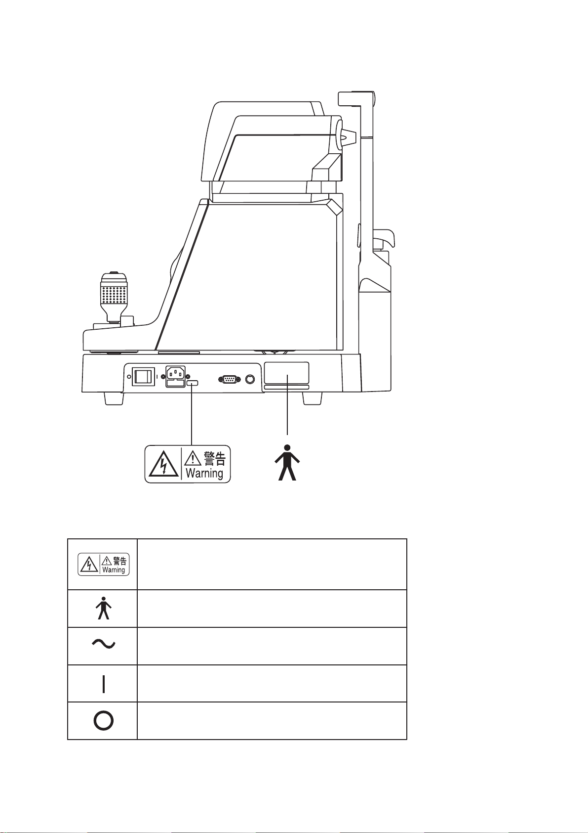
Type B applied parts (degree of protection of applied part against
electric shock)
Alternative Current
ON
OFF
Description of Labels and Symbols
Location of Cautionary Marking
4
Precautions in operation
•When handling the Tonometer, pay special attention
not to give strong shock to it.
•The instrument should be Installation, Transportation,
Storage in a dust free place free from high
temperatures, high humidity and direct sunlight. The
environmental conditions described below should be
observed strictly.
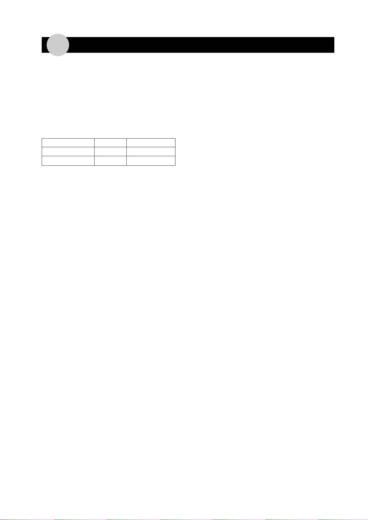
In operation
Transportation, storage
Environmental Temperature
10~40°C-15~+60°C
Relative
Humidity 30~75% 10~95%
•When in use, in storage or in transit, care must be
used to keep the instrument from dewing.
•Always cover the system when not use to protect its
components.
Precautions concerning use of the
electrical system
•Install the system in a location where there is little risk
of the plug being pulled out. If the plug should happen
to be pulled out, only plug it back in after first turning
off the main switch.
•The manufacturer is not liable for malfunctions or
injuries resulting from maintenance or repairs
performed by persons other than the specified repair
service.
•The manufacturer is not liable for malfunctions or
injuries resulting from modification, maintenance or
repairs using parts other than the specified repair
parts.
•The manufacturer is not liable for malfunctions or
injuries based on results obtained by not observing
the cautions or operating procedure described in this
instruction manual.
•The manufacturer is not liable for malfunctions or
injuries caused by use of this system under ambient
conditions that deviate from the conditions of use of
this system, including the power supply and
environmental conditions, as described in this
instruction manual.
•The manufacturer is not liable for malfunctions or
injuries caused by fire, earthquake, flood, lightning or
other natural disasters.
•The input voltage should always be maintained within
±10% of the rated voltage.
•Wait approximately 5 seconds (until the power supply
stabilizes) after turning on the main switch before
operating any of the panel switches.
•Do not turn the main switch on and off in succession.
Allow an interval of at least 4 seconds before turning
the main switch on and off.
•Makesuretoturn thepower switchoff beforeinserting
or removing any plugs.
Precautions concerning use of the main
unit
•The non-contact tonometer used by this system is
designed for screening purposes. Measured values
may contain error depending on the particular
conditions of use. When measured values are
questionable, it is recommended to perform a more
precise examination using an applanation tonometer.
•The printer used by this system produces the best
results when used within a temperature range of 10-
40°C and humidity range of 30-75%. Please do not
use the paper in environments outside these ranges.
•Due to nature of the paper used, long-term storage
can cause it to deteriorate. When desiring to store
printed results for a long time, it is recommended to
first copy them onto ordinary copier paper prior to
long-term storage.
•Perform the following inspections when resuming use
of the system after not using for a long time.
-Inspect soiling of the air nozzle surface.
-Inspect the inside of the air nozzle begin operations
on controls and switches on the operation panel.
-Setting of a date by menu mode.
•Turn power switch off before unplugging or plugging
of power cord.
Disposal Precautions
•When disposing of this instrument, comply with the
regulations of countries or areas in which the
instrument is used.
Other precautions:
•Kowa shall not be responsible for:
-Failure or damages caused by modifications, repair
or maintenance conducted by any party other than
Kowa and its authorized distributor(s), and
-Failure or damages caused by modifications, repair
or maintenance using any parts other than those
designated by Kowa.
•Never disassemble nor adjust this instrument by
yourself since it uses precision parts which requires
special tool for doing so.
Precautions Concerning Use

5
Precautions Concerning Use of Medical Electrical Equipment
1. Equipment should only be operated by qualified personnel.
2. The following items must be observed when installing equipment.
(1)Install in a location free of moisture.
(2)Install in a location where there is no risk of detrimental effects caused by air pressure, temperature,
humidity, ventilation, sunlight, dust, salt or air containing sulfur and so forth.
(3)Install the equipment in a stable manner while paying attention to inclines, vibrations and shock
(including that during transport).
(4)Do not install in locations where chemicals or pharmaceuticals or stored or where there is generation of
gas.
(5)Use the proper power supply frequency, voltage and allowable current values (or power).
(6)Confirm the status of battery-powered power supplies (degree of discharge, polarity, etc.).
(7)Make sure the equipment is properly grounded.
3. The following items must be observed before using the equipment.
(1) The equipment must be inspected for switch contact, polarity, dial settings and meter readings to confirm
that is operating properly.
(2)Confirm that the equipment is properly grounded.
(3)Confirm that all cords are properly and securely connected.
(4)Avoid combined used of equipment since this can lead to errors in accurate diagnoses and danger.
(5)Re-inspect any external circuits that come in direct contact with patients.
(6)Check any battery-operated power supplies.
4. The following items must be checked during use of the equipment.
(1)Do not exceed the time or quantity required for diagnosis or treatment.
(2)Continuously monitor the equipment for any abnormalities as well as the status of the patient.
(3)When an abnormality is noticed in the equipment or patient, appropriate measures must be taken such
as terminating operation of the equipment while ensuring the safety of the patient.
(4)Do not allow the patient to touch the equipment.
5. The following items must be observed following use of the equipment.
(1)Turn off the power after first returning all operating switches, dials and other components to their status
prior to use in accordance with the specified procedure.
(2)When pulling out cords, pull out the cord while holding onto the plug body so as not to apply excessive
force to the cord itself.
(3)The following items must be observed with respect to the location where the equipment is stored.
(a)Store in a location free of moisture.
(b)Store in a location where there is no risk of detrimental effects caused by air pressure, temperature,
humidity, ventilation, sunlight, dust, salt or air containing sulfur and so forth.
(c) Store the equipment in a stable manner while paying attention to inclines, vibrations and shock
(including that during transport).
(d)Do not store in locations where chemicals or pharmaceuticals or stored or where there is generation
of gas.
(4)Store all accessories, cords, leads and other components in an organized manner after cleaning.
(5)Always make sure to clean the equipment so that it functions properly the next time it is used.
6. In the event equipment should malfunction, the operator should not attempt to correct the problem, but
rather appropriately indicate that the equipment is not operating properly and await repairs by qualified
personnel.
7. Never attempt to disassemble or modify the equipment.
8. Maintenance and Inspection
(1)All equipment and components should be inspected regularly.
(2)When resuming use of equipment that has not been used for a long time, always confirm that the
equipment operates properly and safety before use.
9. Be careful of the possibility that incorrect operation may be caused by strong electromagnetic waves.
This equipment is examined based on IEC 60601-1-2:2001.
The purpose of this standard is to keep safety against the dangerous obstacle in typical medical facilities.
When this equipment is influenced by other equipment, or when it affects other equipment or when there is
such fear, please devise to move this equipment and other apparatus or to make the distance between
those equipment.
Moreover, if there is an unknown point, please consult our company, or an agency beforehand.

6
ACCESSORIES
Power cable: 1 Fuse: 2 Dust protective cover: 1
Disposable paper for Chin rest's pins:2 Printer paper:2
covering chin rest:1
Instruction manual: 1

7
INTRODUCTION ----------------------------------------------------------------------------------1
Precautions Concerning Use ----------------------------------------------------------------4
Precautions
Concerning
Use of Medical Equipment
------------------------------------5
ACCESSORIES------------------------------------------------------------------------------------6
Contents --------------------------------------------------------------------------------------------7
1. Summary of Equipment ------------------------------------------------------------------8
2. Name of Each Part and Functions ----------------------------------------------------9
■Summary of Display ■--------------------------------------------------------------- 10
3. Procedure of Measurement ----------------------------------------------------------- 11
■AUTOMATIC MODE ■---------------------------------------------------------------- 12
■MANUAL MODE ■--------------------------------------------------------------------- 13
4. Measurement Value ---------------------------------------------------------------------- 14
■ERROR message ■------------------------------------------------------------------- 14
■Display of data marked with asterisk* ■--------------------------------------- 14
■ LIMIT OF ACCURACY ■------------------------------------------------------------- 14
5. Printing of measurement results ---------------------------------------------------- 15
■Replacement of Printing Paper ■------------------------------------------------ 15
6. Menu Mode---------------------------------------------------------------------------------- 16
■Startup of Menu Mode ■------------------------------------------------------------ 16
■Selection of Each Item ■------------------------------------------------------------ 16
■End of Menu Mode ■----------------------------------------------------------------- 16
■Description of Each Item ■--------------------------------------------------------- 17
1ID --------------------------------------------------------------------------------------------------------------------- 17
2DATE ---------------------------------------------------------------------------------------------------------------- 18
3AUTO OFF --------------------------------------------------------------------------------------------------------- 18
4ID IN ----------------------------------------------------------------------------------------------------------------- 19
5DATA OUT --------------------------------------------------------------------------------------------------------- 19
6PRINT FORM------------------------------------------------------------------------------------------------------ 19
7WARNING ---------------------------------------------------------------------------------------------------------- 19
8AIR CHECK-------------------------------------------------------------------------------------------------------- 19
7. External Connection--------------------------------------------------------------------- 20
1Ten Key Pad ----------------------------------------------------------------------------------------------------------- 20
2Barcode Reader------------------------------------------------------------------------------------------------------ 20
3Data Control by Personal Computer -------------------------------------------------------------------------- 20
8. Maintenance .Check -------------------------------------------------------------------- 21
1. Daily Check -------------------------------------------------------------------------------------- 21
2. Replacement of Fuse ------------------------------------------------------------------------- 21
3. How to Mount Chin Rest Paper------------------------------------------------------------ 21
4. How to Disinfect Forehead Rest Pad and Chin Rest ------------------------------- 22
5. Supplement of Consumed Expendables----------------------------------------------- 22
6. Periodical Check ------------------------------------------------------------------------------- 22
7. Repair of Equipment -------------------------------------------------------------------------- 22
9. Specification ------------------------------------------------------------------------------- 23
10. Photochemical Hazard ------------------------------------------------------------------ 24
11. Electromagnetic Compatibility (EMC) --------------------------------------------- 25
Contents

8
1. Summary of Equipment
■ Indication for use ■
The KOWA KT-800 is an AC-operated, equipment for measuring intraocular pressure without contact with eye.
■ Features ■
1) You can select 3D or 2D in Automatic Mode for Alignment. You can also select Manual Mode, of course.
2) Alignment information and measurement values after measurement are displayed on 5.6" Color LCD.
3) The measurement values are printed by printer or transferred to personal computer as electronic data.
4) You can enter the patient ID by Ten Key Pad or bar code.
5) Chin rest can be electrically moved up and down.
6) Blink detecting function is provided.

9
2. Name of Each Part and Functions
When operating this equipment, be careful to prevent
your hand from being caught at arrowed location
(marked with ).
NEVER install this equipment so as to block ventilation
opening.
CautionCaution
10
11
11
1Chin rest
A pedestal for carrying the patient’s chin.
22
22
2Locking screw
It fixes pedestal to prevent movement in all
directions.
33
33
3Printer Cover
Replaces printing sheets.
44
44
4✽Clear Switch
It deletes the data marked with ✽(one biggest
value)
55
55
5PRINT Switch
It prints data or transfers data to external devices.
If there is no printed (or transferred) data, the LED of
switch lights.
66
66
6switch
When you press this switch, the Chin rest will goes
up. During the energy-saving mode, the LED blinks.
77
77
7switch
When you press this switch, the Chin rest will goes
down.Duringtheenergy-savingmode,the LEDblinks.
88
88
8Safety Stopper
It restricts the movement of the pedestal to prevent
the measurement nozzle from contact with subject.
99
99
9Forehead rest
It is applied to and holds the subject’s forehead.
00
00
0Air supply nozzle
Air blow is supplied from opening.
AA
AA
AEye Level Mark
It indicates the standard level of the subject’s eyes.
BB
BB
BMeasurement Switch
When you press this switch, air is blown and the
equipment measures the intraocular pressure.
CC
CC
CJoy Stick
You can move the main body in all directions. If you
turn the joystick, the main body will goes up and down.
DD
DD
DDisplay
5.6” TFT LCD Monitor is used. It displays the
alignment of front part of eyes and measurement data.
EE
EE
EAUTO/MANUAL Switch
It switches measurement mode.
FF
FF
F3D/2D Switch
When the measurement mode is automatic, it
switches 3D/2D. For 3D, alignment can be
automatically made within ±2mm in forward/
backward direction.
GG
GG
GMENU Switch
When you keep pressing this switch for more than 1
second, you can call Menu Mode of various setting.
HH
HH
HCLEAR Switch
It clears data.
II
II
IVentilation Opening
JJ
JJ
JExternal Input Terminal
Connect Ten Key Pad and Barcode Reader for ID
Input to this terminal.
KK
KK
KExternal Output Terminal
This terminal is used for output of personal computer.
LL
LL
LPower Inlet
Fuseholder is provided.
MM
MM
MPower Switch
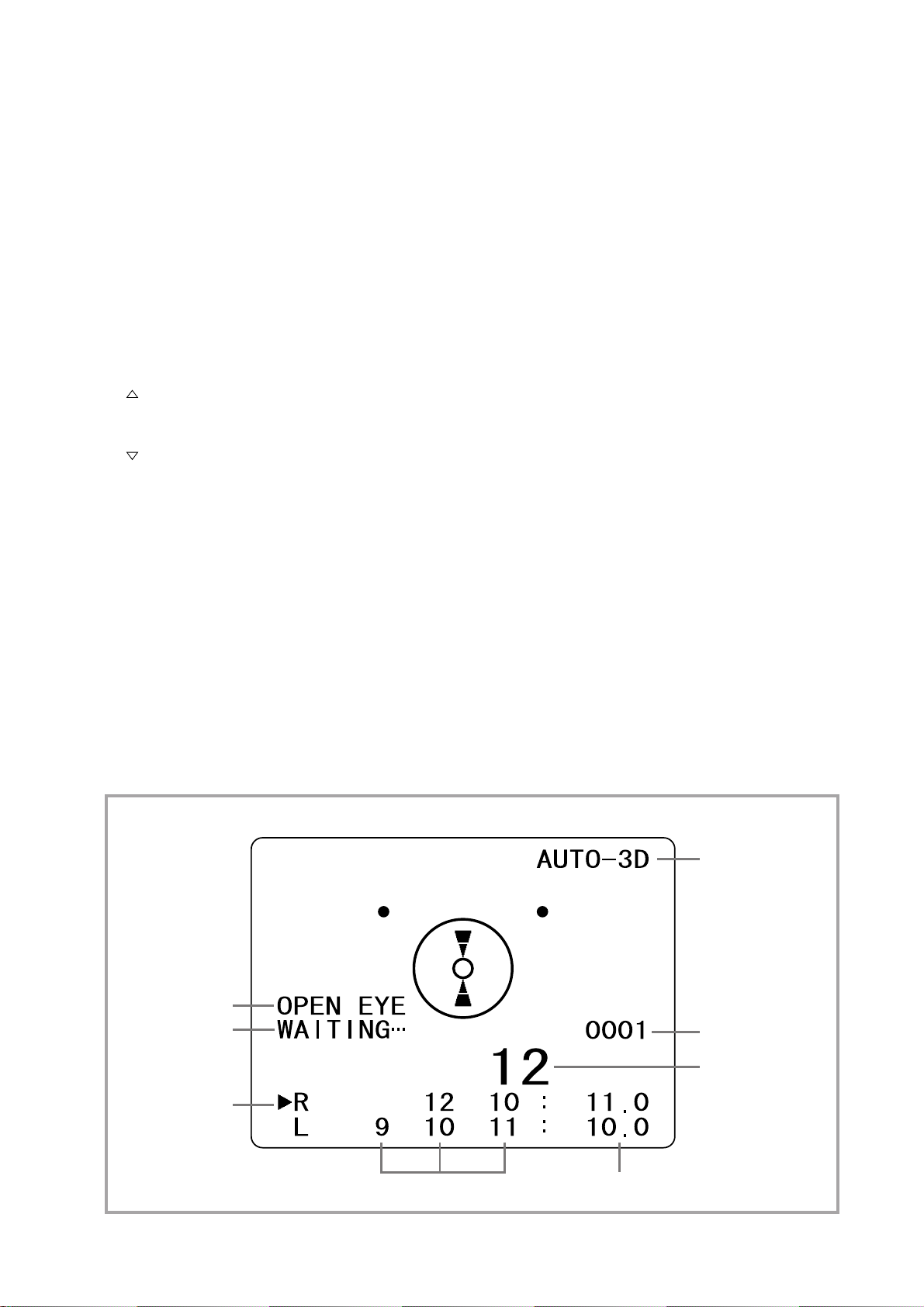
■ Summary of Display ■
This message
appears for a moment
after measurement.
This message
appears when the
subject’s eye is not
opened sufficiently.
The subject’s eye
being measured is
shown by arrow.
Current Measurement
Mode
The measurement
value is shown with
magnification for a
moment after
measurement.
The measurement values
are shown. The average values are shown.
ID number
11
1. Operate the joystick and move the pedestal to the position on this
side where the pedestal stops.
2. Fix the subject’s chin and forehead to the eye level mark on the
forehead rest frame.
Instruct the subject to put his/her face to chin rest and forehead
rest.
•Press or key to move the Chin rest up or down and adjust the
level of the subject’s eyes to the eye level mark.
3. Keep pressing the safety stopper and make the pedestal closer to
the subject slowly.
Then adjust the distance between the subject’s eyes and air supply
nozzle within 11mm.
To avoid contact of the subject’s eyes with air supply opening, be
sure to check the distance between the subject’s eye and air
supply nozzle from the side of the equipment.
•If you take your hand off from the safety stopper,the safety stop
function is activated.
•Proceed to the next step after first checking that the frame does
not move any closer to the subject's eye..
Clean the glass part of air supply nozzle on regular basis. If the glass part is stained by contact with the subject’s
eyelashes or stuck dust, you cannot do the measurement correctly. When cleaning, apply a small amount of alcohol
to soft gauze or silbourne paper (lens cleaning paper) and wipe the glass part with it twice.
During the cleaning, be sure not to touch the hole of nozzle of air supply nozzle.
4. Move the pedestal to the operator’s side by joystick.
•Move the pedestal by joystick in all directions so that the front of the subject’s eyes are displayed on the
screen.
If you turn the joystick, the displayed area moves up and down.
At this time, the subject sees the green fixation light. Draw the subject’s attention to stare at it.
5. Keep looking at the screen and make the air supply nozzle closer to the subject’s side.
•At this time, instruct the subject to look at the green point in the nozzle of air supply.
To clean the inside of the nozzle, press measurement switch and do the empty shooting a few times before use. At
this time, make sure that there is nobody in front of the nozzle.
3. Procedure of Measurement
2Eye level Mark
3
Safety stopper
Caution
Caution
Caution
Caution
Caution
Caution
12
■ AUTOMATIC MODE ■
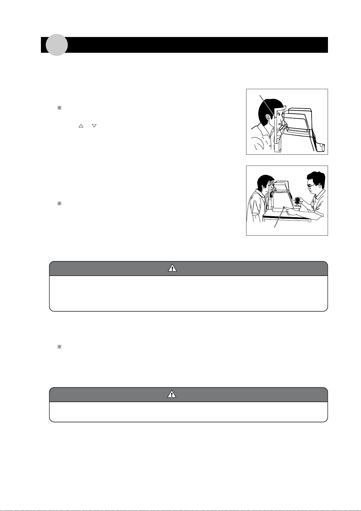
6. You will see 3 brilliant points on the corneal as shown in the
figure on the right. Move the joystick in all directions so that
the alignment brilliant points inclined to the center will be
covered in the outer circle of double circle.
•When the brilliant points are within the circle, automatic
alignment function in all directions is activated.
7. While checking the alignment brilliant points are at the center
of the double circle, make the pedestal closer to the subject by
joystick.
8. The trapezoid appears on the screen as shown in Figure A, make it closer to the subject by joystick. When
the alignment is getting better, the screen will be changed as shown in Figure B, and air blow is shot
automatically and measurement is made.
If the display is as shown in Figure C, the measurement nozzle is too close to the subject’s eyes. You hear
alarm sound “Beep” and keep apart the nozzle from the subject’s eye by joystick.
9. If you select 3D in automatic mode, automatic alignment in forward/backward direction is activated when the
display becomes as shown in Figures A and C.
If the display as shown in Figure B does not appear or air blow is not shot due to fixation is bad or the
shape of corneal is not good, you can do the measurement by pressing measurement switch as well as
manual mode.
Brilliant Alignment Point
Figure A Figure B Figure C
Figure D Figure E

13
•If the alignment display does not appear on the screen, alarm does not sound even if the nozzle becomes closer
to the subject’s eyes.
• In the Menu Mode, if the WARNING is set to OFF, alarm does not sound.
•Alarm sound stops in a short time even if the nozzle does not separate from the subject’s eyes. When the alarm
sounds, draw the nozzle to the operator side and separate the nozzle from the subject’s eyes.
•The warning for approaching by alarm sound is just for supplemental purpose. Be sure to use safety stopper for
safe measurement.
•If the subject does not open his/her eyes sufficiently, intraocular pressure cannot be measured correctly.
Therefore, if the opening of eyes is not enough, a message “OPEN EYE” appears on the screen. At this time, in
automatic mode, measurement cannot be made even if the display is as Figure B. Until either one of upper 2
brilliant points can be seen, instruct the subject to open his/her eye or you open his/her eye by hand.
■ MANUAL MODE ■
6. You will see 3 brilliant points on the surface of corneal as
shown in the right figure.
Move the joystick in all directions so that an brilliant alignment
point inclined to the center comes to the center of doubled
circle.
7. Keep the brilliant point to the center, and make the nozzle
closer to the subject by joystick slowly.
• As well as Automatic Mode, make the nozzle closer to the
subject by joystick until the display becomes as shown in
Figure B of the previous page.
8. Check the alignment display and press the Measurement switch.
•Air blow is shot and measurement will start.
Brilliant Alignment Point
Caution
Caution
Caution
14
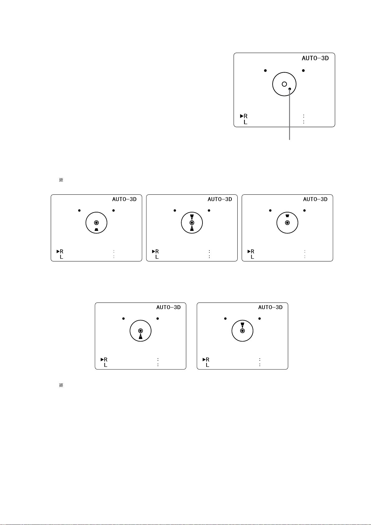
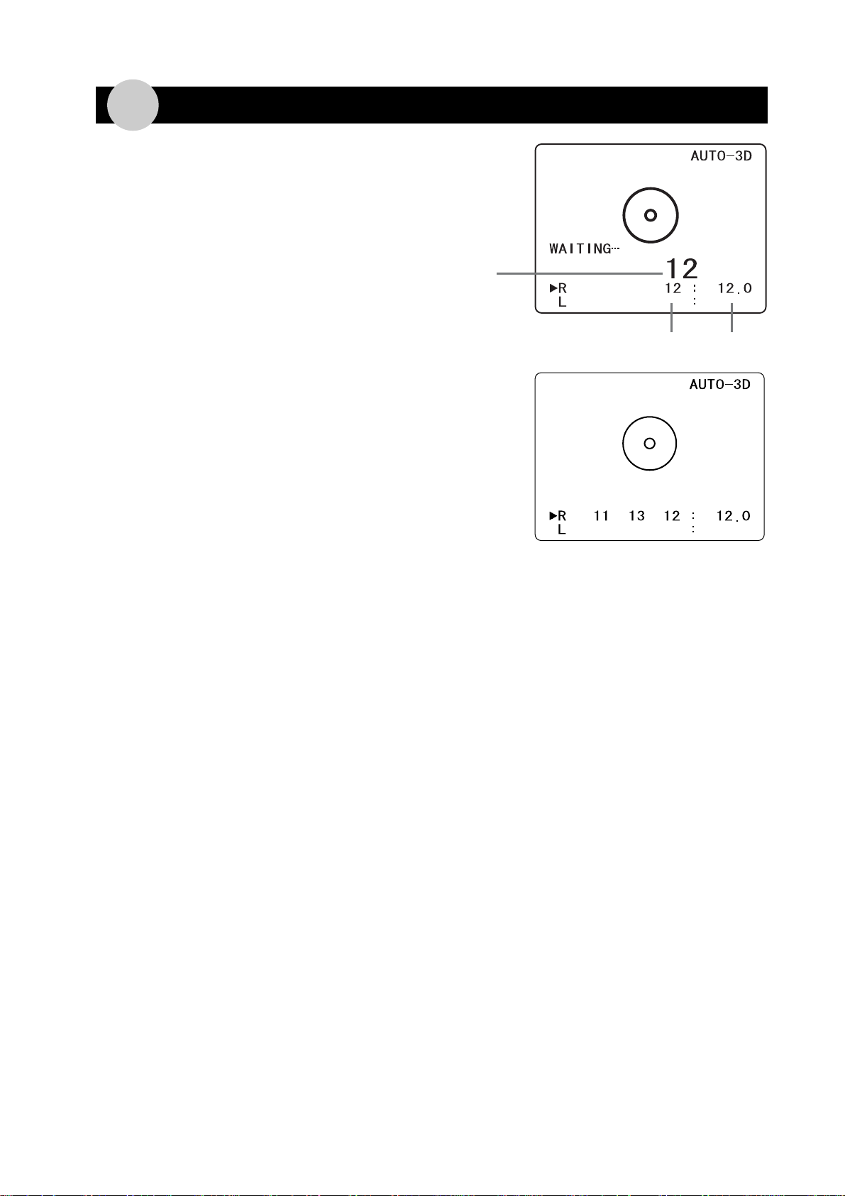
4. Measurement Value
When the measurement is made, the measurement value will be
displayed on the screen as shown in the right figure.
After measurement, the measurement value will be displayed with
magnification for a moment. Moreover, a message “WAITING” will
appear on the left of the screen.
Measurement is made more than 2 times and the average of 3
measurement values is taken as the intraocular pressure.
(Intraocular pressure varies with time according to factors such as
breathing and pulse. By taking the average of 3 measurement
values, such factors are offset.)
■ ERROR message ■
When the measurement was not made correctly,
“ERROR” message is displayed for a moment.
While this message appears on the screen,
the next measurement cannot be made.
✽The causes of ERROR which can be considered are:
1bad fixation, 2blink, and 3extremely abnormal shape of corneal.
■ Display of data marked with asterisk* ■
Though measurement was done, but if the reliability of data is low, the measurement value will be displayed with “✽” mark.
Open the subject’s eyes and fix his/her sight, then do the measurement again. The value with "✽" mark is not used for the
average calculation.
■ LIMIT OF ACCURACY ■
Degree of accuracy claimed for devices with a measuring function.
±1mmHg:more than 0 and less than 30mmHg
±2mmHg:more than 30, 60mmHg or less
Average
Measurement Value
Measurement
Value
15
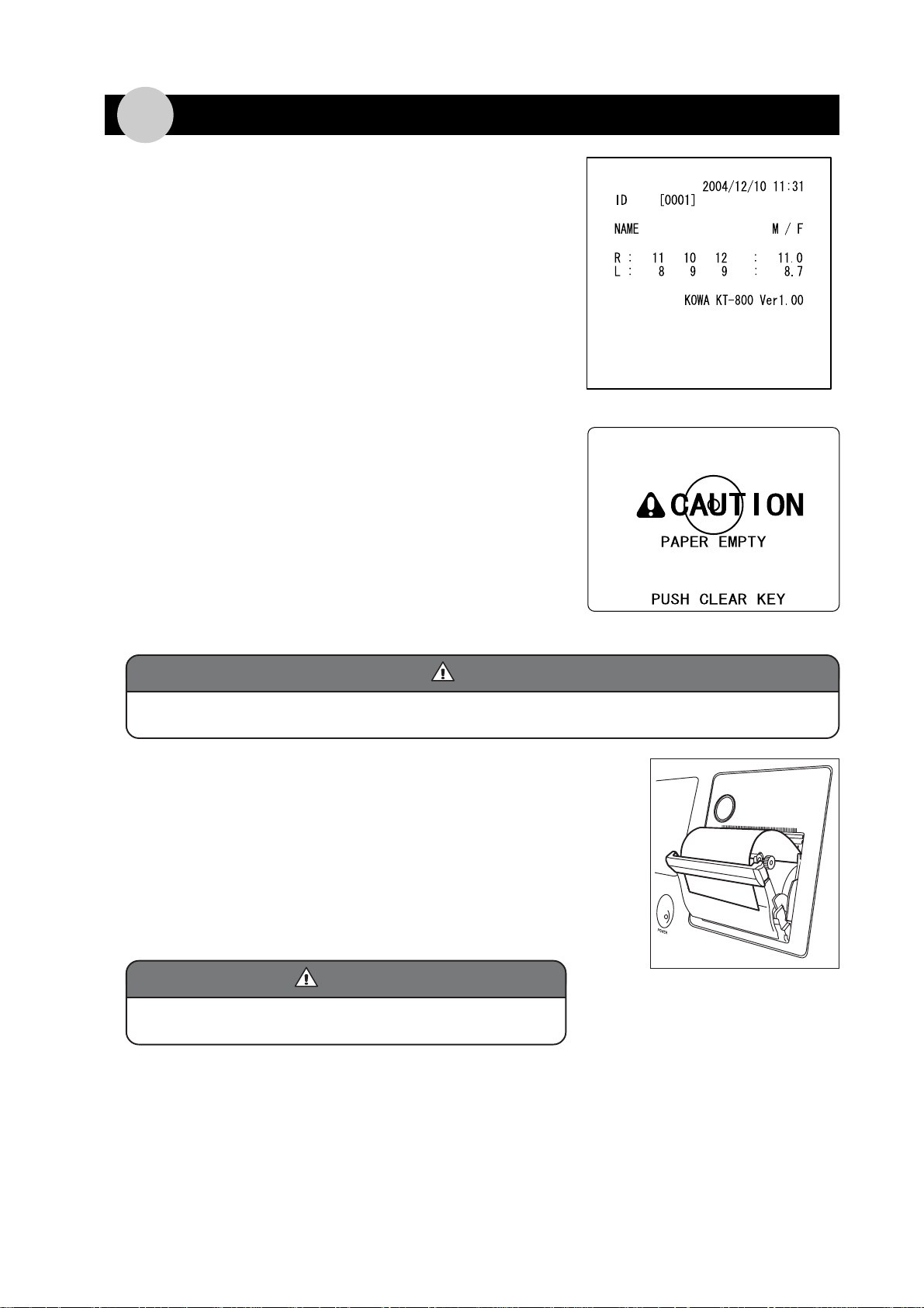
5. Printing of measurement results
When you press the PRINT switch, the data measured up to that
time is printed. Once printing is finished, the data is deleted.
If needed, write the items "NAME" and sexuality "M/F" by hand after
the data is printed onto paper.
When you press the PRINT switch and if there is no printing paper,
the message on the right will appear.
When you press the CLEAR switch, the display will return to the
normal measurement screen. Until paper is supplied, “PAPER END”
message will appear on the left top of the screen.
■ Replacement of Printing Paper ■
Before replacement of printing paper, make sure that the subject’s chin is placed on the chin rest.
During the replacement of paper, the pedestal can be put out to the subject side.
1. Press the button with green round rim on the printer part.
The cover will open.
2. Supply new printer paper into the printer.
3. Pass a piece of printing paper through the printer cover.
4. Close the printer cover, and cut the excessive paper.
Replacement of paper is finished.
Be careful with the inside and outside of printing paper. If it is failed,
nothing is printed on it.
4
Caution
Caution
Caution
Caution
Caution
Caution

16
6. Menu Mode
This is a Mode for various settings of KT-800.
■ Startup of Menu Mode ■
Keep pressing Menu Switch for more than 1 second.
When the Menu Mode starts up, the display on the right will appear.
■ Selection of Each Item ■
Select each item by or switch.
Then when you press AUTO/MANUAL switch, selected item is fixed.
When you press PRINT switch in Menu Mode, the set items of
menu are printed out.
■ End of Menu Mode ■
If you select END and press AUTO/MANUAL switch, the display returns to normal measurement mode.
Battery is installed inside to maintain the date and contents of set items
of the Menu Mode.
Thebattery lasts4-6 monthswhen itis fully charged(for about12 hours),
but for charging, turn the POWER switch ON for more than 30 minutes
every week.
When the battery is exhausted, the date and the values set by Menu
Mode return to the initial value. Set the value again.
Caution
Caution
Caution

17
■ Description of Each Item ■
1ID
When you select the ID, the following display appears.
ID Number Setting Mode
[ID ON/OFF]
You can set ON/OFF of display of ID number on this menu.
In case of ON : “ID number” appears as shown below. If the PRINT FORM of the Menu Mode is REGULAR,
the “ID number” is printed. When printing is done, 1 is automatically added to “ID number”.
In case of OFF : If the PRINT FORM of the Menu Mode is REGULAR, the printed ID number will be blank as
“ID[ ]”. Use this function when you want to enter the ID number by hand.
3D/2D switch/MENU switch : Selection of digit of ID value
• switch : Up/Down of ID value
AUTO/MANUAL switch : ENTER
CLEAR switch : Value cleared
Initial value : 0001
ID Number Display ON/OFF Mode
Returns to the first display of Menu
switch : ON
switch : DOWN
AUTO/MANUAL : ENTER
ID number
[ID SETTING]
You can set the ID number on this menu.

18
3AUTO OFF
This menu is to set energy-saving mode. The initial value is “ON”.
ON : If the KT-800 is not operated for a certain time, the monitor will be turned OFF and shifting over to
energy-saving mode (about 5 minutes).
Energy-saving mode is released when you press any switch.(not released by turning joystick) Data
before entering energy-saving mode is saved.
OFF : The KT-800 is not shifting over to energy-saving mode.
2DATE
When the DATE is selected, the following display appears. This is the mode to set the “DATE” and type of
“FORMAT”.
[DATE SETTING]
Date Setting Mode
[DATE FORMAT]
DATE FORMAT Mode
This menu is to set the format of date which is printed in case of printing the measurement data.
Date Setting Mode
Date Format Mode
Returns to the first display of MENU
Japan
U.S.A.
Europe
3D/2D switch/Menu Switch : for setting the date
• switch : for increase and
decrease of value
AUTO/MANUAL Switch : for Entering the value
CLEAR Switch : for clearing the values

19
4ID IN
This menu is to set the device to be connected to external input terminal (ID IN). Initial value is “NONE”.
TEN KEY :Ten Key Pad can be connected to enter the ID.
BARCODE :Barcode Reader can be connected to enter the ID.
NONE :Nothing connected to external input terminal.
5DATA OUT
You can set the output data when you press the PRINT switch. Initial value is “PRINT ONLY”.
PRINT ONLY :Printing from the printer.
SEND ONLY :Sending out the measurement data from external output terminal forwarded to personal
computer.
PRINT AND SEND :After printing by the printer, data from external output terminal forwarded to personal
computer.
NONE : Nothing printed and output of data.
6PRINT FORM
This menu is to set the form of measurement results when printing by printer.
Initial value is “REGULAR”.
REGULAR :Printing the date, name, M/F, ID, measurement data.
SHORT :Name, M/F and ID are not printed.
7WARNING
This menu is to set ON/OFF of alarm sound for approaching. Initial value is “ON”.
ON Alarm sounds.
OFF Alarm does not sound.
8AIR CHECK
This menu is to check the status of air blow.
When you select AIR CHECK, the following display appears.
Press the measurement switch on condition that nothing is placed in front of air supply nozzle. After air blows for
five times, each value of A, B and C appears. Check the each value is within the range shown on the right. Enter
the results by AUTO/MANUAL switch. Return to TOP of the Menu Mode and print the results. This data is deleted
when the power is turned OFF.
If any value of A, B and C is deviated from the range, contact your Kowa dealer where you purchased it.
Table of contents
Other Mercoframes Optical Corp Medical Equipment manuals


Popular Medical Equipment manuals by other brands


Riester
Riester ri-fox N Operator's manual

dosatron
dosatron D128R Service manual

HEINE
HEINE omega 500 unplugged manual

Baxter Healthcare Corporation
Baxter Healthcare Corporation Ipump Service manual

Macht Dental
Macht Dental POWER CLEAN operation instruction

SystemRoMedic
SystemRoMedic WendyLett2Way user manual


