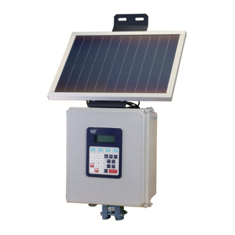
Mercos DMP 11 User manual

measuring and controling devices
DIGITAL PROCESS METER DMP 11
with accessories for analogue signals measuring
DMP 11
•
230 VAC or 24 V AC/DC power supply
• 6 digits LED 14,2mm display
• S ale -/+ 60 000
• Isolated analogue output (a tive and passive)
• Ex itation power supply upto 21,6V @ 130mA
• 2 or 4 relays output
• Optional CERTIFIED IP 65 en losure

Boleslavova 4, 709 00 Ostrava 9 tel / fax: +420 59 662 70 97
Created: 14.8.2019 , version 1.100en 2 email: mercos@mercos.cz
This device is designed for connection to hazardous electric voltages. Ignoring this warning can
result is severe personal injury or mechanical damage. To avoid the risk of electric shock and fire,
the safety instructions of this manual must be obeserved and the guidelines followed.
If the device is used in a manner not specified by the manufacturer, the protection provided by the
device may be impaired.
This device should be installed and adjusted by qualified electrical maintenance personnel familiar
with the connection and operation of the device and the hazards involved. Failure to observe this
precaution could result in injury.
ntil the device is fixed, do not connect hazardous voltages to the device - there is a risk of electric
shock.
Before putting the device into operation, this manual must be read carefully and familiarize yourself
with the features of the device and electrical wirrings.
The device is intended exclusively for industrial or professional use.
This device is subject to separate collection, do not dispose of it with municipal waste.
Jaroslav Rzepka MERCOS company is involved in the collective system ASEKOL a.s. (according
to the Waste Act). Company registration number at the Ministry of Environment is: 007 6105-ECZ.
Jaroslav Rzepka MERCOS company is involved in the associated performance EKO-KOM under
client number: EK-FO6050094.
The CE mark proves the compliance of the device with the essential requirements of the directives.
1. RECEIPT AND UNPACKING
Before putting the device into operation, please read this manual first and familiarize yourself with the features of the device and
wirrings. The device does not require any intervention and is capable of operation after unpacking. If the device has been stored
at too low or too high temperatures, it is necessary to let it acclimate for several minutes after unpacking.
. MOUNTING, ELECTRICAL WIRRINGS AND OPERATION
This device should be installed and adjusted by qualified electrical maintenance personnel familiar with the connection
and operation of the device, device setup can be done by instructed person.
In case of any doubts, do not hesitate to contact us at : 604 334 327 , mercos@mercos.cz
Make sure that proper power supply voltage is set and all input and outputs are connected correctly before connection to power
supply system – electrical wirrings diagrams are at the end of this manual.
This device is designed for is continuos run and doesn’t have own power-off switch. Installation must contains some power-off
switch or building distribution circuit-breaker (e.g. power-off switch in switchboard or main distribution circuit-breaker). It has to
be easy accessible by operating staff and has to be marked as cutting-off switch.
3. MAINTANANCE
DMP 11 is constructed to require minimal maintainance. Front panel with foil keypad isn’t resistant to organic solvents (e.g.
toluene, acetone etc...). Use only suitable non-agresive cleaners for cleaning front panel (e.g. industrial alcohol).
To prevent long-term failure-free operation, is recommned to use device in specified temperature range, not expose to extreme
climatic condition, which have effect to longtime lifecycle of electronic components.
4. REPAIR INSTRUCTIONS
Each device was subjected to components quality check control, pre-setting circuits and 24 hours burn-in on power supply. After
24 hours burn-in, pre-set parametres check was made. If device failure occurs (e.g. by overvoltage, mechanical damage, device
malfunction ... ), that impact its own functionality, it is necessary to contact manufacturer, which will provide appropriate repair.
5. WARRANTY
Manafacturer guarantees in accordance with §429 Commercial code (Czech Republic) for technical and operating
characteristics , specified in accompanying technical documentation. Device has 36 months warranty and after warranty service
is provided. This warranty does not apply: (a) to damage caused by accident, abuse, misuse, misapplication; (b) to unauthorized
repair or modification or (c) if serial number has been removed or defaced.

Boleslavova 4, 709 00 Ostrava 9 tel / fax: +420 59 662 70 97
Created: 14.8.2019 , version 1.100en 3 email: mercos@mercos.cz
How to control DMP 11
After power-on device shows measured value and device entered main display mode. In main display
mode we could switch between several values by pressing key (see the following table). Number of
available items in main display mode vary due to settings and configuration of device.
Measured value L1 limit L2 limit L3 limit L4 limit offset Tara / hold
- 2500 L1 L2 L3 L4 OFFSET tara
hoLd
By pressing key device shows value of selected item or executes its function (Tara/hold). By
pressing key again device enters in numeric input mode . By pressing key, we can go back one
step at a time without making any changes. If we press key, device stores edited value into
EEPROM and shows message hotovo.
0 glowing segment ; 0 flashing segment
L1 2000 002000 hotovo
Entering address menu
To access the address menu, press the keys and together. The device now requires a password.
A message E PASS is displayed if the password is incorrectly entered and in the device memory the
number of invalid attempts to enter the menu is increased by 1. The password is set to 1432 from the
manufacturer. The user can change this password.
0000 1000 1000 1100 A_00
Numeric input mode
When entering a numeric value, the first digit from the left will flash, by pressing key we will move
one by one digit to the right. To change the value of the current digit (flashing), press the key and
cycle through the value with each press one up (0 .. 1 .. 2 to 9 .. 0 .. 1 etc). In the first position on the
left, only 0 or a minus sign is valid. Press the key to stop editing the numeric value at any time.
002000 002000 012000 022000 hotovo
Numeric option mode
When entering a numeric option, the last digit will flash and help text will appear from the left. To
change the numeric option, press the key and cycle through the selection with each press one up (0
.. 1 .. 2 .. 3 to 9 .. 0 .. 1 etc.).
0-20c0 4-20c1 0-10c2 Pot c3 hotovo

Boleslavova 4, 709 00 Ostrava 9 tel / fax: +420 59 662 70 97
Created: 14.8.2019 , version 1.100en 4 email: mercos@mercos.cz
Decimal point mode
The numeral flashes together with the decimal point. To change the position of the decimal point,
press the button and change it one position to the right with each press.
000000. 000.000 0000.00 00000.0 hotovo
Address menu of DMP 11
The individual functions and settings of the device are accessible at so-called addresses for simplicity.
After entering the correct password, we enter the address menu, each address has its own number
and is displayed in the format A_00 , A_01 , A_02 etc. To move up in address menu, press
the key and to move down the key. To enter the selected address, press the key. To exit the
address and return to the address menu without changing the data, press the key.
If we change the numeric value or option at the given address, we are informed about the successful
writing to the EEPROM by a message hotovo. We confirm this message with the key and the
device returns to the address menu to the given address. To exit the address menu and return to the
main view, press the key.
After entering the menu, the device continues to measure at 4 measurements / sec. The
device returns to the main display for longer periods of inactivity. When you exit the menu, the
device remembers the pass ord for 1 minute, so you do not need to enter it hen you re-
enter menu. You delete the pass ord immediately from the temporary memory of the device by
key. When entering the menu again, the last selected address is displayed.
The number of available addresses in the address menu depends on the device configuration
and its equipment.
If the password is forgotten, the password can be temporari y reset to factory‘s defau t.
Turn off the device and turn on the device again with the keys and pressed. The
password is now set to 1432 for 10 minutes and the origina password can be viewed in
the menu or a new password can be set.
Warning messages
E Advc Device malfunction, contact manufacturer E -Inp Input signal is lower than 3,8 mA
E PASS Invalid password was entered E Inp Input signal is higher than 20,5 mA
hotovo Data were stored into EEPROM Ovt-rA
Displayed value is lower than -65535
E Lin L1 value out of preseted range Ovt ra Displayed value is higher than +65536
E dAta EEPROM data integrity error, contact the manufacturer for further instructions
Device keys description
key Main display mode function Address menu function Function in address
Switching displayed items Move up in addresses Numeric input change or
numeral digit on position change
Move down in addresses A selected digit shift to the right
Enter selected item Enter in to selected address Confirmation and saving into EEPROM
Return to measured value display Return to main display mode Escaping withou saving !

Boleslavova 4, 709 00 Ostrava 9 tel / fax: +420 59 662 70 97
Created: 14.8.2019 , version 1.100en 5 email: mercos@mercos.cz
List of addresses and description
Address*
[ fa tory preset ] des ription options
0 – without filtration
1 – 1,5 sec filter
2 – 2 sec filter
3 – 2,5 sec filter
4 – 4,5 sec filter
5 – 7 sec filter
6 – 10,5 sec filter
A_00
[ 0 ] Input signal filtering settings ****
7 – 20 sec filter
0 – 0 to 20 A
1 – 4 to 20 A
2 – 0 to 10 V
3 – potencio eter 0 to 100%
4 – user def. current input I
5 – user def. voltage input U
6 – low voltage +/- 585 V
A_01
[ 1 ] Input signal selection
7 – user def. potencio eter
A_02
[ 0.00 ] Starting point of the scale +/- 60000 digits
A_03
[ 200.00 ] End point of the scale +/- 60000 digits
A_05
[ XXXX. XX ]
De imal point
allowed positions are indicated, last position = dec. point off 00.0.0.0.0.
0 – 25% brightness
1 – 50% brightness
2 – 75% brightness
A_06
[ 2 ]
Display brightness
display brightnes is changed immidiatelly, setting is saved after
the key is pressed.
3 – 100% brightness
A_08
[ 0.00 ]
User input s ale start point
It is necessary to have a signal source representing the start point connected to
the input during settings
+/- 60000 digits
A_09
[ 20.00 ]
User input s ale end point
It is necessary to have a signal source representing the end point connected to
the input during settings
+/- 60000 digits

Boleslavova 4, 709 00 Ostrava 9 tel / fax: +420 59 662 70 97
Created: 14.8.2019 , version 1.100en 6 email: mercos@mercos.cz
0 – disabled (pass protected)
1 – enabled (no pass protect.)
A_14
[ 0 ]
L1 limit display in ain display ode
With options 1 and 2, settings the L1 limit value is not
password-protected, option 2 allows you to change the L1 limit
within preseted range at A_60 and A_61) 2 – enabled within preseted
range (A_60 & A_61)
A_15
[ 20.00 ] Li it L1 value +/- 60000 digits
A_16
[ 0.01 ] Li it L1 numeral hysteresis value 0 to 30000 digits
A_17
[ 0,5 ] Li it L1 time hysteresis value 0 to 299,9 se onds
0 – level ode inverse
1 – level ode direct
2 – window ode inverse
A_18
[ 0 ] Li it L1 ontrol settings
3 – window ode direct
0 – disabled (pass protected)
A_19
[ 0 ]
L2 limit display in ain display ode
With options 1 settings the L1 limit value is not pass-protected 1 – enabled (no pass protect.)
A_20
[ 40.00 ] Li it L2 value +/- 60000 digits
A_21
[ 0.01 ] Li it L2 numeral hysteresis value 0 to 30000 digits
A_22
[ 0.5 ] Li it L2 time hysteresis value 0 to 299,9 se onds
0 – level ode inverse
1 – level ode direct
2 – window ode inverse
A_23 Li it L2 ontrol settings
3 – window ode direct
0 – 0 to 20 A
1 – 4 to 20 A
2 – 0 to 10 V
3 – user output 0 to 20 A
4 – user output 4 to 20 A
A_24
[ 1 ]
Output signal type setting
Option 3, 4 and 5 allows you to assign a user-defined scale
range A_25 and A_26) to the selected analog output type
5 – user output 0 to 10 V
A_25
[ 0.00 ] User output signal s ale start point +/- 60000 digits
A_26
[ 200.00 ] User output s ale signal end point +/- 60000 digits
0 – disabled (pass protected)
A_44
[ 0 ]
L3 limit display in ain display ode
With options 1 settings the L1 limit value is not pass-protected 1 – enabled (no pass protect.)
A_45
[ 60.00 ] Li it L1 value +/- 60000 digits

Boleslavova 4, 709 00 Ostrava 9 tel / fax: +420 59 662 70 97
Created: 14.8.2019 , version 1.100en 7 email: mercos@mercos.cz
A_46
[ 0.01 ] Li it L3 numeral hysteresis value 0 to 30000 digits
A_47
[ 0.5 ] Li it L3 time hysteresis value 0 to 299,9 se onds
0 – level ode inverse
1 – level ode direct
2 – window ode inverse
A_48
[ 0 ] Li it L3 ontrol settings
3 – window ode direct
0 – disabled (pass protected)
A_49
[ 0 ]
L4 limit display in ain display ode
With options 1 settings the L1 limit value is not pass-protected 1 – enabled (no pass protect.)
A_50
[ 80.00 ] Li it L4 value +/- 60000 digits
A_51
[ 0.01 ] Li it L4 numeral hysteresis value 0 to 30000 digits
A_52
[ 0.5 ] Li it L4 time hysteresis value 0 to 299,9 se onds
0 – level ode inverse
1 – level ode direct
2 – window ode inverse
A_53
[ 0 ] Li it L4 ontrol settings
3 – window ode direct
A_60
[ 0.00 ] Preseted range for L1 li it – lower range +/- 60000 digits
A_61
[ 10.00 ] Preseted range for L1 li it – upper range +/- 60000 digits
0 – no reaction (undefined)
1 – relay closes
A_62
[ 0 ] Relays response to 4-20 A current loop fault **
2 – relay opens (nor ally open)
0 – no reaction (undefined))
1 – drop to 3.5 A
A_63
[ 0 ]
Output signal response to 4-20 A current loop fault
The output signal must be set to 4-20 mA
2 – rising to 21.5 A
0 – disabled (pass protected)
A_64
[ 0 ] S ale offset display in ain display ode
1 – enabled (no pass protect.)
A_65
[ 0.00 ]
S ale offset settings
The offset value is added to the measured value - the displayed data may be
distorted!
+/- 60000 digits
0 – function disabled
1 – TARA function
A_66
[ 0 ] Function of main display FNC and external input ***
2 – HOLD function

Boleslavova 4, 709 00 Ostrava 9 tel / fax: +420 59 662 70 97
Created: 14.8.2019 , version 1.100en 8 email: mercos@mercos.cz
A_67 Minimal measured value display
in csae of power-loss the value is lost. Value is cleared by pressing button +/- 60000 digits
A_68 Maximal measured value display
in csae of power-loss the value is lost. Value is cleared by pressing button +/- 60000 digits
A_69 TARA value display/reset
Tara value is displayed first, by pressing button we clear tara value
A_70 Input signal measuring – service ode
A_78 Nu ber of unsu essful attemps to enter device enu
Max number of attemps is 255, by pressing button we clear the value 0 to 255
A_79
[ 1432 ] Password hanging 0000 to 9999
Notice:
*) number of available menu addresses dependes on device configuration and accessories
**) Input current loop malfunction detection due to NAMUR NE43
***) External input is optional accessory, please check your device if it is available ( see device label )
****) Filtration is not active for potenciometers (selection 3 and 7 on A_01)

Boleslavova 4, 709 00 Ostrava 9 tel / fax: +420 59 662 70 97
Created: 14.8.2019 , version 1.100en 9 email: mercos@mercos.cz
Detail description of each address function
address
des ription
A_00
By settings higher ti e value filters could reach a stable easured value even in an
enviro ent with higher EMC levels.
The higher time value flter is set, the lower input signal response we get
A_01
Device works in two basic ways with input signal.
First one uses factory calibration to easure input signals - options 0, 1, 2, 3 and 5.
Second one let the user execute his own calibration to easure non-standart signal
ranges – option 4 and 6.
When option 4 or 6 is selected, input signal calibration has to be done on adresses A_08 and A_09.
A_02
Starting point of the scale assigned to the begining of input signal.
Example: Measuring water level in a tank input signal is 4-20mA , water level range is
0,500 to 4,000m ).
We set Starting point of the scale to value 000.500 and device assigns it to the input
signal of 4 mA.
A_03
End point of the scale assigned to the end of input signal.
Example: Measuring water level in a tank input signal is 4-20mA , water level range is
0,500 to 4,000m ).
We set End point of the scale to value 004.000 and device assigns it to the input signal of
20 mA.
A_05
Deci al point settings is global for all of these adresses – A_02, A_03, A_08, A_09, A_15,
A_16, A_20, A_21, A_25, A_26, A_45, A_46, A_50, A_51, A_60, A_61 and A_65.
Example: Measuring water level in a tank input signal is 4-20mA , water level range is
0,500 to 4,000m ).
We set decimal point to 000.000
A_06 Display brightness could be set in four levels. In low light enviro ents is di ed display
ore suitable.
A_08
User input scale start point requires connected input signal that corresponds to begining
of user input signal range.
Example: Distance measuring application input signal is 3,5 mA to 15,4mA , distance
0,200 to 11,000m )
1. We set user input scale start point to 000.200 and confirm it by pressing key.
2. Then connect corresponding input signal 3,5 mA to analogue input terminals, device
shows last measured data from A/D from previous calibration in1.3.2.7.6.. format.
3. In case we want to change scale value only and use previous calibration we press key
and finish user input scale start point settings.
4. If we want to make new calibration of input signal we repeatly press key, with each
press we get new measurement – so we could check input signal stability. Whenwe are
satisfied with measured A/D data we press key and finish user input scale start point
calibration and settings.
A_09
User input scale point requires connected input signal that corresponds to end of user
input signal range.
Example: Distance measuring application input signal is 3,5 mA to 15,4mA , distance
0,200 to 11,000m )
1. We set user input scale end point to 011.000 and confirm it by key

Boleslavova 4, 709 00 Ostrava 9 tel / fax: +420 59 662 70 97
Created: 14.8.2019 , version 1.100en 10 email: mercos@mercos.cz
2. Then connect corresponding input signal 15,4 mA to analogue input terminals and
follows instructions on A_08.
A_14
L1 limit display in main display mode offers direct access to L1 li it value settings. It has
three odes:
- option 0 : no direct access , L1 li it value is password protected
- option 1 : full access in ain display ode to L1 li it value
- option 2 : li ited access in ain display ode to L1 li it value – the range is li ited by
values set on addresses A_60 a A_61.
When option 2 is selected and user sets L1 limit value out of preseted range A_60, A_61) warning message
E Lin is displayed and value is corrected within preseted range and it is not saved.
A_15
L1 limit value can be set withing range of -60000 to +60000 digits, with respecting
deci al point settings.
Example: Water level measuring Scale 0,200 to 11,000m, L1 limit setpoint is 5.500m )
We set L1 limit value to 005.500 and confirm by key.
A_16
Limit L1 numeral hysteresis value (dL1) can be set within range 0 to 30000 digits, with
respecting deci al point settings.
Due to Li it L1 control settings (A_18) acts relay in these scenarios:
- Level mode (pict. 1) – dire t/inverse function (A_18,A_23,A_48,A_53)
- Relay loses/opens when easured signal rise over L1 + dL1 .
- Relay opens/ loses when easured signal drops bellow L1 – dL1 .
- Windows mode (pict. 2) – dire t/inverse function (A_18,A_23,A_48,A_53)
- Relay loses/opens when easured signals is within range defined by : ( L1 – dL1 ) < X <
( L1 + dL1 )
- Relay opens/ loses when easured signal is out of range defined by : ( L1 – dL1 ) < X < (
L1 + dL1 )
Example: Water level measuring Scale 0,200 to 11,000m, L1 limit setpoint is 5.500m )
We set L1 limit numeral hysteresis dL1 ) to 000.010 and confirm by key.
Pict. 1 Pict. 2
When selection 2 or 3 option window function– addresses A_14,23,48 and 53 )it is recommneded to set
time hysteresis dtLx to 0,5 seconds or more – to prevent fast relays closings/opens.
A_17
Limit L1 time hysteresis (dtL1) can be set in range 0.0 to 299.9 seconds.
When input signal rise over L1 + dL1 value or drop bellow L1 – dL1, device starts to count
down ti e hysteresis (dtL1) and then is relay opens/closes.
When input signal rise over L1 + dL1, dtL1 time hysteresis count down starts.If the input signal drops bellow
L1 + dL1 during count down, relay will not opens/closes and dtL1 time hystresis count down timer is reseted
When input signal drops bellow L1 – dL1, dtL1 time hystresis count down starts. If input signals rise over L1
– dL1 during count down, relay will not opens/closes and dtL1 time hysteresis count down timer is reseted.
A_18
Limit L1 ontrol settings defines relay behavior when li it L1 is reached
We can choose : direct/inverse level ode | direct / inverse window ode
see more at A_16 description
A_19 L2 limit display in main display mode offers direct access to L2 li it value settings.
opened
closed
5.500 5.510 5.490
opened
closed
5.500 5.510 5.490

Boleslavova 4, 709 00 Ostrava 9 tel / fax: +420 59 662 70 97
Created: 14.8.2019 , version 1.100en 11 email: mercos@mercos.cz
A_20
L2 limit value can be set withing range of -60000 to +60000 digits, with respecting
deci al point settings.
Example: Water level measuring Scale 0,200 to 11,000m, L2 limit setpoint is 6.500m )
We set L2 limit value to 006.500 and confirm by key.
A_21
Limit L2 numeral hysteresis value (dL2) can be set within range 0 to 30000 digits, with
respecting deci al point settings.
Due to Li it L2 control settings (A_23) relay acts as described on address A_16.
A_22
Limit L2 time hysteresis (dtL2) can be set in range 0.0 to 299.9 seconds.
When input signal rise over L2 + dL2 value or drop bellow L2 – dL2, device starts to count
down ti e hysteresis (dtL2) and then is relay opens/closes.
see more at address A_17
A_23
Limit L2 ontrol settings defines relay behavior when li it L2 is reached
We can choose : direct/inverse level ode | direct / inverse window ode
see more at A_16 description
A_24
Output signal type settings has two odes.
First mode (options 0,1 and 2) uses factory calibration where scale begin (A_02) is
assigned to begin of analog output signal and scale end (A_03) is assigned to end of
analog output signal
Se ond mode (options 3,4 and 5) offers possibility to assign user-defined scale to
analogue output signal (A_25 and a_26). Begin of analog output signal is assigned to A_25
value and end of analogue output signal is assigned to A_26.
A_25
User output signal s ale start point can be set withing range of -60000 to +60000 digits,
with respecting deci al point settings. This value represents begining of analogue output
signal.
Example: Water level measuring Scale 0,200 to 11,000m,output signal 4-20mA is
assigned for range 5.000 to 10.500m )
We set user output signal scale start point value to 005.000 and confirm it by key.
Analogue output signal will be 4mA when measured value will be 5.000.
All settings on this address are valid only for options 3,4 a 5 set on address A_24.
A_26
User output signal s ale start point can be set withing range of -60000 to +60000 digits,
with respecting deci al point settings. This value represents begining of analogue output
signal.
Example: Water level measuring Scale 0,200 to 11,000m,output signal 4-20mA is
assigned for range 5.000 to 10.500m )
We set user output signal scale start point value to 010.500 and confirm it by key.
Analogue output signal will be 20mA when measured value will be 10.500.
All settings on this address are valid only for options 3,4 a 5 set on address A_24.
A_44 L3 limit display in main display mode offers direct access to L3 li it value settings.
A_45
L3 limit value can be set withing range of -60000 to +60000 digits, with respecting
deci al point settings.
Example: Water level measuring Scale 0,200 to 11,000m, L3 limit setpoint is 7.500m )
We set L3 limit value to 007.500 and confirm by key.
A_46
Limit L3 numeral hysteresis value (dL3) can be set within range 0 to 30000 digits, with
respecting deci al point settings.
Due to Li it L3 control settings (A_48) relay acts as described on address A_16.

Boleslavova 4, 709 00 Ostrava 9 tel / fax: +420 59 662 70 97
Created: 14.8.2019 , version 1.100en 12 email: mercos@mercos.cz
A_47
Limit L3 time hysteresis (dtL3) can be set in range 0.0 to 299.9 seconds.
When ipnut signal rise over L3 + dL3 value or drop bellow L3 – dL3, device starts to count
down ti e hysteresis (dtL3) and then is relay opens/closes.
see more at address A_17
A_48
Limit L3 ontrol settings defines relay behavior when li it L3 is reached
We can choose : direct/inverse level ode | direct / inverse window ode
see more at A_16 description
A_49 L4 limit display in main display mode offers direct access to L4 li it value settings.
A_50
L4 limit value can be set withing range of -60000 to +60000 digits, with respecting
deci al point settings.
Example: Water level measuring Scale 0,200 to 11,000m, L4 limit setpoint is 8.500m )
We set L4 limit value to 00 .500 and confirm by key.
A_51
Limit L4 numeral hysteresis value (dL4) can be set within range 0 to 30000 digits, with
respecting deci al point settings.
Due to Li it L4 control settings (A_53) relay acts as described on address A_16.
A_52
Limit L4 time hysteresis (dtL4) can be set in range 0.0 to 299.9 seconds.
When ipnut signal rise over L4 + dL4 value or drop bellow L4 – dL4, device starts to count
down ti e hysteresis (dtL4) and then is relay opens/closes.
see more at address A_17
A_53
Limit L4 ontrol settings defines relay behavior when li it L4 is reached
We can choose : direct/inverse level ode | direct / inverse window ode
see more at A_16 description
A_60
Preseted range for L1 li it – lower range can be set withing range of -60000 to +60000
digits, with respecting deci al point settings.
When entering to the settings of li it L1 value fro ain display ode with option 2 set
on A_14 is the value of L1 li ited within preseted range (A_60, A_61). This feature is
useful to preset safe range when operating personnel needs to change li it L1 value.
A_61
Preseted range for L1 li it – upper range can be set withing range of -60000 to +60000
digits, with respecting deci al point settings.
When entering to the settings of li it L1 value fro ain display ode with option 2 set
on A_14 is the value of L1 li ited within preseted range (A_60, A_61). This feature is
useful to preset safe range when operating personnel needs to change li it L1 value.
When user set value out of preseted range, warning message E Lin is displayed and the value is
changed according preseted, but it is not saved.
A_62
Relays response to 4-20 A current loop fault provides user option to set defined
reaction of device relays when current loop fails.
Input signal type has to be set to 4-20 mA A_01, option 1
A_63
Output signal response to 4-20 A current loop fault provides user option to set defined
reaction of device AO when current loop fails.
Input signal type has to be set to 4-20 mA A_01, option 1) ) and output signal type to 4-20mA
A_24, option 1)
A_64 S ale offset display in ain display ode provides user option to direct access of offset
value settings fro ain display ode
A_65
S ale offset settings can be set withing range of -60000 to +60000 digits, with respecting
deci al point settings. Offset value is added to easured value, so the displayed value is
corrected. To switch off offset function, set zero value on this address.
The offset value is added to the measured value - the displayed data may be distorted!

Boleslavova 4, 709 00 Ostrava 9 tel / fax: +420 59 662 70 97
Created: 14.8.2019 , version 1.100en 13 email: mercos@mercos.cz
A_66
Function of main display FNC and external input
TARA – by executing tara function is easured value zeroed
HOLD – device will hold displayed value for 20 seconds, easuring is not affected
External input is optional accessory and settings works for both.
Active HOLD function is sy bolized by blinking 1st left deci al point 0.0 .500
A_67
Minimal measured value display stores lowest easured value fro last power on, to
reset value press key and select Ano.
Value is reseted with powerloss
A_68
Maximal measured value display stores highest easured value fro last power on, to
reset value press key and select Ano.
Value is reseted with powerloss
A_69
TARA value display/reset offers user both preview of actuall tara value and tara value
reset option. To reset tara value press key and select Ano.
Value is saved if powerloss occured
A_70
Input signal measuring – service ode
Value on this address shows actual input signal easured physical value due to options
on the adress A_01 in respective physical units ( A, V, V).
Device is in special measuring mode here and stops converting signal, control relays, AO and etc.
A_78
Nu ber of unsu essful attemps to enter device enu is increased by 1 with each wrong
password. This address offers preview of total atte ps and reset option. To reset
nu bers of atte ps press key and select Ano.
Max number of attemps is 255
A_79
Password hanging address offers user to set his own password. Factory set password
provides basic level of security. Password can be set in range 0000 to 9999 .
In case of password lost, follow instructions at section „address menu of DMP11“

Digital process meter DMP 11 provides physical value measuring with
displaying it within -60000 to +60000 digits range. Internal analogue
sigma-delta converter offers resolution of one digit even in full scale
range. Device provides adjustable input signal scale, output signal
scale, decimal point and etc. to fit any kind of application. ser can even
set his own calibration for current, voltage (low, high) and potencimeters
signals. Potencimeter measuring is based on the ratio measurement,
slow changes in total potentiometer resistance do not affect
measurement accuracy. Device has implemented NAM R NE43 input
current loop 4-20mA checking, with defined behaviour in case of current
loop error.
FUNCTIONS
DISPLAYS measured physical value
INPUT SIGNAL SELECTION by user
SCALE RANGE upto -60000 to +60000 digits
EXCITATION POWER SUPPLY included
4 RELAYS FUNCTION
direct / inverse level mode – relays closes / opens when limit is
reached
direct window mode – relays closes in range defned by numeral
hysteresis and limit value
inverse window mode – relays closes when signal is out of range
defined by numeral hysteresis and limit value
NUMERAL HYSTERESIS for each limit
TIME HYSTERESIS for each limit
ANALOGUE OUTPUT fully adjustable by user
0 / 4 – 20 mA DC, 0 – 10 V DC
inverse AO : 20 – 4 / 0 mA , 10 – 0 V DC
fully adjustable eg. 12-18 mA , 1,6 – 8,3 V
TARA and HOLD FUNCTION as standart equipment
DIGITAL INPUT for TARA and HOLD function (optional acc.)
INPUT 4- 0 mA CURRENT LOOP CHECK
comply to NAM R NE43 *
defined relays and analogue output behavior
DISPLAY BRIGHTNESS in 4 levels
LIMIT L1 VALUE RANGE RESTRICTION for operating
personnel
DIGITAL FILTERS for measured signal
GALVANIC INSULATION
Power supply from: input, output, excitation power supply & relays
input signal from output signal
relays output betweeneach other
*) valid signal is within range 3,8 mA to 20,5 mA
**) 130mA excitation power supply is an optional accessory
***) DMP11-10010 version only
****) DMP11
-
22121 version has max. operating temp 45°C
DIGIT
AL PROCESS MET
ER DMP 11
30 V or 4 V power supply for current and voltage signals
TECHNICAL DATA
DISPLAY -60 000 to +60 000 – red LED 14,2 mm
PW R.S PPLY 230V 230 VAC (-20% / +15%)
24 VAC or 24 VDC (-15% / +20%)
21,6 to 52,8 VDC – with all accessories
POWER S PPLY
24V
10,6 VDC to 52,8 VDC – without accessories ***
2,5 W – without accessories
+ 0,7 W – 2 relays
+ 1,4 W – 4 relays
+ 0,7 W – isolated analogue output
CONS PTION
Device has
T500mA fuse
+ 1,0 W / 3.0 W – excitation power supply
Exc. power supply 21,6V @ 30mA or 21,6V @ 130mA **
current input – 50Ω + 13 Ω PTC
voltage input 10 V – 370kΩ
INP T
RESITANCE
voltage input 295 mV – greater than 10 MΩ
POTENCIOMETER 3-wires connection (input resistance greater than 1MΩ)
SAMPLES 16,7 meas/sec (internal) ; 4 samples/sec – (display)
DIG.RESOL TION analogue input – 20 bits / analogue output – 14 bits
RESPONSE TIME 10% to 90% – input / output : 180 ms (w/out filters)
ACC RACY +/- 0,1 % from full range +/- 2digits
TEMP.COEFFIC. 0,005 % from full range / °C @ Tref = 23°C
ISOLATION
STRENGTH - 30 V
3 kV po er supply vs.input/output/relay
1 kV input vs.output. vs. digital input
ISOLATION
STRENGTH - 4 V
1,5 kV po er supply vs.input/output/relay
1 kV input vs.output. vs. digital input
ANALOG.O TP T max. 21,5 mA or max. 10,5 V DC
O TP T IMPEDANCE current : max. 600 PQvoltage/AP
&-R) 3
)D'%=)-2
/( short-circuit resistant )
/( short-circuit resistant )
%'=-I*) 3 5659?D-(LA-
=&*=40=6 +B>":????.
0?9????
=&*=40=6
EI*'%'** 0??5888
0>
=&*=40=6
=)N( <()< 0>
2&'<*)<* 8:!6@!@A+!!.0cutout 91 x 44 mm +!.
'<(=)* %' 36?
,%%<N()<<'()< max. conductor cross-section is 2,5mm
,'NE 5K?0with all accessories
*-#=*-)< A
)3'%-<N'&3 "5AH(BA?H(FFFF
*)%-N''&3 "6?H(B@AH(
E &2I 5?JSES@?J+.
)3'%-)<
*'-= 2' !5???
-33=(-)< intended solely for industrial or professional use
'&( T*<'<:495:"45/5?49
'&( T*<'<AA?449/5?4?B-4/5?44#4
'='(%(-=*-'I T*<'<:4?4?"45/5?44T*<'<:4?4?"5"?9?/5?44
'&(!B>"?4J
OPTIONAL ACCESSORIES
or 4 releays outputs
30 VAC @ 5A
=4=5=9=6Independent. set
Isolated analogue output
0 – 0 mA DC
4 – 0 mA DC
( %%'<
active / passive
D)=-N' 0 – 10 V DC
Excitation power supply
upto 1,6 VDC @ 130mA +/- 10%
INTRODUCTION
INPUT SIGNALS
Preset
0 – 0 mA DC
( %%'< 4 – 0 mA DC
D)=-N' 0 – 10 V DC
3)'<()&''% 0 – 100 %
Adjustable by user
( %%'< - 4 – 1 mA DC
+/- 0 – 10,5 V DC
D)=-N' +/- 0 – 95 mV DC
3)'<()&''%100 Ω – .0 kΩ

ORDER CODE
DMP 11 -
. . . . .
A B C D E
TERMINAL STRIP
4056D-(>D2("4AB5?J
A
Power
supply 5059?D-("5?B4AJ
?0>
405
B
Relay
output
506
?0>
C
Analogue
output 40
40!54:D2(L30 mA
D
Excitation
power
supply 50!54:D2(L130 mA
?0>
E
Digital input
40
ORDER EXAMPLE
DMP 11
–
11
10
" 59?D-(
" 5
"
" !9?-
" >
LEGEND:
1, 2, 3, 4, 16 a 17 G!+-B3<.
5 - 10, 18 23
A:K %4+=4.
@84? %5+=5.
4@485? %9+=9.
545559 %6+=6.
14 i , 15 i, 14 u, 15 u +-).
24, 25 +2.
COM, +A a -B %*6@A
L, N 30V AC
I, II 4V DC / 4V AC
OUTPUT SIGNALS WIRRINGS for DMP 11
CURRENT OUTPUT
?>605?-
2&344
605?-
2&344
?04?D2(
2&344
O
VOLTAGE OUTPUT
"
46
4A
%
U
!:??M
BI)
"
46
46
%U
!4ML56D2(
BI)
O
4?
"
5:D2(
B
"
4A
46
%
U
AM
B
U)
BACK PANEL VIEW
–
230 V
4@
48
5?
54
55
59
4A
46
46
4A
A
:
K
@
8
4?
<
=
4 5
9
6
4:
4K
()&
"-
B#
56
5A
INPUT SIGNALS WIRRINGS for DMP 11
CURRENT INPUT
-(D'*'<*
?>605?-
B>"?05?-
?>605?-
2&344
3-**D'*'<*
605?-
2&344
605?-
!
4 5 4K
*'<*)%* 33=I
B56D
2(
()&
BI<
B
"
5
4K
*'<*)%* 33=I
B56D
2(
BI<
B
"
()&
4 5
BI<
B
"
4 5
()&
BI<
B
"
B
"
VOLTAGE INPUT
?04?D2(
B>"?04?D2(
?04?D2(
2&344
O
()&
BU<
4 4:
B
"
O
()&
BU<
4 4:
4K
B
"
*'<*)%* 33=I
B56D
2(
O
BU<
5 9
B
"
?058AD2(
B>"58AD2(
POTENCIOMETER
+.
4?P0A??P
2&344
()&
5 9
6
B
"
U
"U<
DIGITAL INPUT
56D2(
56
5A
ISOLATION DIAGRAM
–
230 V
<
=
59?D
-(
-)
2
-
%4
%5
%9
%6
9D
4D
4D
"
B
4
5
9
6
4
:
4
K
A
:
K
@
8
4
?
<
=
4@
48
5?
54
55
59
56
5A
4A
46
46
4A
()&
B-
"#
-B3<
%4
%5
%9
%6
"
B
-)
B
"
-)
3
59?D
-(
%*6@A
"
B
2
2
3
56D-(
56D2(
Power
s
upply is
not universal –
please specify
power supply in
order code

Boleslavova 989/4
Ostrava 9, 709 00
Czech Republic
/B65?A8::5K?8K
&/B65?:?5@????K
'/L
,//>>
Verze: 1.100en / 14.8.2019
Table of contents
