VMI Viber X Series User manual

VIBER X1™ Manual
VIBER X1™ Manual
Ver. 1.0
VIBER X
™

Our X series of hand-held instrument
VIBER X1 VIBER X2 VIBER X3
VIBER X5
Our X series of hand-held instruments
Our X series of hand-held instrument
VIBER X1 VIBER X2 VIBER X3
VIBER X5
Important information
Safety precautions
Vibration measurement and balancing involves measurement on rotating machines.
Keep a safe distance to rotating parts and secure transducers and transducer cables
from rotating parts. Always follow internal, local and national security
regulations! When working with weights on the rotor always secure the start
switch with a locker and also use the emergency switch for double safety. This is
especially important when the machine is remote controlled.
VMI International AB takes no responsibility for any accidents on people and
machines.
VMI International AB and our authorized dealers will take no
responsibility for damages on machines and plants as the result
of the use of VIBER X1™ measurements.
Even though great efforts are made to make the information in
this manual free from errors and to make the information
complete for the user, there could be items we have missed,
because of the large amount of information. As a result of this,
we might change and correct these items in later issues without
further notice. Also changes in the VIBER X1™ equipment may
take place that affect the accuracy of the information.
VIBER X1 VIBER X2 VIBER X3
VIBER X5 MKIII

3
Important information
Safety precautions
Vibration measurement and balancing involves measurement on rotating machines.
Keep a safe distance to rotating parts and secure transducers and transducer cables
from rotating parts. Always follow internal, local and national security
regulations! When working with weights on the rotor always secure the start
switch with a locker and also use the emergency switch for double safety. This is
especially important when the machine is remote controlled.
VMI International AB takes no responsibility for any accidents on people and
machines.
VMI International AB and our authorized dealers will take no
responsibility for damages on machines and plants as the result
of the use of VIBER X1™ measurements.
Even though great efforts are made to make the information in
this manual free from errors and to make the information
complete for the user, there could be items we have missed,
because of the large amount of information. As a result of this,
we might change and correct these items in later issues without
further notice. Also changes in the VIBER X1™ equipment may
take place that affect the accuracy of the information.
Important information
Safety precautions
Vibration measurement and balancing involves measurement on rotating
machines. Keep a safe distance from rotating parts. Secure transducers
and cables from rotating parts. Always follow company, local and national
security regulations!
VMI International AB and our authorized dealers will take no
responsibility for either damages on machines and plants or accidents on
people as the result of the use of VIBER X
™measurements.
Even though great efforts are made to make the information in
this manual free from errors and to make the information complete for the
user, there could be items we have missed, because of the large amount of
information. As a result of this, we might change and correct these items
in later issues without further notice. Also changes in the VIBER X™
equipment may take place that affect the accuracy of this information.

4
Instrument overview
The VIBER X1™ is a portable Vibrometer to be used in preven-
tive and active maintenance work, especially on rotating machin-
ery.
A complete set consist of an instrument, carrying bag, a vibration
transducer with magnet support and charger.
VIBER X1™ is measuring the effective velocity (mm/s RMS)
in the frequency range 2 – maximum frequence. The range can be
set by adjustable filters, high pass filters can be set 2 Hz or 10 Hz,
low pass filters can be set at 1 000 Hz or maximum frequency.
This range covers most of the frequencies that will occur for the
majority of mechanical failures and imperfections. Examples are
unbalance, looseness, resonance, misalignment of shafts and gears,
cavitations and other fluid generated vibrations.
The judgements of the measured levels are supported by several
vibration standards. The close comparison between vibration
levels and actual wear of the machinery will build up local
knowledge. This experience should be used to optimise the type of
action required when higher vibrations are found.
A common standard for judgement of vibrations is ISO 10816-3
and may be available from domestic standardisation authority.
This standard is an upgrade of older standards that has been in use
for several decades and has a worldwide acceptance as a
good judgement for continuous and long lasting operation of
machinery.
Instrument overview
The VIBER X
™is a portable vibrometer to be used in
preventive and pro-active maintenance work, especially on
rotating machinery. A complete set consists of an instrument,
soft carrying bag, a vibration transducer with magnet support.
VIBER X™ measures the velocity (mm/s RMS) in the two
frequency ranges 10 - 1000 Hz or 2 Hz – maximum frequency
(16000 Hz depending on version of VIBER X™ and trans-
ducer). The instrument has the capability to measure up to 40
kHz, the limiting factor is the accelerometer.
This range covers most of the frequencies that will occur for
the majority of mechanical failures and defects. Examples
are unbalance, looseness, resonance, misalignment of shafts,
vibrations.
VIBER X™ 10 - 1000 Hz is designed for companies that
uses the recommendation ISO 10816-3. This standard, is used
for decades around the world.
The vibration alerts are supported by several vibration stan-
dards. The close comparison between vibration levels and
actual machinery wear will build up your knowledge. Use
this experience to determine the action required when high
vibrations are found.

5
Vibraon Measurement Instruments
Functions
Press the start key and the instrument starts to measure
vibration, default is 2 – maximum frequency range, the diodes
indicates low and high pass fi lters setting.
The instrument will be shut off automatically after approximately
4 minutes if no key are used during the time.
This button can be used if the digits need a higher brightness to be
more visible.
The Viber X1™ is one of few analogical instrument that has
adjustable frequency ranges. To measure in other frequency
range, use the up/down arrows to change the fi lters. The fi lters
LED will light up to show the fi lter in use. This can be a useful
feature; comparison can be done with measurements in the
same range. Notice that the old ISO standard had 10 -1000 Hz
as frequency range. We recommend you to use 2 – 1000 Hz
as a standard range.
Start of the instrument
Improving the light
Changing frequency range
Manual Viber X1_121002.indd 5 10/3/12 9:26 AM
Power on the instrument
Press the On/Off key and the instrument starts to measure
vibration, default is 10 - 1000 Hz or 2 Hz – maximum
frequency range depending on version. The instrument shuts
off automatically after approximately 4 minutes if no key is
pressed.
Vibraon Measurement Instruments
Battery check
VIBER X1™ has an embedded battery check, when less than 10 %
of the battery capacity remains, the battery LED will fl ash.
Press this symbol key and the measurement of bearing condition
will start. The instrument measures instantaneously a bearing
condition value in the range between 500 Hz to 20.000 Hz.
To go back to vibration measurements, press the symbol once
more.
Placing of the measuring point
The measurements should be taken on or as close to the bearing as
possible and in horizontal, vertical and axial directions.
Bearing condition
Manual Viber X1_121002.indd 6 10/3/12 9:26 AM
Start measuring vibration on the machine then, press the
symbol key for bearing condition measurement. The instru-
ment measures instantaneously a Bearing Condition value in
the range between 500 Hz to 16 000 Hz. To return to vibration
measurement, press the symbol again.
Vibraon Measurement Instruments
Functions
Press the start key and the instrument starts to measure
vibration, default is 2 – maximum frequency range, the diodes
indicates low and high pass fi lters setting.
The instrument will be shut off automatically after approximately
4 minutes if no key are used during the time.
This button can be used if the digits need a higher brightness to be
more visible.
The Viber X1™ is one of few analogical instrument that has
adjustable frequency ranges. To measure in other frequency
range, use the up/down arrows to change the fi lters. The fi lters
LED will light up to show the fi lter in use. This can be a useful
feature; comparison can be done with measurements in the
same range. Notice that the old ISO standard had 10 -1000 Hz
as frequency range. We recommend you to use 2 – 1000 Hz
as a standard range.
Start of the instrument
Improving the light
Changing frequency range
Manual Viber X1_121002.indd 5 10/3/12 9:26 AM
Vibraon Measurement Instruments
Battery check
VIBER X1™ has an embedded battery check, when less than 10 %
of the battery capacity remains, the battery LED will fl ash.
Press this symbol key and the measurement of bearing condition
will start. The instrument measures instantaneously a bearing
condition value in the range between 500 Hz to 20.000 Hz.
To go back to vibration measurements, press the symbol once
more.
Placing of the measuring point
The measurements should be taken on or as close to the bearing as
possible and in horizontal, vertical and axial directions.
Bearing condition
Manual Viber X1_121002.indd 6 10/3/12 9:26 AM
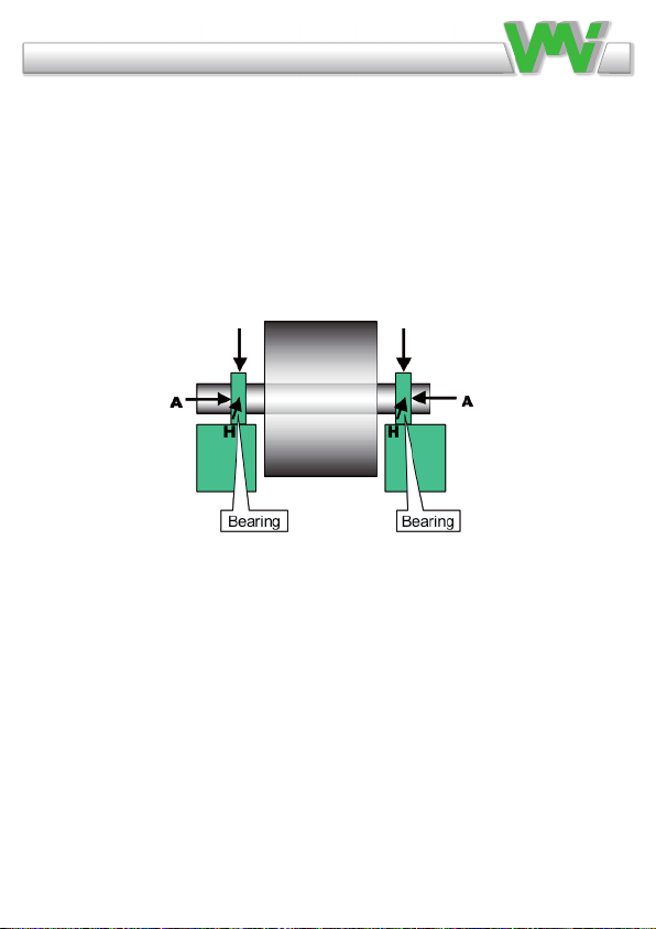
Measuring point location
Measurements should be taken on the bearing housing or as
close as possible and in the horizontal, vertical and axial direc-
tions. This is also explained in the standard ISO-10816.
6
V V
Vibraon Measurement Instruments
Functions
Press the start key and the instrument starts to measure
vibration, default is 2 – maximum frequency range, the diodes
indicates low and high pass fi lters setting.
The instrument will be shut off automatically after approximately
4 minutes if no key are used during the time.
This button can be used if the digits need a higher brightness to be
more visible.
The Viber X1™ is one of few analogical instrument that has
adjustable frequency ranges. To measure in other frequency
range, use the up/down arrows to change the fi lters. The fi lters
LED will light up to show the fi lter in use. This can be a useful
feature; comparison can be done with measurements in the
same range. Notice that the old ISO standard had 10 -1000 Hz
as frequency range. We recommend you to use 2 – 1000 Hz
as a standard range.
Start of the instrument
Improving the light
Changing frequency range
Manual Viber X1_121002.indd 5 10/3/12 9:26 AM

7
Vibraon Measurement Instruments
How to make good measurements
The sensitivity direction of the transducer coincides with the
centre axis of the transducer. The transducer end (with the
magnetic support) is pushed fi rmly against the measurement
point. The main purpose is to make the complete transducer to
fully participate in the motion of the measurement point. Try to
hold the transducer in a vertical, horizontal or axial direction as
possible, even if the machine surface does not have these
directions. Read the instrument held with the free hand. Note a
stable reading as well as a fl uctuating one, since the fl uctuation
itself is valuable information regarding the reason for the
vibration.
When the transducer is mounted with the magnet the frequency
range of the measurement is reduced to about 2 000 - 3 000Hz
depending on the fl atness of the measuring surface.
Note!
When using the magnet the bearing condition value can be
substantially changed.
Vibrations at high frequencies can sometimes cause measurement
lack of confi dence. Pressing the transducer more fi rmly should
not change the reading. If in doubt, always try to adjust the
contact point fi rst. Secondly, if necessary, mount the transducer
with the M6 stud.
All normal measurements on vertical or horizontal machinery
should follow the three perpendicular axes of true vertical,
Manual Viber X1_121002.indd 7 10/3/12 9:26 AM
How to make good measurements
The sensitivity direction of the transducer coincides with the
center axis of the transducer. Place the accelerometer on the
measurement point. Wait a few seconds for the accelerometer
to come to a steady state to reduce noise from the accelero-
meter. If you are connecting to a non-magnetic surface, push
rmly against the measurement point. Make sure it is a proper
contact with the machine. If measurement are taken on a
curved surface, make sure the accelerometer is attached and
not moving back and forth. Measure a vertical, horizontal and
axial direction, if possible. Note if the reading is stable or uc-
tuating. The non-stable reading is also valuable information
used to determine the vibration cause.
When the transducer is mounted with the magnet, the reliable
frequency range of the measurement is reduced to about 2000
– 3000 Hz depending on the atness of the contact between
magnet and surface.
Note!
Using the magnet can change the bearing condition value.
High frequency vibration can sometimes be difcult to collect
because high vibration does not transmit through the machine
for long distances. Pressing the transducer more rmly should
not change the reading. If in doubt, always try to adjust the
contact point rst. Secondly, if necessary, mount the transdu-
cer with the M6 stud.

8
horizontal and axial directions. The reason is that you should keep
to the main stiffness directions caused by normal non symmetrical
properties of the foundation, piping, supports etc. It will result in
better understanding if the basic measurements are made in this
way.
The VIBER X1™ is mainly intended for measurements against
the housing and bearings of machinery according to the intentions
of the standards. You can also use it to measure other parts such
as piping, valves, etc. Note that in some cases the mass of the
transducer may influence the reading. A good rule is to consider
readings on surfaces that are lower in mass than 10 times the mass
of the transducer.
All normal measurements on vertical or horizontal machinery
should follow the three perpendicular axes of true vertical,
horizontal and axial directions.
The VIBER X
™is mainly intended for measurements
against the machinery housing and bearings. And designed for
fans, pumps, chemical motors and compressors.
VIBER X
™can also be used to measure other components
such as piping, valves, etc.
Note
the reading. A good rule is to avoid readings on things that
have only 2-3 times the mass of the transducer.

9
How to interpret vibration measurements
A user with no previous experience to interpret the results is
recommended to use the ISO 10816-3 standard.
The standard normally calls for a measure in velocity based on
mm/s RMS. To better understand what this measure means it can
be helpful to consider the reading as a mean value of the back and
forward motion. This measure gives a good understanding of the
amount of “break down energy”, causing mainly wear and fatigue
work, in the machine or the structure being measured.
The instrument is measuring the total RMS-value of the vibration
in actual frequency range. This RMS-value is an average sum of
all the measured vibrations.
Example:
If the simultaneous vibration caused by unbalance is (4mm/s), by
misalignment (2 mm/s) and by the gear mesh (5 mm/s) then the
total vibration measured with VIBER X1™ is 6.7 mm/s.
Total vibration =
Notice that a reduction of the unbalance from 4 mm/s to 1 mm/s
will reduce the total value from 6, 7 mm/s to 5, 5 mm/s.
√4 * 4 + 2 * 2 + 5 * 5 = 6.7mm
How to interpret vibration measurements
A user with no previous experience, we recommend to use the
ISO 10816-3 standard.
The standard normally calls for a velocity measurement in
mm/s RMS. To better understand what this measurement
means, think of it as how fast the machine is
moving back and forth. This measure gives a good understan-
ding of the amount of “break down energy”, causing mainly
wear and fatigue in the machine or the structure.
The instrument measures the total RMS vibration value in the
frequency range. This RMS value is the average sum of all the
measured vibrations.
Example:
If the simultaneous vibration caused by unbalance is (4mm/s),
by misalignment (2 mm/s) and by the gear mesh (5 mm/s)
then the total vibration measured with VIBER X™ is 6.7
mm/s.
Total vibration = √4 * 4 + 2 * 2 + 5 * 5 = 6.7mm
Notice that a reduction of the unbalance from 4 mm/s to 1
mm/s will reduce the total value from 6, 7 mm/s to 5, 5 mm/s.

10
Vibraon Measurement Instruments
The ISO standard is classifying the machines differently if the
machines are considered as fl exible or rigid mounted. This refl ects
the location of the machines stiff-body resonance’s related to the
basic running speed of the machine.
For instance, a machine supported by rubber or springs have
resonance’s at low running speeds. The machine starts vibrate
at certain low rpm. When the speed is increased above these
resonance frequencies the vibration is reduced. This machine is
considered fl exible.
A resonance can easily be found when a fl exible machine is
running up or down in speed. The resonances are located at
the rpm´s where the vibration has a local maximum level.
Manual Viber X1_121002.indd 10 10/3/12 9:26 AM
The ISO standard classies the machines differently if the machi-
nes are exible or rigid. This reects the location of the machine’s
stiff-body resonance related to the basic running speed of the
machine.
For example, a machine supported by rubber or springs have a
resonance at low running speeds. The machine starts vibrate at
a low RPM. When the speed is increased above these resonance
frequencies, the vibration is reduced. This machine is considered
exible.
Resonance is easily found when a exible machine is running up
or down in speed. The resonances are located at the speed where
the vibration has a local maximum level.
Rigid
1.4
mm/s
2.8
4.5
11
Group 2 and 1 Group 4 and 3
Rigid Flex. Flex. mm/
s
2.3
3.5
7.1
Extraction’s from ISO 10816-3
Industrial machines with power above 15kW and nominal
speeds between 120 - 15000 RPM.
Group 1:
Large machines with rated power
above 300kW. Electrical machines
with shaft height H > 315mm.
Operating speed ranges from 120 to
15000 RPM.
Group 2:
Medium-sized machines with a rated power above 15kW up to and
including 300kW. Electrical machines with shaft height between
160 < H < 315 mm. Operating speed normally above 600 RPM.

11
Vibraon Measurement Instruments
Modern machines often run at high speed and bearing-supports
are fl exible, foundations should/can be evaluated as fl exible, even
when it is not mounted on rubber or springs.
The ISO 10816-3 standard allows for slightly higher limits when
a foundation is considered fl exible than when if it is rigid.
A conclusion from this is also that a resonance condition in
principle is not allowed or at least must be avoided at operating
speeds. In practice this also includes the double speed as well as
any other natural excitation frequency such as blade passage etc.
A great advantage with proper vibration measurements and the
use of vibration standards is that you can judge the future
maintenance cost reliably already at fi rst start-up. If you fi nd
levels above 3 mm/s RMS, you can be rather sure that the machine
will cause increased activities in maintenance.
The specifi c cost and action is of course individual to the
machine design.
The next logical step is therefore to apply more advanced
analyzers like VIBER X2™, X3™ or X5™ to learn the frequency
behind the vibration and thus the exact mechanical fault.
The practice of this is beyond the scope of this manual.
Manual Viber X1_121002.indd 11 10/3/12 9:26 AM
Group 3:
Pumps with multivane impeller and with separate driver with
rated power above 15kW.
Group 4:
Pumps with multivane impeller and with integrated driver
with rated power above 15kW.
Modern machines often run at high speed and bearing-
supports are exible, foundations should/can be evaluated as
exible, even when it is not mounted on rubber or springs.
The ISO 10816-3 standard allows for slightly higher limits
when a foundation is considered exible than rigid. A conclu-
sion from this is a resonance condition should not be allowed
or at least must be avoided at operating speeds. In practice,
this also includes the double speed as well as any other natural
excitation frequency such as blade passage.
A great advantage with proper vibration measurements and
the use of vibration standards is that you can judge the future
maintenance cost reliably at start-up. If you nd levels above
3 mm/s RMS, it’s a risk that the machine will have higher
maintenance cost. The specic cost and action is specic to
the machine design.
The next logical step if you want to improve the accuracy of
measurements is to use more advanced analyzers like VIBER
X2™, X3™ or X5™ to learn and detect the frequency behind
the vibration and thus the exact mechanical fault. The practice
of this is beyond the scope of this manual.

12
Vibraon Measurement Instruments
Recommended vibration levels in mm/s and
common fi ndings
The following is in part an extraction of the old standard ISO 2372
class 4, large machines on fl exible foundations, with some com-
mon fi ndings added.
This simplifi ed list can be used, as a fi rst indication, when
approaching a machine newly commissioned or after some
time in operation.
Take as a rule to investigate the reason for any machine that vi-
brates above 3 mm/s RMS.
• 0 – 3 mm/s
Small vibrations - None or very small bearing wear. Rather low
noise level.
• 3 – 7 mm/s
Noticeable vibration levels often concentrated to some specifi c
part as well as direction of the machine. Visible bearing wear.
Seal problems occur in pumps and increased noise level. Keep
the machine under observation and measure at smaller time inter-
vals than before to detect a deterioration trend if any.
Compare vibrations to other operating variables.
Manual Viber X1_121002.indd 12 10/3/12 9:26 AM
Recommended vibration levels in mm/s and common ndings
The following is an extraction of part of the old standard ISO
2372 class 4, large machines on exible foundations, with
some common ndings added.
Use this simplied list as a rst indication, when approaching
a newly commissioned machine or after some time in opera-
tion. Investigate the reason for any machine that vibrates
above 3 mm/s RMS.
• 0 – 3 mm/s
Small vibrations - None or very small bearing wear. Rather
lownoise level.
• 3 – 7 mm/s
Noticeable vibration levels are often concentrated to some
specic part as well as direction of the machine. Visible
bearing wear. Seal problems occur in pumps and increased
noise level. Keep the machine under observation and measure
at smaller time intervals than before to detect a deterioration
trend if any. Compare vibrations to other operating variables.
• 7 – 18 mm/s
Large vibrations. Bearings running hot. Bearing wear-out
causes frequent replacements. Seals wear out, leakage of all
kinds evident. Cracks in welding and concrete foundations.
Screws and bolts are loosening. High noise level. Plan action
soonest. Do your best to discover the cause. You are wearing
down investments quickly.
13
Vibraon Measurement Instruments
• 7 – 18 mm/s
Large vibrations. Bearings running hot. Bearing wear-out cause
frequent replacements. Seals wear out, leakage of all kinds evident.
Cracks in welding and concrete foundations. Screws and bolts are
loosening. High noise level. Plan action soonest. Do your best to
reveal the reason. You are wearing down investments quickly.
• 18 – mm/s
Very large vibrations and high noise levels. This is detrimental to
the safe operation of the machine. Stop operation if technically
or economically possible considering the plant stop cost. Few
machines can withstand this level without damage. Reduce any
further running time to an absolute minimum.
Manual Viber X1_121002.indd 13 10/3/12 9:26 AM
Vibraon Measurement Instruments
Recommended vibration levels in mm/s and
common fi ndings
The following is in part an extraction of the old standard ISO 2372
class 4, large machines on fl exible foundations, with some com-
mon fi ndings added.
This simplifi ed list can be used, as a fi rst indication, when
approaching a machine newly commissioned or after some
time in operation.
Take as a rule to investigate the reason for any machine that vi-
brates above 3 mm/s RMS.
• 0 – 3 mm/s
Small vibrations - None or very small bearing wear. Rather low
noise level.
• 3 – 7 mm/s
Noticeable vibration levels often concentrated to some specifi c
part as well as direction of the machine. Visible bearing wear.
Seal problems occur in pumps and increased noise level. Keep
the machine under observation and measure at smaller time inter-
vals than before to detect a deterioration trend if any.
Compare vibrations to other operating variables.
Manual Viber X1_121002.indd 12 10/3/12 9:26 AM
• 18 – mm/s
Very large vibrations and high noise levels. This is detrimental
to the safe operation of the machine. Stop operation if techni-
cally or economically possible. Few machines can withstand
this level without damage. Reduce any further running time to
an absolute minimum.
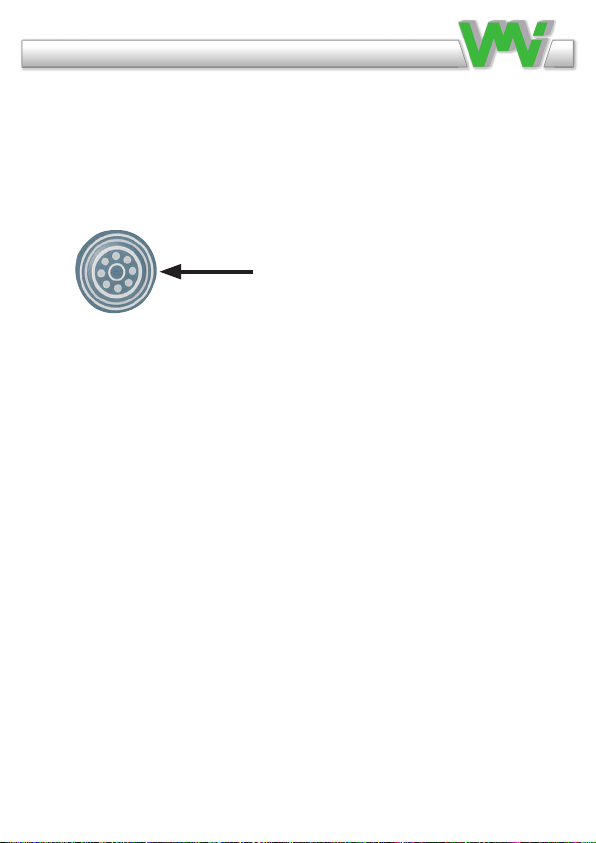
Press the bearing symbol. The instrument measures the bearing
condition value. Bearing condition value is the RMS value of
all high frequency vibrations in the range of 500 Hz to 16 000
Hz. Bearing condition are measured in the unit g.
Bearing condition value
We use acceleration because high frequencies give a larger sig-
nal compared to velocity, if measured in acceleration. When
the balls or rollers rotate inside the bearing, a wide-band noise
and vibration occurs. This noise and vibration increase if the
bearing is poorly lubricated, overloaded due to misalignment
or has a damaged surface.
If the selected frequency band includes low frequencies, the be-
aring condition value would also include vibrations from unba-
lance, misalignment, etc. and not only from bearing vibrations.
Vibraon Measurement Instruments
Press the bearing symbol and the instrument measures the bearing
condition value.
Bearing condition value is RMS value of all high frequency vibra-
tions in the range of 500 Hz to maximum frequency.
This average has the unit g (= m/s²)
Bearing condition value
The bearing condition value in VIBER X1™ is an average value,
RMS value, of all high frequency vibrations between 500 Hz and
maximum frequency.
This value is an average with the unit “g” because high frequen-
cies give a larger signal compared with velocity, if it is measured
in acceleration.
When the balls or rollers rotate inside the bearing a wide-band
noise and vibration arises. This noise and vibration are increased
if the bearing is poorly lubricated, overloaded due to misalignment
or has a damaged surface.
If the selected frequency band includes low frequencies, the
bearing condition value would also include vibrations from
unbalance, misalignment, etc. and not only from bearing vibrations
and would therefore be diffi cult to interpret.
If the selected frequency band only includes very high frequency
noise and vibrations we would need special vibration transducers
that are very rigidly and closely mounted to the bearing because
Bearing condition
Manual Viber X1_121002.indd 14 10/3/12 9:26 AM
Bearing condition symbol

14
Press the bearing symbol and the instrument measures the bearing
condition value.
Bearing condition value is RMS value of all high frequency vibra-
tions in the range of 500 Hz to maximum frequency.
This average has the unit g (= m/s²)
Bearing condition value
The bearing condition value in VIBER X1™ is an average value,
RMS value, of all high frequency vibrations between 500 Hz and
maximum frequency.
This value is an average with the unit “g” because high frequen-
cies give a larger signal compared with velocity, if it is measured
in acceleration.
When the balls or rollers rotate inside the bearing a wide-band
noise and vibration arises. This noise and vibration are increased
if the bearing is poorly lubricated, overloaded due to misalignment
or has a damaged surface.
If the selected frequency band includes low frequencies, the
bearing condition value would also include vibrations from
unbalance, misalignment, etc. and not only from bearing vibrations
and would therefore be difficult to interpret.
If the selected frequency band only includes very high frequency
noise and vibrations we would need special vibration transducers
that are very rigidly and closely mounted to the bearing because
Bearing condition
If the selected frequency band only includes very high fre-
quency noise and vibrations, we would need special vibration
transducers that are very rigidly and closely mounted to the
bearing because the machine structure works as a mechanical
VIBER X
™measures the bearing
condition value between 500 Hz to 16 kHz. Normal machi-
nery vibrations rarely have vibrations above 500 Hz.
Note!
A high bearing condition value is an indication and a recom-
mendation to continue with other fault analysis. High bearing
condition values can appear at gear boxes, converting machi-
nes with cutters and similar machines without any bearing
faults because they “naturally” produce frequencies above 500
Hz.

15
Vibraon Measurement Instruments
the machine structure works as a mechanical fi lter for high
frequencies.
VIBER X1™ is measuring the bearing condition value between
500 Hz to 20 kHz. Within this frequency range a common
experience exist in the evaluation of the bearing condition level.
Normal machinery vibrations rarely have vibrations above 500 Hz.
Note!
A high bearing condition value is an indication and a
recommendation to continue with other fault analysis.
High bearing condition values can appear at gear boxes,
converting machines with cutters and similar machines without
any bearing faults because they “naturally” produce frequencies
above 500 Hz.
Manual Viber X1_121002.indd 15 10/3/12 9:26 AM
Bearing condition value with unit “g” RMS
The diagram below is a guide to identify the bearing condi-
tion value. If vibrations of other causes (e.g. ow surge, gear
mesh) are within in the frequency range 500 – 16 000 Hz this
can give a high bearing condition value, without the bearing
being damaged. A high bearing condition value can also be
indicated if the bearing is poorly lubricated or overloaded.
Vibraon Measurement Instruments
Bearing condition value with unit “g” RMS
The diagram above is a guide to identify the bearing condition
value. If vibrations of other causes (e.g. fl ow surge, gear mesh) are
within in the frequency range 500 – 6400 Hz this can give a high
bearing condition value, without the bearing being damaged.
A high bearing condition value can also be indicated if the bearing
is poorly lubricated or overloaded.
Manual Viber X1_121002.indd 16 10/3/12 9:26 AM
Bearing condition value with unit “g” RMS
The diagram above is a guide to identify the bearing condition
value. If vibrations of other causes (e.g. ow surge, gear mesh) are
within in the frequency range 500 – 16 000 Hz this can give a high
bearing condition value, without the bearing being damaged.
A high bearing condition value can also be indicated if the bearing
is poorly lubricated or overloaded.

16
Bearing condition value with unit “g” RMS
The diagram above is a guide to identify the bearing condition
value. If vibrations of other causes (e.g. ow surge, gear mesh) are
within in the frequency range 500 – 6400 Hz this can give a high
bearing condition value, without the bearing being damaged.
A high bearing condition value can also be indicated if the bearing
is poorly lubricated or overloaded.
Technical data VIBER X
Accelerometer Standard nom 100
mV/g
(Adjusted to the
instrument)
Input amplitude
range
Max 199.9 mm/s
Max 19.99 gBC
Dynamic range 60 dB (159.16 Hz)
Frequency range
10 - 1000 Hz
2 - 30 000 Hz
Available for
500 - 16 000Hz
units mm/s and g-value
Amplitude RMS
Signal processing Analog
Inaccuracy
±4 %
±5 %
Alkaline AAA
LED display 7 segment, 4 digits
IP65
range -20 to 50°C
Weight 285 gram
Size (L x W x H) 125mm x 70mm x 40mm
TM
Minimum 12 hours continuos measuring
two options
Vibration
Bearing condition
Vibration
Bearing condition
Vibra�on
Bearing condi�on

17
TECHNICAL SPECIFICATIONS VIBER X1™
INPUT SENSITIVITY: 100mV/g calibrated at 156.15 Hz.
MEASURING RANGE: Velocity: 0-200 mm/s RMS
FREQUENCY RANGE: Total level 2-3200 Hz
Adjustable filters: 2-10, 1000 - maximum
Hz
Bearing condition 500 Hz – 20 kHz
WEIGHT: 270 gram with accelerometer and
batteries
The measurement mainly follows
ISO10816-3.
ACCURACY*: Better than +/- 3 %
* This value can be higher, close to the filters cut off frequency.
BATTERY TYPE: 3 pc of AAA Rechargeable
VIBRATION TRANSDUCER*
The accelerometer VMI 192 has a sensitivity 100mV/g +/-10%.
MAGNET SUPPORT
Length: 20mm, Diameter: 15mm, Magnet force: about 14kg
Note!
You must avoid to use other accelerometers bacause of the calibration.
If you change accelerometer the instrument must be calibrated to
preserve the accuracy.
Technical data VIBER X
.
You should avoid using other accelerometers
because of instrument calibration. If you
change the accelerometer, the instrument
must be calibrated to preserve the accuracy.
TM
Note 2. Wait until the instrument has stabilized
resonably well, before starting measurement.
Note 1.
18
Technical specifications for VMI 192
Sensitivity (+/-10%) 100mV/g
Frequency response (±3dB) 0.4–13000Hz
(±10%) 1.0-9000Hz
Dynamic Range ±80 g, peak
Internal resonance 26000Hz
Settling time <2 Seconds
Bias Voltage 10-14VDC
Temperature range -50 to 121 °C
Maximum Shock Protection 5000 g, peak
Electromagnetic Sensitivity CE-Certified
Weight (without magnet) 51 grams
Mounting stud M6 Adapter stud
Mounting Torque 2.7-6.8 Nm
• We reserve the right to modify or improve the designs or
specifications of our products at any time without notice.
Declaration of conformity
VMI declares that the Viber X1™ is manufactured in conformity with national and
international regulations.
The system complies with, and is tested according to, following requirements:
EMC Directive: 2004/108/EC
Low Voltage Directive: 2006/95/EC
8 August 2011
Vibration Measurement Instrument International AB (VMI)
•We reserve the right to modify or improve the designs or
Declaration of conformity
VMI declares that the VIBER X
™is manufactured in conformity
with national and international regulations.
The system complies with, and is tested according to, following
requirements:
EMC Directive: 2004/108/EC
Low Voltage Directive: 2006/95/EC
8 August 2011
Technical specifications for VMI 192
Sensitivity (+/-10%) 100mV/g
Frequency response (±3dB) 0.4–13000Hz
(±10%) 1.0-9000Hz
Dynamic Range ±80 g, peak
Internal resonance 26000Hz
Settling time <2 Seconds
Bias Voltage 10-14VDC
Temperature range -50 to 121 °C
Maximum Shock Protection 5000 g, peak
Electromagnetic Sensitivity CE-Certified
Weight (without magnet) 51 grams
Mounting stud M6 Adapter stud
Mounting Torque 2.7-6.8 Nm
• We reserve the right to modify or improve the designs or
specifications of our products at any time without notice.
Declaration of conformity
VMI declares that the Viber X1™ is manufactured in conformity with national and
international regulations.
The system complies with, and is tested according to, following requirements:
EMC Directive: 2004/108/EC
Low Voltage Directive: 2006/95/EC
8 August 2011
Vibration Measurement Instrument International AB (VMI)

19
Vibraon Measurement Instruments
Warranty disclaimer
VMI warrants the products to be free from defects in material and workmanship
under normal use and service within two years from the date of purchase and which
from our examination shall disclose to our reasonable satisfaction to be defective.
Warranty claimed products shall be returned prepaid to VMI for service. We reserve
the right to repair or to replace defective products. Always try to explain the nature
of any service problem; by e-mail or telephone. Check fi rst all natural problems,
like empty batteries, broken cables, etc. If returning the product, be sure to indicate
that the purpose is to make repairs and indicate the original invoice number and
date of shipment.
Warranty exclusions
Damage not resulting from a defect in material or workmanship or by other than
normal use. Damage resulting from repairs performed other than by an authorized
service centre. The limited two year warranty and remedies contained herein are in
lieu of all other warranties, expressed or implied including any warranty of mer-
chantability and any warranty of fi tness for a particular purpose, and all other rem-
edies, obligations or liabilities on our part. In addition, we hereby disclaim liability
for consequential damages for breach of any expressed or implied warranty,
including any implied warranty of merchantability and any implied warranty of
fi tness for a particular purpose. The duration of any implied warranty which might
exist by operation of law shall be limited to one year from the date of original retail
purchase.
NOTE: Some countries do not allow the exclusion or limitation of consequential
damages, and some countries do not allow limitation on how long an implied
warranty lasts, so the above exclusions or limitations may not apply to you. This
warranty gives you specifi c legal rights and you may also have other rights that
vary from country to country. If you have problems with your instrument during or
after the warranty period, fi rst contact your distributor you purchased the unit from.
Manual Viber X1_121002.indd 19 10/3/12 9:26 AM
Warranty disclaimer
VMI warrants the products to be free from defects in material and workmanship
under normal use and service within 2 years from the date of purchase and which
from our examination shall disclose to our reasonable satisfaction to be defective.
Warranty claimed products shall be returned prepaid to VMI for service. We reserve
the right to repair or to replace defective products. Always try to explain the nature
of any service problem by lling in the form found on the website www.vmiab.com
and attach it in an email to VMI. Check rst all natural problems, like empty batte-
ries, broken cables, etc. If returning the product, be sure to indicate that the purpose
is to make repairs and indicate the original invoice number and date of shipment.
Warranty exclusions
Damage not resulting from a defect in material or workmanship or by other than
normal use. Damage resulting from repairs performed other than by an authorized
service center. The limited two year warranty and remedies contained herein are in
lieu of all other warranties, expressed or implied including any warranty of mer-
chantability and any warranty of tness for a particular purpose, and all other reme-
dies, obligations or liabilities on our part. In addition, we hereby disclaim liability
for consequential damages for breach of any expressed or implied warranty, inclu-
ding any implied warranty of merchantability and any implied warranty of tness
for a particular purpose. The duration of any implied warranty which might exist by
operation of law shall be limited to one year from the date of original retail
purchase.
NOTE: Some countries do not allow the exclusion or limitation of consequential
damages, and some countries do not allow limitation on how long an implied
warranty lasts, so the above exclusions or limitations may not apply to you. This
warranty gives you specic legal rights and you may also have other rights that
vary from country to country. If you have problems with your instrument during or
after the warranty period, rst contact your distributor you purchased the unit from.

VMI International AB
Sweden • www.vmiab.com
This manual suits for next models
5
Table of contents
Other VMI Measuring Instrument manuals


Popular Measuring Instrument manuals by other brands

Audioscope
Audioscope 3000 operating instructions

Evoqua
Evoqua WALLACE & TIERNAN DEPOLOX 5 E instruction manual

National Instruments
National Instruments PXIe-4163 Getting started guide

DEWESOFT
DEWESOFT SIRIUS Technical reference manual

PCE Instruments
PCE Instruments PCE-VT 3700-ICA user manual

Kobold
Kobold APS-Z operating instructions


