Mercury SC1000 User manual

© 2018 Mercury Marine SC 1000 Tachometer/Speedometer
8M0147197 518 eng

eng

Product Overview
Basic Operation and Features............................................................................ 1
Alarm Warnings with Descriptive Text................................................................ 2
Alarm Warnings with Universal Codes............................................................... 4
Master Reset...................................................................................................... 5
Descriptive Fault Text Warning Display Screens................................................ 6
Display Screens................................................................................................ 10
SC 1000 Tachometer
System Tachometer Display Screens............................................................... 11
Maintenance Screen......................................................................................... 13
Sport Exhaust Screen....................................................................................... 14
Tachometer Settings ‑ MENU........................................................................... 15
Tachometer Settings ‑ SCREENS.................................................................... 17
Tachometer Settings ‑ CALIBRATION............................................................. 19
SC 1000 Speedometer
Speedometer Display Screens......................................................................... 26
Speedometer Settings ‑ MENU........................................................................ 28
Speedometer Settings ‑ SCREENS.................................................................. 30
Speedometer Settings ‑ CALIBRATION........................................................... 31
Troll Control
Troll Control Operation..................................................................................... 34
Smart Tow
Cruise Control Operation.................................................................................. 37
Precise Speed Control Calibration (Optional)................................................... 38
Launch Control Operation................................................................................. 40
Creating a Customized Launch Setting............................................................ 42
eng i

Active Trim
Requirements................................................................................................... 45
Introduction to Active Trim................................................................................ 45
Active Trim Operation....................................................................................... 46
Setup and Configuration................................................................................... 47
ii eng

Basic Operation and Features
NOTE: Descriptive text alarm warning screens are displayed with 2007 and
newer engines. Universal fault codes can be utilized with specific Outboard and
MerCruiser products produced 2015 and newer.
46346
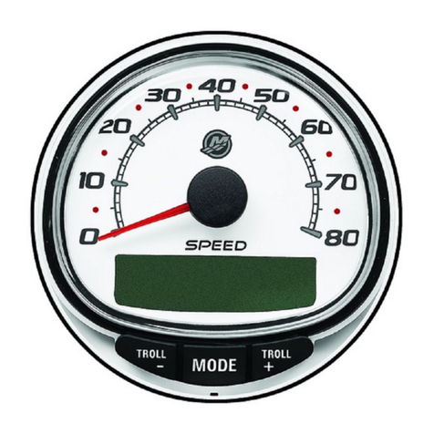
System Tachometer System Speedometer
Power up: Each gauge will power up when the ignition is turned on. The
gauges will stay on as long as the ignition is on.
Lights: Adjusts the brightness and contrast of the gauge.
Buttons: The "MODE/SELECT" button is used for selecting information
screens. The "+" and "–" buttons are used for setting engine speed for troll
control, and setting gauge calibrations.
Troll control: Sets and controls the idle speed of the engine for trolling without
using the throttle.
Engine Guardian System: Monitors the critical sensors on the engine for any
early indication of problems. The system will respond to a problem by reducing
engine speed and alerting the operator to a potentially damaging situation.
Warning system: The system sounds the warning horn and displays the
warning with descriptive text or a fault code.
IMPORTANT: Optional sensors such as depth, fuel, paddle wheel, and steering
angle, should always be connected to the starboard engine when using
SmartCraft gauges version 4.0 or later.
PRODUCT OVERVIEW
eng 1

PRODUCTS WITH EMISSIONS CONTROL
After the ignition is turned on, the tachometer will display the name of the
gauge and the version of the software for approximately two seconds. In the
upper left‑hand corner of the display, a small engine icon will also be visible.
The engine icon indicates the power package has emissions control onboard
diagnostics, also known as OBD. The icon will only be seen during the key up
process unless a system fault is detected. When a fault is detected, the OBD
icon will be displayed in the upper left‑hand corner on all system screens.
a - OBD icon
b - Software version
Alarm Warnings with Descriptive Text
Descriptive text alarm warning screens are displayed with 2007 and newer
engines.
a - Display screen
b - Engine Guardian System
c - Alarm signal
When a problem is detected, the name of the offending alarm appears on the
display.
MERCURY
13469
S Cmart raft v X.X
a
b
a
3200RPM
AL
bc
REDUCE
THROTTLE
46348
PRODUCT OVERVIEW
2 eng

If the problem can cause immediate engine damage, the Engine Guardian
System will respond to the problem by limiting engine power. Immediately
reduce the throttle speed and refer to the warning messages on the following
pages. Refer to the Operation and Maintenance Manual for further
explanation of the problem and the correct action to take.
When a problem is detected, "SYS FAULT" screen will flash and the display will
show the fault location and information.
If the "MODE/SELECT" button is pressed to display a different screen, the
flashing alarm signal "AL" will appear in the upper‑right corner to indicate there
still is a problem.
Alarm Warning with Descriptive Text
[ SHOW ]
SYS FAULT
24184
The "SYS FAULT" flashing screen appears
when there is a problem in the system.
The screen will alternately flash the text in
the top half of the screen, and in the
bottom half of the screen.
[MORE ]
STBD
[EXIT]
58124
[NEXT]
The text displays the fault location
("STBD," "PORT," "HELM 1," "HELM 2")
and will flash the following screen with a
general description of the fault.
[MORE ]
<FAULT COMPONENT>
[EXIT]
58125
[NEXT]
The scrolling text displays a general
description of the fault and will flash the
previous screen. The flashing screens will
continue until "NEXT" is selected. "MORE"
displays a detailed description of the fault.
[ACTION ]
<FAULT DESCRIPTION>
58117
[EXIT] [NEXT]
The scrolling text displays a detailed
description of the fault. "NEXT" displays
the next fault. "ACTION" displays the
corrective action.
[BACK ]
<CORRECTIVE ACTION>
[EXIT]
58126
[NEXT]
The corrective action for the fault is
displayed. "NEXT" displays the next fault.
"BACK" returns to the previous screen.
EMISSION CONTROL FAULTS WITH DESCRIPTIVE TEXT
When a problem is detected with the emission control system, the screen will
flash between an engine icon that shows the text "OBD SERVICE SOON" and
the system fault screen. These two screens will flash and then display the fault.
PRODUCT OVERVIEW
eng 3

If the problem can cause immediate engine damage, the Engine Guardian
System will respond to the problem by limiting engine power. Immediately
reduce the throttle speed and refer to the warning messages on the following
pages. Refer to the Operation and Maintenance Manual for further
explanation of the problem and the correct action to take.
The alarm message will remain displayed until the "EXIT" button is pressed.
If the "MODE/SELECT" button is pressed to display a different screen, the
engine emission fault alarm icon will appear in the upper left‑hand corner. The
engine icon will be visible on all screens. A servicing dealer must diagnose the
emission control faults and correct the problem prior to the next use of the
vessel.
Emission Control Faults With Descriptive Text
46456
OBD SERVICE SOON
An engine icon will appear in the middle of
the screen with text stating "OBD
SERVICE SOON." The screen will flash to
the "SYS FAULT" screen approximately
every three seconds.
[MORE ]
STBD
[EXIT]
58124
[NEXT]
The text displays the fault location
("STBD," "PORT," "HELM 1," HELM 2")
and will flash the following screen with a
general description of the fault.
[MORE ]
<FAULT COMPONENT>
[EXIT]
58125
[NEXT]
The scrolling text displays a general
description of the fault and will flash the
previous screen. The flashing screens will
continue until "NEXT" is selected. "MORE"
displays a detailed description of the fault.
[ACTION ]
<FAULT DESCRIPTION>
58117
[EXIT] [NEXT]
The scrolling text displays a detailed
description of the fault. "NEXT" displays
the next fault. "ACTION" displays the
corrective action.
[BACK ]
<CORRECTIVE ACTION>
[EXIT]
58126
[NEXT]
The corrective action for the fault is
displayed. "NEXT" displays the next fault.
"BACK" returns to the previous screen.
Alarm Warnings with Universal Codes
Universal fault codes are only available on specific Outboard and MerCruiser
products produced 2015 and newer.
When a problem is detected, the name of the offending alarm appears on the
display.
PRODUCT OVERVIEW
4 eng

If the problem can cause immediate engine damage, the Engine Guardian
System will respond to the problem by limiting engine power. Immediately
reduce the throttle speed and refer to the warning messages on the following
pages. Refer to the Operation and Maintenance Manual for further
explanation of the problem and the correct action to take.
When a problem is detected, "SYS FAULT" screen will flash and the display will
show the fault location and information.
If the "MODE/SELECT" button is pressed to display a different screen, the
flashing alarm signal "AL" will appear in the upper‑right corner to indicate there
still is a problem.
Alarm Warning with Universal Codes
[ SHOW ]
SYS FAULT
24184
The "SYS FAULT" flashing screen appears
when there is a problem in the system.
The screen will alternately flash the text at
the top half of the screen, and at the
bottom half of the screen.
[MORE ]
STBD
[EXIT]
58127
The text displays the fault location
("STBD," "PORT," "HELM 1," "HELM 2").
When there is more than one fault location,
the text will scroll. "MORE" displays the
fault code.
[NEXT ]
621-25
[EXIT]
58128
The fault is displayed as a numerical code.
The code description is listed in the
operation manual included with the
product. When there is more than one
code, "NEXT" displays the sequential fault
code.
Master Reset
Returns the gauge to the factory defaults through the Master Reset command.
IMPORTANT: Performing a Master Reset will reset the unit to the factory
defaults, thus eliminating any installation settings and calibrations performed
during set up of product.
PRODUCT OVERVIEW
eng 5

Press the "‑" and "+" buttons simultaneously for approximately 10 seconds
(until the graphic bars collide) to restore the unit to factory default settings.
Press the "MODE/SELECT" button to confirm.
22660
MASTERRESET
MASTERRESET
ERASE CALIBRATION !
PRESS MODE/SELECT TO CONFIRM
Descriptive Fault Text Warning Display Screens
When a problem is detected with the engine, the warning display screens will
alert the operator to the potential problem. Refer to the Operation and
Maintenance Manual for an explanation of the problem and the correct action
to take.
PROBLEM TACHOMETER DISPLAY SPEEDOMETER
DISPLAY
BATTERY ×
ENGINE DATA BUS ×
FAULT ‑ HORN ×
FAULT ‑ IGNITION ×
FAULT ‑ INJECTOR ×
FAULT ‑ OIL PUMP ×
FAULT ‑ SENSOR ×
FAULT ‑ WATER TEMP ×
LOW FUEL ×
LOW OIL ×
FAULT ‑ OIL TEMP ×
OIL PSI ×
OVERHEAT ×
OVERSPEED ×
FAULT ‑ OIL PRESSURE ×
RESERVE OIL ×
SYSTEM FAULT –
OBD SERVICE SOON ×
WATER IN FUEL ×
FAULT ‑ MAP ×
PRODUCT OVERVIEW
6 eng

PROBLEM TACHOMETER DISPLAY SPEEDOMETER
DISPLAY
FAULT ‑ MAT ×
FAULT ‑ TPS ×
Oil level ‑ OK x x
Oil level LOW ‑ Check OIL x x
NOTE: Depending on the engine model and vessel options, not all screens will
apply.
FAULT
RESERVE
FAULT
FAULT
HORN
90% REMAINING
OIL PUMP
INJECTOR
46351
5
6
7
8
OVERHEAT
PRESSURE
OVERSPEED
WATER
7500 RPM
IN FUEL
1
2
3
4
IMPORTANT: Refer to the Operation and Maintenance Manual for further
explanation of the problem and the correct action to take. Contact the dealer if
the problem persists.
1. OVERHEAT: The engine has overheated.
2. PRESSURE: There is insufficient water pressure in the cooling system.
3. OVERSPEED: Engine speed exceeded the maximum allowable RPM.
4. WATER IN FUEL: Water in the water‑separating fuel filter reached the full
level.
5. FAULT ‑ HORN: The warning horn is not functioning correctly.
6. RESERVE OIL LOW ‑ 2‑Stroke outboard only: Oil level is critically low
in the engine‑mounted oil reservoir tank.
7. FAULT ‑ OIL PUMP: The oil pump has stopped functioning electrically.
No lubricating oil is being supplied to the engine.
8. FAULT ‑ INJECTOR: One or more of the fuel injectors have stopped
functioning electrically.
PRODUCT OVERVIEW
eng 7

NOTE: Depending on the engine model and vessel options, not all screens will
apply.
FAULT
BATTERY
FAULT
FAULT
FAULT
FAULT
FAULT
SENSOR
WATER TEMP
OIL TEMP
46353
ENGINE
DATA BUS
IGNITION
NO STARBOARD
ENGINE
MULTIPLE STARBOARD
ENGINE
8V 18V
9
10
11
12
13
14
15
16
9. FAULT ‑ IGNITION: A problem has developed in the ignition system.
10. BATTERY: The electrical system is not charging or the battery charge is
low.
11. ENGINE DATA BUS: The data communication link between the
tachometer and engine is not connected.
12. FAULT ‑ SENSOR: One of the sensors is not functioning correctly.
13. FAULT ‑ WATER TEMP: The sensor for measuring outside lake/seawater
temperature is not functioning correctly.
14. FAULT ‑ NO STARBOARD ENGINE: The instrument does not detect the
starboard engine computer. This usually indicates that no data is being
transferred from the engine's computer to the gauge. Check the wiring.
Make sure both terminator resistors are installed in the bus. Make sure
the PCM/ECM's are not configured for the same location using computer
diagnostic system (CDS).
15. FAULT ‑ MULTIPLE STARBOARD ENGINE: SmartCraft gauges are
recognizing multiple engines as starboard.
NOTE: In multiple engine applications, each engine must be assigned a
position (starboard, port, starboard2, or port2) by an authorized dealer before
the system will function properly.
16. FAULT ‑ OIL TEMP: The engine oil is overheating.
PRODUCT OVERVIEW
8 eng

NOTE: Depending on the engine model and vessel options, not all screens will
apply.
FAULT
LOW FUEL
LOW OIL
FAULT
FAULT
FAULT
MAP
MAT
TPS
OIL PRESSURE
E F
EF
17
18
19
21
22
[ SHOW ]
SYS FAULT
OBD SERVICE SOON
23
Oil Level
OK
19
20
Oil Level
LOW - Check OIL 25
24
67155
17. FAULT ‑ OIL PRESSURE: There is insufficient oil pressure.
18. LOW FUEL LEVEL: The fuel level in the fuel tank is critically low. Stop for
fuel immediately to avoid running out.
19. LOW OIL LEVEL ‑ 2‑Stroke outboard only: The oil level in the remote
oil tank is low. Stop and fill the oil tank immediately to avoid running out.
20. Oil Level ‑ OK ‑ 4‑Stroke outboard only: The oil level in the engine is
OK.
21. FAULT ‑ MAP: Engine problem occurred. Have the engine checked by a
dealer.
22. FAULT ‑ MAT: Engine problem occurred. Have the engine checked by a
dealer.
23. FAULT ‑ TPS: Engine problem occurred. Have the engine checked by a
dealer.
24. SYSTEM FAULT ‑ OBD SERVICE SOON: A problem has occurred with
the engine emissions control system. Have the engine checked by a
dealer.
25. Oil Level ‑ LOW ‑ Check OIL ‑ 4‑Stroke outboard only: The oil level in
the engine is low. Check the engine oil level. Refer to the Operation
Manual for the detailed procedure.
PRODUCT OVERVIEW
eng 9

Display Screens
Tachometer Display Screen Speedometer Display Screen
Engine Break‑in (2‑Stroke outboard only) Clock ‑ Air/Sea Temp
Engine Temperature Fuel Used
Oil Temperature Cog ‑ If there is a GPS input
Oil PSI Distance and Fuel to Waypoint
Trim and RPM Speed
Trim and Water Pressure Estimated Range
Water Pressure Instant and Average Fuel Economy
Battery Voltage and Engine Hours Trip Odometer
Fuel Flow and Fuel Used Fuel Tank Levels
Speed and Sea Temperature Oil Tank Levels
Battery Voltage Fresh Water Levels
% Fuel Remaining (Fuel Tank 1) Waste Water levels
Depth Steering Angle (MerCruiser only)
Trim Position Tabs
Fuel PSI Dual Engine
RPM Trim and RPM Synchronizer
Maintenance
Quick Reference Screen
Battery, Temperature, PSI
Active Exhaust (if equipped)
Active Trim (if equipped)
PRODUCT OVERVIEW
10 eng

System Tachometer Display Screens
When the ignition is turned on, the tachometer will display the last screen that
was visible before the ignition was turned off.
Press "MODE/SELECT" to change display screens. Revert back to the
previous screen by pressing and holding "MODE/SELECT" for two seconds.
NOTE: Readings can be displayed in English (U.S.) or metric. Refer to
Tachometer Screens
.
NOTE: Depending on the engine model and vessel options, not all screens will
apply.
F
125
1
2
3
4
5
6
7
OIL
PSI
12.5
150 HOT
F
OIL
COLD
50349
TRIM WATER PSI
12.51.5
TRIM RPM
22051.5
12.5 H20
PSI
VOLTS HOURS
12.2 1.5
1. Temperature: Displays the engine coolant temperature.
2. Oil Temperature: Displays the engine oil temperature.
3. Oil Pressure: Displays the engine oil pressure in "PSI" or "BAR."
4. Trim and RPM: Displays the engine RPM and trim position.
5. Power Trim Angle: Displays the trim angle of the outboard or sterndrive
up to the maximum trim angle and then displays the trailer angle. 0 =
down, 10 = maximum trim, and 25 = full trailer.
6. Water Pressure: Displays the cooling system water pressure at the
engine.
SC 1000 TACHOMETER
eng 11

7. Battery Voltage: Displays the voltage level (condition) of the battery. Also
records the running time of the engine.
RPM
3500
GPH USED
12.5
4.5
FUEL
SPEED SEA TEMP
MPH
45 45 F
35 FT
OK OK OK
BAT TMP PSI
MAINTENANCE
OK [ENTER]
12.5
-
v50352
8
9
10
11
12
13
14
8. Fuel Flow: Displays fuel use in gallons or liters per hour, and overall
amount of fuel used.
9. Digital Tachometer: Displays the engine speed in revolutions per minute
(RPM).
10. Maintenance: Displays if the engine is "OK" or that it requires scheduled
maintenance. This maintenance screen is based on a 100 hour
maintenance cycle. Follow the maintenance schedule recommendation in
the owner's manual.
NOTE: The scheduled maintenance cycle should be reset following
maintenance performed at the Once a Year and Before Storage
recommendation that is indicated in the owner's manual.
11. Water Depth: Displays the water depth under the transducer if
connected. The water depth screen can be turned on or off in
Tachometer Screens. The alarm can be set to trigger whenever the boat
moves into water shallower than the alarm level. Refer to Tachometer
Screens for water depth alarm and offset settings.
NOTE: A depth transducer (purchased separately) must be connected to the
system for this screen to operate.
12. Speed/Temp: Displays a split screen of seawater temperature and vessel
speed.
NOTE: A speed input sensor must be connected to the system for this screen
to operate.
SC 1000 TACHOMETER
12 eng

13. Quick Reference Screen: Indicates that the battery, engine temperature,
and pressures are operating properly.
14. Battery Voltage: Displays in large numbers the current voltage of the
battery.
BREAK-IN TIME
MIN
LEFT
65
FUEL
PSI
43.5
TRIM 1.5
65 %
50353
15
16
17
18
15. Power Trim Angle/Water Pressure: Displays the trim angle of the
engine and cooling system water pressure.
16. Fuel Percentage: Displays the percentage of fuel that is in the fuel tank.
17. Fuel Pressure: Displays the engine fuel pressure.
18. Engine Break‑in: Displays the time remaining on the break‑in period of a
new engine. This screen will automatically disappear after the break‑in
period is complete.
Maintenance Screen
Some 4‑stroke power package models have the ability to estimate the amount
of run time the engine accumulated since the last scheduled maintenance.
Normal scheduled maintenance for the engine is 100 hours. The maintenance
screen shows a bar graph approximating the amount of time remaining before
a scheduled maintenance is required. When the maintenance screen is reset,
the bar graph will change to represent the scheduled maintenance has 100
hours remaining. The maintenance screen must be turned on for this screen to
be displayed. Your owner's manual maintenance schedule should be followed
regardless of what the gauge displays. To turn this feature on, refer to
Tachometer Display Screens.
SC 1000 TACHOMETER
eng 13

1. When the maintenance screen is displayed, press "ENTER" to see the
approximate amount of time remaining before a scheduled maintenance
is recommended.
50359
MAINTENANCE
OK [ENTER]
SCHED. MAINTENANCE
OK
OK
[EXIT] [RESET]
PERFORM SCHEDULED MAINTENANCE
OK
[EXIT] [RESET]
MAINTENANCE
[ NO ][YES ]
HAS SCHEDULED MAINT.
BEEN PERFORMED?
SCHED. MAINTENANCE
OK
OK
[EXIT] [RESET]
1
2
3
4
5
2. The scheduled maintenance screen displays a bar graph indicating the
estimated time remaining on the scheduled maintenance cycle. Press
"EXIT" to return to the previous screen or "RESET" after the scheduled
maintenance has been performed.
3. If the amount of time since the last scheduled maintenance has passed
100 hours, the screen will show "PERFORM SCHEDULED
MAINTENANCE" and the bar graph will not be visible. Press "EXIT" to
return to the previous screen or "RESET."
4. After pressing "RESET" the screen goes to the "MAINTENANCE" screen.
The "MAINTENANCE" screen will display "HAS SCHEDULED MAINT.
BEEN PERFORMED?" Press "YES" to reset the maintenance schedule,
or press "NO" to return to the previous screen.
5. After pressing "YES" the screen will show the bar graph has been reset to
represent 100 hours of operation before the next scheduled maintenance.
Press "EXIT" to return the "MAINTENANCE OK" screen.
Sport Exhaust Screen
SPORT EXHAUST OVERVIEW
The Sport Exhaust feature allows the operator to change the sound of the
outboard idle relief exhaust volume. This enables the Sport Exhaust feature to
open an exhaust passage, allowing a more deep exhaust sound.
REQUIREMENTS
This feature is not available on all models. Refer to engine owner's manual for
more information.
SC 1000 TACHOMETER
14 eng

SPORT EXHAUST OPERATION
Sport Exhaust Display Screens
( NO ) (SAVE) ( YES )
67159
SPORT EXH. SCREEN ?
Select "YES" to enable the Sport Exhaust
feature, or "NO" to disable the Sport Exhaust
feature.
Tachometer Settings ‑ MENU
46369
1. Press the "MODE/SELECT" and "+" buttons simultaneously for
approximately two seconds or until the "MENU" screen appears.
2. Press the "+" or "–" to change the settings.
MENU
[SKIP] [ EDIT ]
MENU
SPEED CONTROL ?
67187
Selects how speed should be controlled.
Press "+" to select "EDIT" or "MODE/
SELECT" to bypass speed control.
[SAVE] [ YES ]
SPEED CONTROL
TROLL CONTROL ?
[ NO ]
ENABLED
52680
Troll control must be enabled on the
tachometer to use engine RPM. Using
engine RPM to control the troll function will
cause the vessel speed to vary based on
conditions the vessel encounters: wind,
waves, or current.
LIGHT
[DOWN] [SAVE] [ UP ]
23517
Adjusts the brightness of the gauge
lighting.
SC 1000 TACHOMETER
eng 15

MENU
CONTRAST
[DOWN] [SAVE] [ UP ]
23519
Adjusts the contrast of the display screen.
[ NO ] [SAVE] [YES ]
23532
REMOTE LCD LIGHT ?
Adjusts the lighting levels on all gauges
simultaneously from this gauge. If "YES" is
selected, then lighting level changes made
on this tachometer will effect all
tachometers in the system. All
tachometers need the screen set to "YES"
for this function to work.
[ NO ] [SAVE] [YES ]
23533
REMOTE LCD CONTRAST ?
Adjusts the contrast of another System
Tachometer simultaneously from this
gauge. If "YES" is selected, then contrast
level changes made on this tachometer will
effect all tachometers in the system. All
tachometers need the screen set to "YES"
for this function to work.
SPLASH SCREEN
[SKIP] [ EDIT ]
46447
MERCURY
You can edit the name of the splash
screen. Press "+" to edit the name, or
press "MODE/SELECT" to skip changing
the splash screen name.
SPLASH SCREEN
[DOWN] [ UP ]
30246
_MERCURY
[NEXT]
The splash screen name has nine spaces
for characters. 59 characters, including an
empty character, is available for each
space. Press the "–" or "+" button to
change the character. Press the "MODE/
SELECT" button to move to the next
space. All nine splash screen name
spaces must be selected before exiting the
splash screen option.
[DOWN] [ UP ]
LOCAL LIGHT
[SAVE]
52644
Allows you to control the light level of the
local screen.
[YES ]
UNIVERSAL FAULTS?
[NO]
58130
[SAVE]
NO
Allows you to turn the universal fault codes
on ("YES") or off ("NO"). When universal
fault codes are turned on, descriptive text
is not available. The default setting is
"NO."
SC 1000 TACHOMETER
16 eng
Other manuals for SC1000
2
Table of contents
Other Mercury Measuring Instrument manuals
Popular Measuring Instrument manuals by other brands

METREL
METREL EurotestCOMBO MI 3125 instruction manual

Compact
Compact STE 3 instructions

Brookfield
Brookfield DV2T operating instructions

VOLTCRAFT
VOLTCRAFT Gamma Check Pro operating instructions

Associated Research
Associated Research LVB-2 instruction sheet

ElektroPhysik
ElektroPhysik MiniTest 403 Technical Reference and Operating Manual