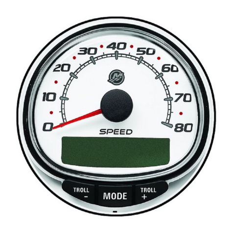
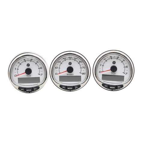
Mercury 8M0104800 User manual

90-8M0104800 MARCH 2015 © 2015 Mercury Marine Page 1 / 6
SMART TACHOMETER, SMART
SPEEDOMETER INSTALLATION
IMPORTANT: This document guides our dealers, boatbuilders, and company service personnel in the proper installation or
service of our products. If you have not been trained in the recommended servicing or installation procedures for these or
similar Mercury Marine products, have the work performed by an authorized Mercury Marine dealer technician. Improper
installation or servicing of the Mercury product could result in damage to the product or personal injury to those installing or
operating the product.
NOTE:
After completing installation, place these instructions with the product for the owner's future use.
Installation Information
Before cutting any holes, check area behind dashboard for obstructions (braces, cables, wiring, etc.).
When cutting the dashboard for gauge installation, follow these cutting tips:
• Fiberglass – Apply masking tape to area to be cut to prevent dashboard from cracking.
• Vinyl covered – Remove vinyl from area to be cut with razor blade to keep vinyl from tearing.
Outside Air Temperature Sensor Installation
IMPORTANT: Do not allow electrical connections to flex. Fasten all electrical harnesses within 25 cm (10 in.) of the
connection. Ensure all unused harness connectors are protected with weather caps.
1. Mount the air temperature sensor where it will be exposed to outside air and will not be in direct sunlight.
2. Select a location and drill a 19 mm (0.750 in.) mounting hole.
3. Install the mounting adapter.
4. Thread the air temperature sensor into the mounting adapter.
a - Mounting adapter
b - Gasket
c - Dashboard
d - Nylon nut
e - Air temperature sensor
Gauge Installation
1. Disconnect both battery cables from the battery.
! WARNING
Performing service or maintenance without first disconnecting the battery can cause product damage, personal injury, or
death due to fire, explosion, electrical shock, or unexpected engine starting. Always disconnect the battery cables from the
battery before maintaining, servicing, installing, or removing engine or drive components.
2. Select a location for the gauge that has unobstructed visibility.
! CAUTION
Avoid injury or product damage. Obstructions, such as braces and wiring, may be unseen when looking at the front of the
dashboard. Before drilling or cutting any holes in the dashboard, check the area behind the dashboard for obstructions. Do
not drill or cut when obstructions are present.
ab
c
de
4322

SMART TACHOMETER, SMART SPEEDOMETER INSTALLATION
Page 2 / 6 90-8M0104800 MARCH 2015
3. Use a 86 mm (3.375 in.) diameter hole saw to cut out the opening for the gauge.
3-3/8 in.
(86 mm)
4319
4. Install the seal onto the gauge.
5. Install the gauge with the seal into the dashboard opening and secure with the retainer nut. Tighten the nut securely.
4320
Speedometer Wiring
IMPORTANT: Do not allow electrical connections to flex. Fasten all electrical harnesses within 25 cm (10 in.) of the
connection. Ensure all unused harness connectors are protected with weather caps.
a - Junction box
b - Air temperature sensor
c - Speedometer harness
d - System speedometer
e - NMEA 0183 connection (optional)
a
b
c
d
e
46331

SMART TACHOMETER, SMART SPEEDOMETER INSTALLATION
90-8M0104800 MARCH 2015 Page 3 / 6
Tachometer Wiring
IMPORTANT: Do not allow electrical connections to flex. Fasten all electrical harnesses within 25 cm (10 in.) of the
connection. Ensure all unused harness connectors are protected with weather caps.
a - Junction box
b - Tachometer harness
c - System link gauge (optional)
d - System tachometer
e - Warning horn (optional)
Smart Tow
Smart Tow Tachometer Wiring (RPM Control)
IMPORTANT: Multiple engine applications using only one Smart Tow Tachometer, must have the Smart Tow Tachometer
connected to the starboard engine. Multiple Smart Tow Tachometer applications must have the Smart Tow Tachometers
programmed for their specific engine location.
a - Junction box
b - Tachometer harness
c - System link gauge (optional)
d - Smart Tow Tachometer
e - Warning horn (optional)
Smart Tow Speedometer with SmartCraft GPS Wiring (RPM or Speed Control)
IMPORTANT: Do not allow electrical connections to flex. Fasten all electrical harnesses within 25 cm (10 in.) of the
connection. Ensure all unused harness connectors are protected with weather caps.
1. Connect the antenna harness to the SmartCraft GPS antenna.
2. Mount the SmartCraft GPS antenna in a location with an unobstructed view of the sky. The antenna can be mounted
either flush or on a 2.54 cm (1.0 in.) diameter pole. Refer to SmartCraft Global Positioning System Antenna.
3. Connect the antenna harness to the junction box.
46332
ab
c
d
e
46333
ab
c
d
e

SMART TACHOMETER, SMART SPEEDOMETER INSTALLATION
Page 4 / 6 90-8M0104800 MARCH 2015
IMPORTANT: Multiple engine applications must have the Smart Tow Speedometer harness connected to the helm
harness connector identified with a tag stating "Gauges." When using a GPS antenna, the Smart Tow Speedometer
harness and the GPS antenna must be connected to the helm harness connector identified with a tag stating "Gauges"
through a junction box. This connection ensures the gauge and the antenna have power when any key is turned on.
a - Optional GPS antenna installation
b - GPS antenna
c - Screw and lockwasher (3 each)
d - Antenna harness
e - Junction box
f - Air temperature sensor
g - Speedometer harness
h - Smart Tow Speedometer with GPS
i - NMEA 0183 device
j - Helm harness connector "Gauges"
SmartCraft Global Positioning System Antenna
SmartCraft GPS Mounting Considerations
The selection of a suitable mounting location is important for the optimal performance of the GPS unit. The mounting location
and position of the GPS should be:
•Level with the earth’s horizontal plane—This gives the GPS antenna the optimal view of satellites from all directions.
•High enough to have a clear view of the sky to the horizon in all directions unblocked by masts or antennas—
The GPS provides the best information when it has access to as many satellites as possible. Obstructions within 10
degrees of the horizon will not affect GPS reception.
•At least 61 cm (24 in.) from VHF, satellite, or radar antennas—Radio frequency transmissions from these antennas
can interfere with the reception of the GPS satellite signals.
•Above or below the horizontal plane of any radar transmitter—Avoids radar signal interference.
Installation
Mount the GPS antenna in a location without any overhead obstructions. The antenna can be mounted flush to the surface, or
on a 1.0 in. x 14 threads per inch standard marine pole mount.
a
b
c
d
efg
h
46336
j
I
i

SMART TACHOMETER, SMART SPEEDOMETER INSTALLATION
90-8M0104800 MARCH 2015 Page 5 / 6
Flush Mount Surface
1. Use the dimensions provided to mark and drill the necessary holes for mounting the GPS to a flush mount surface.
View from bottom. Template is not to scale.
a - Connector for harness
b - Holes for fasteners (3)
2. Secure the GPS antenna to the flush mount surface with three brass lockwashers and screws. Tighten the screws
securely.
3. Connect the antenna harness to the GPS.
a - GPS antenna
b - 25.4 mm (1 in.) hole
c - Lockwasher
d - Screw
e - Antenna harness
Marine Pole Mount
NOTICE
Avoid damage to the antenna harness and the GPS antenna. The marine pole mount assembly must be completely
installed and secured to the vessel before the SmartCraft GPS Antenna can be fastened to the antenna mount.
1. Thread the antenna mount onto a standard mount pole. Tighten the antenna mount assembly securely.
2. Thread the antenna mount assembly into the mount base and tighten securely.
3. Guide the antenna harness through the mount base and through the antenna mount assembly.
4. Thread the antenna harness onto the GPS. Tighten securely.
53.6 mm
(2.1 in.)
25.4 mm
(1.0 in.)
ab
31115
b
a
c
d
e
31116

SMART TACHOMETER, SMART SPEEDOMETER INSTALLATION
Products of Mercury Marine © MERCURY MARINE. All rights reserved. Reproduction in whole or in part without permission is
prohibited. Alpha, Axius, Bravo One, Bravo Two, Bravo Three, Circle M with Waves Logo, K-planes,
Mariner, MerCathode, MerCruiser, Mercury, Mercury with Waves Logo, Mercury Marine, Mercury
Precision Parts, Mercury Propellers, Mercury Racing, MotorGuide, OptiMax, Quicksilver, SeaCore,
Skyhook, SmartCraft, Sport-Jet, Verado, VesselView, Zero Effort, Zeus, #1 On the Water and We're
Driven to Win are registered trademarks of Brunswick Corporation. Pro XS is a trademark of Brunswick
Corporation. Mercury Product Protection is a registered service mark of Brunswick Corporation.
W6250 Pioneer Road
Fond du Lac, WI 54936-1939
Page 6 / 6 90-8M0104800 MARCH 2015
5. Secure the GPS antenna to the antenna mount with the three brass lockwasher and screws. Tighten the screws
securely.
a - GPS antenna
b - Harness
c - Antenna mount
d - Lockwasher
e - Screw
f - Pole
31118
a
b
c
d
e
f
Table of contents
Other Mercury Measuring Instrument manuals
Popular Measuring Instrument manuals by other brands

Hioki
Hioki RM3544 instruction manual

Emerson
Emerson FloBoss 103 instruction manual

Pulsar
Pulsar DFM 6.1 instruction manual

Fukuda
Fukuda VaSera VS-2000 Series Operation manual

HunterLab
HunterLab ColorFlex EZ Tomato user manual

Endress+Hauser
Endress+Hauser Prosonic S FMU90 PROFIBUS DP operating instructions