Merida TEAM TR DROPPER SEATPOST User manual

1 2
ABOUT USER MANUAL
• Read and follow the instructions.
• Keep the instructions.
• Read and follow the safety instructions.
SAFETY INSTRUCTIONS
RISK OF INJURY THROUGH IMPROPER ASSEMBLY!
• Do not assemble the seat post yourself. Do not change defective parts yourself.
• Have assembly / repairs carried out by a bicycle mechanic only.
SERIOUS INJURIES FROM DISMANTLING PRESSURIZED PARTS!
The seat post is high filled.
• Do not disassemble the seat post.
• Do not unscrew the upper protective cap of the seat post.
• Make sure that the protective cap is always firmly tightened.
RISK OF ACCIDENT FROM IMPROPERLY ATTACHED ACCESSORIES!
It could impair the function, lead to functional loss and lead to riders falls, accidents and
injuries.
• Do not mount clamps, saddlebags, luggage racks, mudguards or similar items to the seat
post.
ASSEMBLY
WARNING!
SERIOUS INJURIES MIGHT CAUSED BY IMPROPER ASSEMBLED SEAT POST.
• Do not assemble the seat post yourself.
• Comply with the specifications of the bicycle frame manufacturer.
• Never exceed the permitted tightening torques.
BEFORE ASSEMBLY
The seat post is only designed for the following inside diameter of the seat tube: 30.9; 31.6;
34.9 (mm). The diameter is indicated on the product with laser engraving.
• Make sure that the seat post is the correct size.
1 − PREPARE THE BIKE FRAME
• Make sure that the inside diameter of the seat tube matches exactly the installation
dimensions of the seat post (see technical data).
•Clean the inside wall of the seat tube. If possible, remove any burrs from the edges
of the seat tube.
•Metal seat tubes (aluminum, steel): use suitable assembly grease.
• Carbon seat tubes: use a suitable assembly paste.
2 − REMOTE LEVER INSTALLATION
• Mount the Remote lever Con the left side of the handlebar
• Tighten the lever (max. 3 Nm) with an Allen key (4 mm).
3 − BOWDENZUG MONTIEREN
• Slide the cabl Bthrough the open side of the barrel nut Dto the end. The nipple of the
cable should be fixed in the barrel nut D.
• Attache the barrel nut Dinto the slotted opening of the actuator lever.
• Pull the cable Bdown.
• Pull the cable down so far that the cable can slide into the actuator lever (1 to 5).
• Lay the outer cable through the frame without kinks.
• Slightly loosen the flat screw on the remote lever C
• Feed the cable through the lever‘s barrel adjuster until the end of the outer cable seat
in the lever.
•Tighten the flat screw until the cable is firmly clamped.
• Cut off the excess length of the inner cable.
• Put the end cap Fon the cable end and tighten it lightly.
ASSEMBLY STEPS
DE
MERIDA TEAM TR
DROPPER SEATPOST
ASSEMBLY AND OPERATING INSTRUCTIONS
MERIDA INDUSTRY CO., LTD.
P.O. Box 56
Yuanlin Taiwan R.O.C.
Phone: +886-4-8526171
Fax: +886-4-8527881
A
B
C
C
D
F
F
E
E
EN
GO TO
www.MERIDA-bikes.com
A
BB
D
D
1 2 3 4 5
6
max. 3 Nm max. 3 Nm
7
DELIVERY CONTENTS
Version A8-170mm
Version A8-230mm
ADropper post
BCable
CRemote lever
DBarrel nut
EM4 Flat screw
FCable end cap
Allen Key 2,5/4/5 mm Cable cutter
TOOL REQUIRED
tightened
3 4 5
4 − ASSEMBLE SEAT POST
• Insert the seat post (1) into the seat tube until the minimum insertion line (2) is covered by the
seat tube. Beware of the riding direction.
• Tighten the clamp screw (3). Adhere to the tightening torque. Use a torque wrench if possible.
5 − MOUNT THE SADDLE
• Loosen both clamp screws (1) until the gap between the clamp plates is large enough to
insert the saddle rails.
• Install the saddle in the clamp, adjust it centered with the bike frame and tighten both
clamp screws with an Allen key (5mm).
6 − ALIGN THE SADDLE
• Loosen both clamping screws (1).
• Align the saddle.
• Tighten the clamp screws seperately. 1
7-9 Nm
1
23
6-7 Nm
Minimum
ADJUSTMENT AND OPERATION
ADJUST THE SADDLE HEIGHT
LOWER THE SADDLE
• Press the remote lever and put strongly on the saddle (with your hand or by sitting on it).
• Release the remote lever when the desire saddle height is reached.
RAISE THE SADDLE
• Press the remote lever to raise the saddle.
• Release the remote lever when the desire saddle height is reached.
If you have problems by saddle raising:
• Make sure that the cable is
correctly tightened.
•Possibly. Readjust the cable
with the lever adjuster (1)on
the remote control.
•Reduce sensitivity:
turn clockwise.
•Increase sensitivity:
turn counterclockwise. 1
WARRANTY
The statutory warranty applies for the first two years. In addition to this, we provide a two-
year manufacturer’s guarantee on all MERIDA parts (to the original purchaser, from the date
of purchase). This regulation only applies to states that have ratified the EU directive. The
components are subject to natural wear, depending on use and external conditions. In case
of defects, please contact your MERIDA dealer. In the event of a warranty claim, MERIDA &
CENTURION Germany GmbH reserves the right to supply the current successor model in the
available colorway should the respective higher quality model be unavailable.
Assembly and/or modification costs as well as any accessories (resulting from modified dimen-
sions) are not reimbursed in the event of a warranty claim. The manufacturer’s warranty is only
valid for the original purchaser upon presentation of the customer’s proof of purchase, which
must show the purchase date, dealer’s address, and model number.
Proper usage is a prerequisite for the warranty. The warranty does not cover labor and
transportation costs, or subsequent costs caused by defects. Competition use in the scope of
road or triathlon racing as well as the MTB parts of cross-country races are covered by the
warranty. The warranty becomes void if damage is caused by jumping or overstressing of any
other kind as well as the visible consequences of falls. Damage due to wear and tear, neglect,
falling, overstressing due to overloading, improper assembly and handling, and modification of
components are excluded.
In the interest of a long service life and the durability of the components, the manufacturer’s as-
sembly instructions and the prescribed maintenance intervals must be strictly observed. Failure
to observe the assembly instructions and inspection intervals will void the warranty.
TRANSPORT AND STORAGE
• Do not transport the bicycle with a mounted seat post on a bicycle carrier in which
the bicycle is fixed to the saddle or the seat post.
•Do not hang the bike with a dropper post directly on the saddle.
• For longer storage time, store the seat post in an upright position.
BEFORE THE FIRST USE
The seal on the seat post may be still on it and prevent the seat post from moving vertically.
• Press the seat post down firmly by giving pressure on the saddle to active the seat post
mobility.
By the first time use, some grease may leak out from the seal.
BEFORE RIDING
WARNING! SERIOUS INJURIES BY FALLING!
• Make sure that the seat post and seat tube are correctly mounted and cannot be
twisted.
• Make sure that all screws on the seat clamp and on the seat post clamp are
properly tightened.
• Make sure that the seat post is working properly.
• Make sure and check more times that, the seat post is tight and there are no traces
of oil or mechanical damage on the screws, tube and seals.
• Never ride with the seat post if any damage can be seen, any unusual noises occur
or if there are any doubts about its safety. Have the seat post be checked in a
specialist workshop.
MAINTENANCE
ATTENTION! Seat post damage due to improper maintenance.
• Have maintenance only be carried out by a bicycle mechanic.
• Have the seat post be maintained regularly, depending on the frequency and conditions of
use. More maintenance is required by wet and very dusty conditions.
• If the functionality is obviously reduced: Have a maintenance by bicycle mechanic as soon
as possible.
• Check defective parts (control lever, cable, screws, barrel nut) and have a bicycle mechanic
replace them if necessary.
CLEANING, LUBRICATION
• Clean and lubricate the seat post at least once every 6 months. Remove dirt and dust from
the top tube.
• Use only suitable grease for lubrication.
ATTENTION! Corrosion and material damage from water penetrating into the seals.
• Do not use a high pressure water jet or steam jet.
• Be careful by cleaning with a water pipe.
• Only use a damp cloth and a little warm water for cleaning.
A
C
B
end position use 2.5mm
Allen key
Decrease
travel
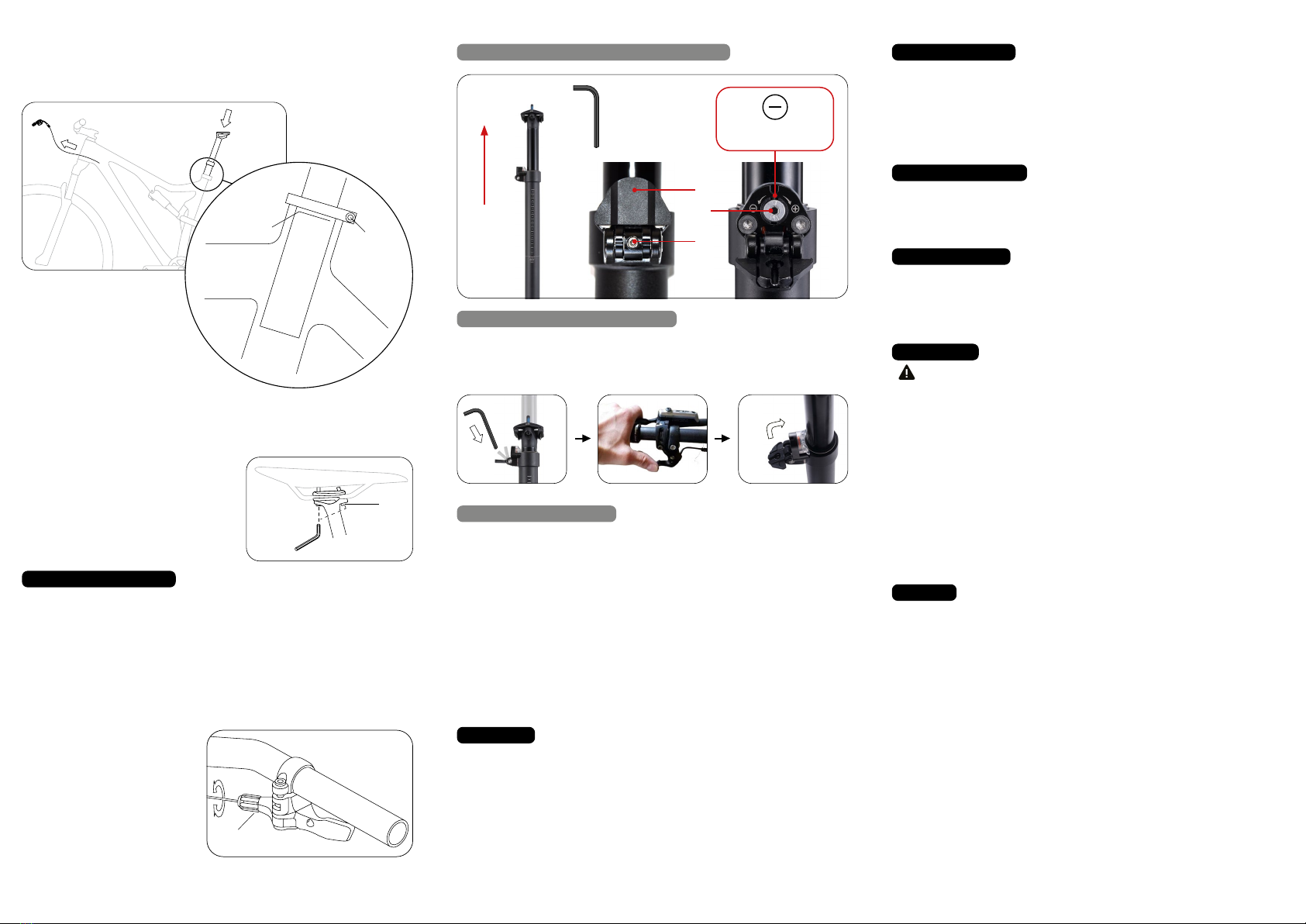
EXTEND THE SEAT POST COMPLETELY (FACTORY SETTING)
A − EXTEND ADJUSTMENT RANGE COMPLETELY
B − LIMIT ADJUSTMENT RANGE
STEP 1: Loosen screw Bwith a 2.5mm Allen key and open flap A
STEP 2: Press the remote lever to release the dropper.
STEP 3: Close flap Aand tighten the screw Bwith Allen key (2.5mm)
STEP 1: Push the remote lever to release the dropper and use the rider‘s weight to lower
the seatpost to the desired end position.
STEP 2: Loosen screw Bwith a 2.5mm Allen key and open flap A
STEP 3: Use an Allen key (2.5mm) to turn the screw Cto the left (–) until the orange rope
stop moving. (This can be observed through the viewing window).
STEP 4: Close flap Aand tighten the screw Bwith Allen key (2.5mm)
1 2 3
Other Merida Bicycle Accessories manuals


Popular Bicycle Accessories manuals by other brands


Specialized
Specialized Elite CylcoComputer user manual

Sigma
Sigma BC 16.16 manual

Playcore
Playcore Dero Setbacks installation instructions

VDO Cyclecomputing
VDO Cyclecomputing x3dw instruction manual

Cateye
Cateye RAPID X2 manual

buratti meccanica
buratti meccanica Clorofilla Trail Use and maintenance manual


