Merit StabiliT MX User manual

StabiliT®MX
Vertebral Augmentation
System
(For use with StabiliT®Bone Cement)
1
StabiliT®MX Vertebral Augmentation System
(For use with StabiliT®Bone Cement)
Instructions for Use (English) (EN)
Important Information –Please Read Before Use
CAUTION: Federal law (USA) restricts this device to sale by or on the order of a physician.
INDICATIONS
The StabiliT®MX Vertebral Augmentation System is intended for percutaneous delivery of
StabiliT® Bone Cement. The StabiliT® Bone Cement is indicated for the treatment of pathological
fractures of the vertebrae using a vertebroplasty or kyphoplasty procedure. Painful vertebral
compression fractures may result from osteoporosis, benign lesions (hemangioma), and
malignant lesions (metastatic cancers, myeloma).
The VertecoR®MidLine Cement Staging Osteotome, VertecoR®MidLine Osteotome (MLO),
VertecoR®StraightLine Cement Staging Osteotome 3.0-11.5 and VertecoR®StraightLine
Cement Staging Osteotome 3.0 (SLO) are intended for scraping or coring of bone in the spine.
DESCRIPTION
The StabiliT MX Vertebral Augmentation System is a system for the controlled delivery of
StabiliT Bone Cement in the treatment of vertebral compression fractures. The StabiliT MX
Vertebral Augmentation System consists of up to eight (8) components (Figure 1).
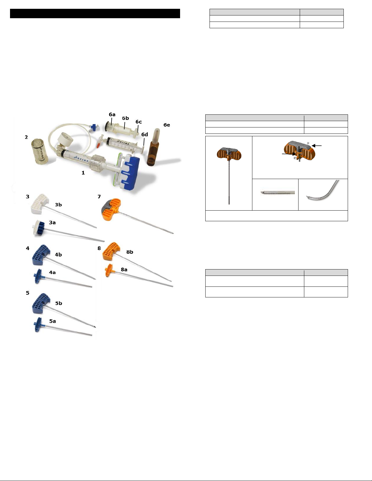
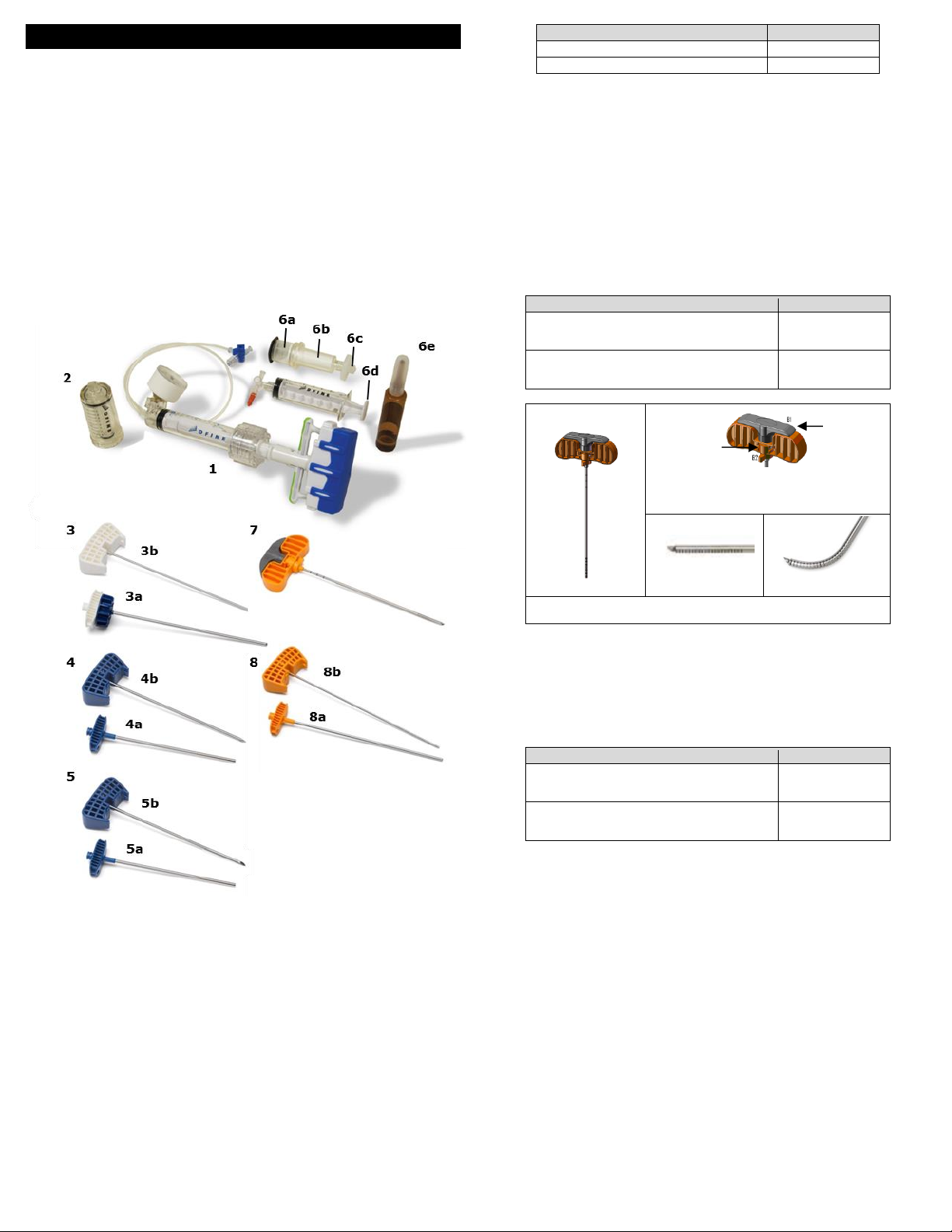
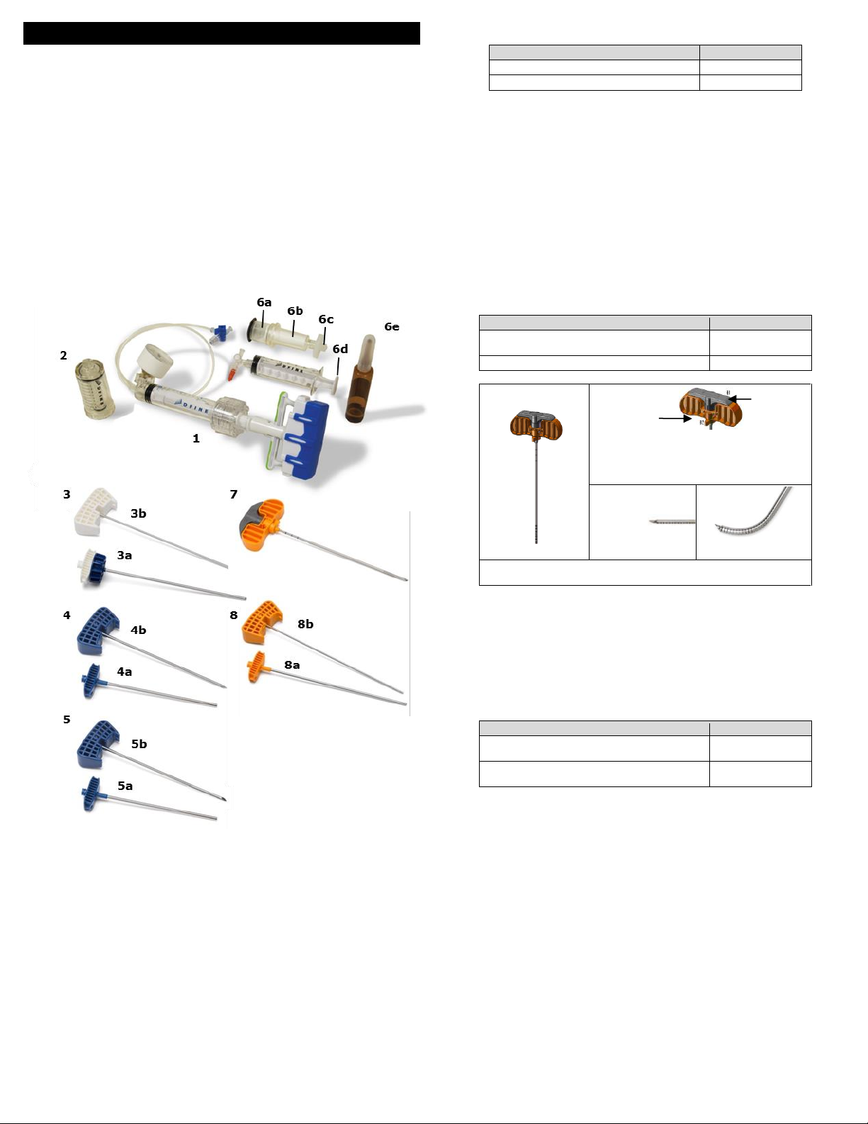
Figure 1. StabiliT MX Vertebral Augmentation System
StabiliT Delivery Syringe (#1) - Used for delivering bone cement into the vertebral body.
StabiliT Delivery Instruments (#2, 3, 4) - Used to provide access to the vertebral body and
facilitate delivery of PMMA bone cement in orthopedic procedures including vertebroplasty or
kyphoplasty procedures.
oMaster Syringe (#2)
oLocking Delivery Cannula (LDC) (#3)
Cannula (3a)
Stylet (3b)
oStabiliT Introducer with diamond tip stylet (#4) - The StabiliT Introducer is used for
percutaneous bone access. The device is packaged with a diamond tip stylet and
cannula. The Introducer cannula is 3.6mm in outer diameter. See the chart below for
the device length.
Cannula (4a)
Stylet (4b)
StabiliT Introducer with bevel tip stylet (#5) in some kit configurations (see product label for
details) –The StabiliT Introducer with bevel tip is used for percutaneous bone access. The
device is packaged with a bevel tip stylet and cannula. The Introducer cannula is 3.6 mm in
outer diameter. See the chart below for the device length.
Cannula (5a)
Stylet (5b)
Device
Working Length
StabiliT Introducer 3.6-11.5
11 cm
StabiliT Introducer 3.6
13 cm
StabiliT Bone Cement and Saturate Mixing System (#6) -
oThe StabiliT Bone Cement is indicated for the treatment of pathological fractures of
the vertebrae using a vertebroplasty or kyphoplasty procedure. Painful vertebral
compression fractures may result from osteoporosis, benign lesions (hemangioma),
and malignant lesions (metastatic cancers, myeloma).
oThe Saturate Mixing System is intended for mixing of StabiliT Bone Cement.
Funnel (#6a)
Cement Syringe (#6b)
Filter (#6c)
Locking syringe (#6d)
Monomer (#6e)
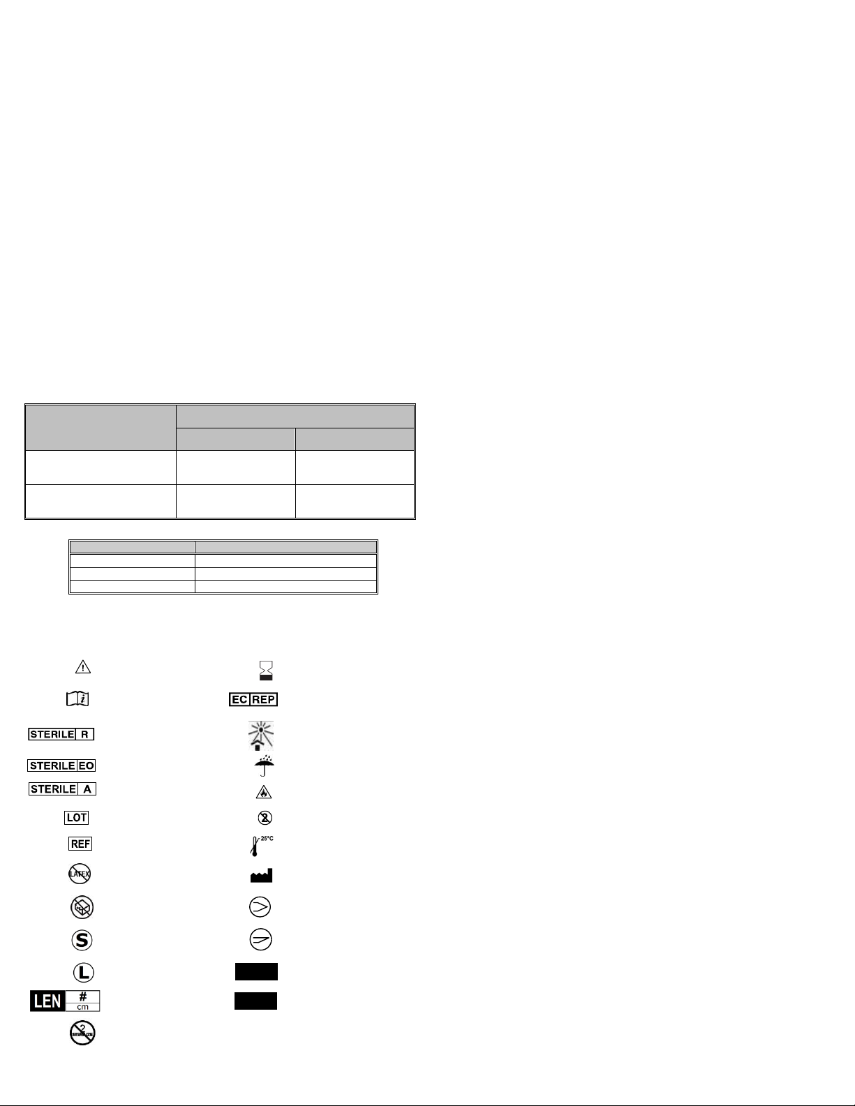
VertecoR MidLine Cement Staging Osteotome (MLO) (#7) –The MLO is a sterile single use
Osteotome device for scraping or coring of bone to create an area in which cement delivery
can be initiated in the treatment of vertebral compression fractures. It is to be used with the
StabiliT Introducer. The shaft is 3.0 mm in outer diameter. See the chart below for the
working lengths.
Device
Working Length
MidLine Cement Staging Osteotome 3.0-11.5
14.5 cm
MidLine Cement Staging Osteotome 3.0
16.5 cm
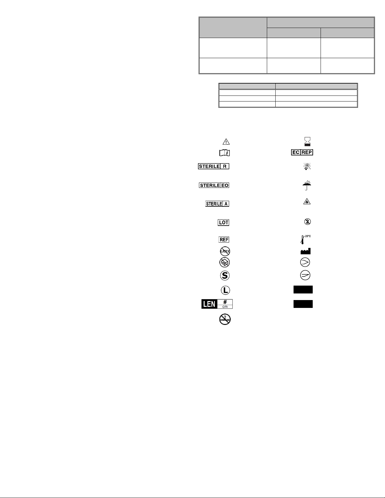
A. MLO
B1. Deployment Handle is the thin rotating
portion of MLO Handle. B2 Directional arrow
points in direction of the articulating tip
C. Articulating Tip
Un-Deployed
D. Articulating Tip
Deployed
The MLO (A) has a Handle (B) that contains a rotating Deployment
Handle that deploys the Articulating Tip (C, D).
VertecoR StraightLine Cement Staging Osteotome (SLO) (#8) in some kit configurations
(see product label for details) –The SLO is a sterile single use osteotome device for scraping
or coring of bone to create an area in which cement delivery can be initiated in the
treatment of vertebral compression fractures and obtain a biopsy. It is packaged with a
blunt tip stylet. It is to be used with the StabiliT Introducer. The shaft is 3.0 mm in outer
diameter. See the chart below for working lengths.
Cannula (8a)
Stylet (8b)
Device
Working Length
VertecoR StraightLine Cement Staging
Osteotome 3.0-11.5
13.5 cm
VertecoR StraightLine Cement Staging
Osteotome 3.0
15.5 cm
HOW SUPPLIED
All components are provided sterile. These devices are intended for single use only. DO NOT
re-sterilize and/or reuse. DO NOT use if package is open or damaged and notify the
manufacturer.
CONTRAINDICATIONS
The use of this product is contraindicated in patients with coagulation disorders, or with
severe pulmonary insufficiency.
The use of this product is contraindicated in patients with a compromise in the posterior
column of the vertebral body or the walls of the pedicles.
The use of PMMA bone cement is contraindicated in the presence of active or incompletely
treated infection at the site where the bone cement is to be applied.
This product should not be used in patients with sensitivity to any of the components of the
PMMA bone cement.
WARNINGS
Thoroughly read the IFUs for each device including the StabiliT Bone Cement and Saturate
Mixing System, (if packaged separately or along with this IFU) before use. The IFU must be
followed to perform a procedure using the StabiliT MX Vertebral Augmentation System.
For safe and effective use, this device should only be used by qualified physicians with
training in the clinical procedure in which it is being used. The physician should have specific
training, experience, and thorough familiarity with the use and application of this product.
Always use fluoroscopic guidance with radiographic equipment that provides high quality
imaging to avoid patient injury. Use appropriate imaging techniques to confirm correct
Working Cannula placement (before and during advancement and after removal), absence
of damage to surrounding structures, and appropriate location of delivered bone cement.
Imaging, such as venography, can be used to assess the ability of the vertebra to contain
the delivered bone cement.
It is essential to maintain strict sterile technique during the procedure and during all phases
of handling this product.
Precise Working Cannula placement is required for this procedure. Incorrect device
placement could result in patient injury.
The Working Cannula (part of the StabiliT Introducer) is not intended for delivering bone
cement. Always use the LDC to deliver bone cement to the vertebral body.

2
The Introducer Stylet must be in place inside the Working Cannula during use (e.g.,
insertion, removal, manipulation).
Removal of the Working Cannula must be performed by rotation and axial motion. DO NOT
bend the cannula sideways, patient injury may occur.
Dispose of used product per local, state and federal blood borne pathogen controls including
biohazard sharps container and disposal procedures.
DO NOT use if package is opened or damaged. All devices are provided sterile. All devices
are sterilized using gamma radiation. These devices are intended for single use only. DO
NOT re-sterilizer re-use. Reconditioning, refurbishing, repair, modification, or re-sterilization
of the device(s) to enable further use is expressly prohibited, as it may result in patient
injury including loss of function and/or infection.
For devices penetrating bone, DO NOT use if dense bone, including traumatic fractures, is
encountered. Device damage resulting in patient injury may occur. Breakage of the device
may require intervention or retrieval.
DO NOT use the StraightLine Osteotome or MidLine Osteotome in fractures due to pararenal
or prostatic cancer metastasis of the spine.
DO NOT use the MidLine Osteotome to scrape or core bone in more than one vertebra.
PRECAUTIONS
Examine all packaging prior to opening. DO NOT use device if damaged or the sterile
packaging is breached. Contact the manufacturer if package is opened or damaged.
Use the device prior to the Use By Date noted on the device packaging.
Wear safety glasses or a face shield when delivering the bone cement.
Ensure that all luer-lock connectors are tightened securely. Improperly secured connections
could result in disconnection during injection.
DO NOT insert the StraightLine Osteotome into the Working Cannula if the Stylet is still
attached to the StraightLine Osteotome, as it may result in inadequate coring of the bone.
Exercise caution in cases involving extensive vertebral destruction and significant vertebral
collapse (i.e., the vertebral body is less than 1/3 of its original height). Such cases may lead
to a technically difficult procedure.
ADVERSE EVENTS
Serious adverse events, some with fatal outcome, associated with the use of
polymethylmethacrylate (PMMA) include:
Myocardial infarction
Cardiac arrest
Cerebrovascular accident
Pulmonary embolism
Anaphylaxis
Diffusion of the bone cement outside the vertebral body: in the peripheral veins
(pulmonary embolism), in the epidural plexus (myelopathy, radiculopathy), in the
intervertebral disc
The most frequent adverse reactions reported with PMMA are:
Transitory fall in blood pressure
Thrombophlebitis
Hemorrhage and hematoma
Superficial or deep wound infection
Bursitis
Short-term cardiac irregularities
Heterotopic bone formation
Other potential adverse events reported for PMMA include:
Pyrexia
Hematuria
Dysuria
Bladder fistula
Transitory worsening of pain due to heat released during polymerization
Nerve entrapment and dysphasia due to extrusion of the bone cement beyond its
intended application
Adhesions and stricture of the ileum due to heat released during polymerization
Potential adverse events associated with kyphoplasty or vertebroplasty include:
Pneumonia
Intercostal neuralgia
Collapse of a vertebra adjacent to the one injected, due to an osteoporotic disease
Pneumothorax
Extravasation of bone cement into soft tissue
Fracture of a pedicle
Rib fracture in patients with diffuse osteopenia, especially during thoracic kyphoplasty
procedures, due to the significant downward force exerted during Working Cannula
insertion
Compression of the spinal cord with paralysis or loss of feeling
Adverse events potentially associated with use of the StabiliT Introducer, MidLine Osteotome
or StraightLine Osteotomes include:
Nerve injury including puncture of the cord or nerve roots potentially resulting in
radiculopathy, paresis or paralysis
Pulmonary embolism
Hemothorax or pneumothorax
Infection, including deep or superficial wound infection
Unintended puncture wounds including vascular puncture and dural tear
Hemorrhage
Hematoma
Pain
PREPARATION AND USE
1) Check packaging for damage prior to placing contents in sterile field.
2) Remove product from package using standard sterile technique.
3) Check all components for damage. If the pressure gauge needle on the StabiliT Delivery
Syringe is resting outside the “0” box, do not use.
4) Mix bone cement per the StabiliT Bone Cement and Saturate Mixing System IFU.
5) Access the vertebral body using the StabiliT Introducer.
a) Under fluoroscopic guidance direct the StabiliT Introducer down the pedicle of the
vertebral body, while checking A/P lateral images to confirm proper device
placement.
b) Once the StabiliT Introducer is positioned in the vertebral body, remove the Stylet
with a counterclockwise turn, leaving the Working Cannula in place.
6) Create an access channel and a cement staging area to stage bone cement delivery
using the SLO and/or the MLO.
WARNING: Use imaging guidance and follow the IFU to avoid patient injury.
a) Use the SLO to create an access channel and a cement staging area in the bone:
i) Remove the Stylet from the SLO and set aside prior to inserting the SLO in
the Working Cannula.
ii) Remove all instrumentation from the Working Cannula.
iii) Using imaging guidance, advance the SLO through the Working Cannula,
bring it into contact with bone and verify placement of the tip of the SLO at
the intended location. The Introducer/SLO stop limits the SLO shaft to
extend 15 mm beyond the distal end of the Working Cannula. Always verify
placement under imaging guidance.
iv) Using imaging guidance, advance the tip of the SLO to the desired location
to carefully scrape or core the bone.
Caution: The location of the Working Cannula in the vertebra should be
monitored before and during advancement of the SLO.
v) Completely seat the SLO against the Working Cannula to completely create
the cement staging space. This may require retraction of the Working
Cannula.
vi) When scraping or coring is complete, using imaging guidance, remove the
SLO from the Working Cannula.
b) Use the MLO to create an access channel and a cement staging area in the bone:
i) The Articulating Tip is the distal portion of the MLO, the directional arrow
points in the direction of the articulating tip bending.
ii) The Deployment Handle is the rotating portion of the MLO Handle.
(1) Turning the Deployment Handle 1/2 turn clockwise will cause the
Articulating Tip to Deploy (fully bend).
(2) Turning the Deployment Handle counter-clockwise will cause the
Articulating Tip to Un-Deploy (straighten).
(3) Do not deploy the Deployment Handle greater than 1/2 turn counter
clockwise.
iii) Ensure the Articulating Tip is fully extended in the straight position prior to
insertion into the Working Cannula.
iv) Remove the stylet from the Working Cannula.
v) Insert the MLO into the Working Cannula until the first laser mark on the
shaft is even with the proximal end of the luer on the Working Cannula.
Confirm by image guidance that the distal end of the MLO is at the distal end
of the Working Cannula before proceeding. When fully inserted into Working
Cannula, the shaft extends approximately 26mm beyond the distal end of
the Working Cannula.
vi) As the Articulating Tip exits the Working Cannula turn the Deployment
Handle to bend the Articulating Tip in the direction of the arrow on the MLO
Handle.
vii) The MLO can be advanced to the desired position using image guidance.
viii) Care should be taken at all times to NEVER strike the arms of the
Deployment Handle, especially when rotated from its starting position.
ix) Using image guidance (and stabilizing the Working Cannula), the MLO can
be carefully withdrawn and advanced multiple times to scrape or core bone
until the desired cavity (size and location) is created.
x) When the Articulating Tip is substantially deployed, the MLO should not be
rotated.
(1) The rotation limiting mechanism will slip if the large handle is rotated
while the Articulating Tip is substantially articulated.
Caution: The location of the Working Cannula in the vertebra should
be monitored before, and during advancement of the MLO through the
Working Cannula.
xi) When cavity creation is complete, using imaging guidance un-deploy the
Articulating Tip and return the Deployment Handle to its starting position.
Caution: Un-Deployment of the Articulating Tip should be done slowly and
under imaging guidance while carefully monitoring the position of the tip of
the device. Un-Deploy the device by turning the Deployment Handle counter
clockwise.
xii) Under imaging guidance, remove the MLO from the StabiliT Introducer’s
Working Cannula.
xiii) The location of the StabiliT Introducer Working Cannula in the vertebra
should be monitored and adjusted if necessary after removal of the MLO.
7) Prepare the StabiliT Delivery Syringe.
a) Remove stopcock from StabiliT Delivery Syringe packaging.
b) Connect the StabiliT Delivery Syringe extension tube to the female connector on
the stopcock (opposite from the male connector).
c) Ensure the male port on the stopcock is set to the closed position.
d) Advance the plunger with enough force to completely remove any air present in
the syringe.
e) Submerge the stopcock in sterile water (or saline).
f) Squeeze the trigger on the StabiliT Delivery Syringe and pull back the handle to fill
the Syringe with fluid. Do so until the entire Syringe is filled.
g) Invert the StabiliT Delivery Syringe, squeeze the trigger, and advance the plunger
to remove any remaining air in the syringe and extension tube.
h) Squeeze the trigger on the StabiliT Delivery Syringe and pull back fully to aspirate
with sterile water (or saline).
Caution: Inspect the StabiliT Delivery Syringe tubing and stopcock to ensure that
there is no air in the system.
8) Assemble system components
a) One minute prior to bone cement delivery (see Table 1) remove the Filter and
Funnel Assembly. Clean the Cement Syringe of excess bone cement and
completely thread the Cement Syringe into the Locking Delivery Cannula.
b) Thread the Master Syringe onto the Cement Syringe.
Caution: Ensure Master Syringe is FULLY threaded onto Cement Syringe before
proceeding. Not doing so can cause user injury or device malfunction.
c) Attach the StabiliT Delivery Syringe to the Master Syringe. Securely connect the
luer of the Master Syringe to the stopcock at the end of the StabiliT Delivery
Syringe extension tube.
Caution: Do not begin bone cement delivery until saturation and preparation time
is complete (see Table 1).
3
9) Cement delivery
a) Confirm that the StabiliT Delivery Syringe trigger is released to ensure that the
plunger is locked in position.
b) Prime the LDC with bone cement by rotating the StabiliT Delivery Syringe handle in
the CLOCKWISE direction. Once bone cement exits LDC tip, stop cement flow by
squeezing the trigger on the StabiliT Delivery Syringe. Release trigger to lock the
plunger in the withdrawn position. Wipe LDC tip clean.
c) Under fluoroscopic guidance, stabilize the Working Cannula and insert the LDC until
the rotating wheel contacts the Working Cannula luer. Rotate the LDC wheel to
lock the LDC to the Working Cannula.
d) When prepared to deliver bone cement squeeze the StabiliT Delivery Syringe
trigger and push the handle forward until resistance is met and release the trigger.
Under fluoroscopic guidance, deliver bone cement by rotating the handle in the
CLOCKWISE direction.
e) To stop bone cement delivery, squeeze the trigger on the StabiliT Delivery Syringe.
Release trigger to lock the plunger in the withdrawn position. To re-engage,
squeeze the trigger and push the handle forward until resistance is met, then
release trigger. Continue delivering bone cement by rotating the handle in the
CLOCKWISE direction.
Caution: To protect the threads of the lock release handle, the gauge must
indicate 25 ATM or lower before the quick release mechanism is used to stop flow
and relieve pressure.
Caution: The quick release mechanism will activate (signaled by a clicking sound)
if the operator exceeds the maximum pressure for the StabiliT Delivery Syringe.
Once this has occurred, the quick release mechanism may disengage at lower
pressures during subsequent attempts to increase pressure.
Caution: Following completion of bone cement delivery, remove the LDC from
the Working Cannula within 1 minute and immediately insert and lock the Stylet in
the Working Cannula. If no additional bone cement delivery is required, remove
Introducer (Cannula with Stylet).
Warning: Removal of the Working Cannula should only be performed after
insertion of the Stylet by rotation and axial motion. DO NOT bend Working Cannula
sideways, patient injury may occur.
Table 1: Timing of Various Activities at Different Ambient Temperatures
Activity
Approximate Cumulative Time From
Initiation of Saturation (minutes)
@ 18-19 °C
(65-67 °F)
@ 20-23 °C
(68-74 °F)
Bone Cement Saturation and
Preparation
(See Bone Cement IFU)
0-10 minutes
0-5 minutes
Bone Cement Delivery
10-45 minutes
(35 minutes working
time)
5-40 minutes
(35 minutes working
time)
Table 2: Effect of Ambient Temperature on Cement
Temperature ºF (ºC)
Minimum Setting Time (minutes)
81 (27)
35
73 (23)
51
66 (19)
82
STORAGE & HANDLING
Handle with care. Store in original packaging in a clean, cool, and dry location. Avoid exposure
to temperature and humidity extremes.
SYMBOL GLOSSARY
Caution
Use By
Consult Instructions For
Use
Authorized
Representative in the
European Community
Sterilized using
Irradiation
Keep away from sunlight
Sterilized using Ethylene
Oxide
Keep away from moisture
Sterilized using Asceptic
Processing Techniques
Flammable
Lot Number
Single Use Device,
DO NOT REUSE
Catalog Number
Store below 25°C
No Latex
Manufacturer
Do not use if package is
opened or damaged
Diamond tip
Short
Bevel Tip
Long
Cannula Gauge
Device Length in
Centimeters
Introducer Gauge/Locking
Delivery Cannula Gauge
Do not Resterilize
QTY:
Quantity
# / # G
# G
4
Sustav za povećavanje kralježaka StabiliT®MX
(za uporabu s koštanim cementom StabiliT®)
Upute za uporabu (hrvatski) (HR)
Važne informacije – pročitati prije uporabe
OPREZ: Prema saveznom zakonu SAD-a ovaj se uređaj smije prodavati
isključivo putem liječnika ili na liječnički recept.
INDIKACIJE
Sustav za povećavanje kralježaka StabiliT®MX je namijenjen za perkutano dopremanje
koštanog cementa StabiliT®.Koštani cement StabiliT® indiciran je za liječenje patoloških
prijeloma kralježnice tehnikom vertebroplastike ili kifoplastike. Bolni kompresijski prijelomi
kralježaka mogu nastati uslijed osteoporoze, benignih lezija (hemangioma) i
malignih lezija (metastatskih karcinoma, mijeloma).
Srednjelinijski osteotom za cementiranje VertecoR®, srednjelinijski osteotom VertecoR®
(MidLine Osteotome, MLO), ravnolinijski osteotom za cementiranje VertecoR®3,0-11,5 i
ravnolinijski osteotom za cementiranje VertecoR®3,0 (StraightLine Osteotome, SLO)
namijenjeni su za struganje ili otvrdnjavanje u kralježnici.
OPIS
Sustav za povećavanje kralježaka StabiliT MX je sustav za kontrolirano dopremanje koštanog
cementa StabiliT u liječenju kompresijskih prijeloma kralježaka. Sustav za povećavanje
kralježaka StabiliT MX sadrži do osam (8) sastavnica (Slika 1).
Slika 1. StabiliT MX sustav za povećavanje kralježaka
Štrcaljka za dopremanje StabiliT (1) – koristi se za dopremanje koštanog cementa u tijelo
kralješka.
Instrumenti za dopremanje StabiliT (2, 3, 4) –koriste se da osiguraju pristup tijelu kralješka
i dopreme PMMA koštani cement u ortopedskim zahvatima, uključujući i vertebroplastiku ili
kifoplastiku.
oGlavna štrcaljka (2)
oZaključavajuća kanila za dopremanje (3)
Kanila (3a)
Stilet (3b)
oUvodnica StabiliT sa stiletom dijamantnog vrha (4) –uvodnica StabiliT koristi se za
perkutani pristup kosti. Uređaj je pakiran sa stiletom dijamantnog vrha i kanilom.
Vanjski promjer kanile uvodnice iznosi 3,6 mm. Za duljinu uređaja pogledajte donji
dijagram.
Kanila (4a)
Stilet (4b)
Uvodnica StabiliT sa stiletom kosog vrha (5) u nekim konfiguracijama kompleta (za
pojedinosti pogledati oznaku na proizvodu) –uvodnica StabiliT s kosim vrhom koristi se za
perkutani pristup kosti. Uređaj je pakiran sa stiletom kosog vrha i kanilom. Vanjski promjer
kanile uvodnice iznosi 3,6 mm. Za duljinu uređaja pogledajte donji dijagram.
Kanila (5a)
Stilet (5b)
Uređaj
Radna duljina
Uvodnica StabiliT 3,6-11,5
11 cm
Uvodnica StabiliT 3,6
13 cm
Koštani cement StabiliT i sustav za miješanje cementa (6):
oKoštani cement StabiliT indiciran je za liječenje patoloških prijeloma kralježnice
tehnikom vertebroplastike ili kifoplastikom. Bolni kompresijski prijelomi kralježaka
mogu nastati uslijed osteoporoze, benignih lezija (hemangioma) i malignih lezija
(metastatskih karcinoma, mijeloma).
oSustav za miješanje cementa namijenjen je miješanju koštanog cementa StabiliT.
Lijevak (6a)
Štrcaljka za cement (6b)
Filtar (6c)
Štrcaljka za zatvaranje (6d)
Monomer (6e)
Srednjelinijski osteotom za cementiranje VertecoR (MLO) (7) –MLO je sterilni osteotom za
struganje ili utvrđivanje kosti kako bi se napravilo područje u koje se može započeti
dostavljati cement u liječenju kompresivnih prijeloma kralježnice. Mora se koristiti uz
uvodnicu StabiliT. Vanjski promjer osovine iznosi 3,0 mm. Za radne duljine pogledajte
dijagram niže.
Uređaj
Radna duljina
Srednjelinijski osteotom za cementiranje 3,0-
11,5
14,5 cm
Srednjelinijski osteotom za cementiranje 3,0
16,5 cm
A. MLO
B1. Ručka za okretanje je u tankom
rotirajućem dijelu ručke MLO. B2
usmjeravajuća strelica koja pokazuje smjer
uzglobljenog vrha
C. Uzglobljeni vrh
isključen
C. Uzglobljeni vrh
uključen
MLO (A) ima ručku (B) koja sadrži ručicu za okretanje koja
uključuje uzglobljeni vrh (C, D).
Ravnolinijski osteotom za cementiranje VertecoR (SLO) (8) u nekim konfiguracijama
kompleta (za pojedinosti pogledati oznaku na proizvodu) –SLO je sterilni osteotom za
struganje ili utvrđivanje kosti kako bi se napravilo područje u koje se može započeti
dostavljati cement u liječenju kompresivnih prijeloma kralježnice te obaviti biopsija.
Zapakiran je sa stiletom tupog vrha. Mora se koristiti uz uvodnicu StabiliT. Vanjski promjer
osovine iznosi 3,0 mm. Za radne duljine pogledajte dijagram niže.
Kanila (8a)
Stilet (8b)
Uređaj
Radna duljina
Ravnolinijski osteotom za cementiranje
VertecoR 3,0-11,5
13,5 cm
Ravnolinijski osteotom za cementiranje
VertecoR 3,0
15,5 cm
PAKIRANJE
Sve sastavnice se isporučuju sterilne. Ovi uređaji su namijenjeni samo za jednokratnu
uporabu. NEMOJTE ponovno sterilizirati ni ponovno upotrebljavati. NEMOJTE koristiti ako je
pakiranje otvoreno ili oštećeno te obavijestite proizvođača.
KONTRAINDIKACIJE
Uporaba ovog proizvoda je kontraindicirana kod bolesnika s poremećajima zgrušavanja ili s
teškom plućnom insuficijencijom.
Uporaba ovog proizvoda je kontraindicirana kod bolesnika s ugroženom stražnjim dijelom
tijela kralješka ili ugroženim zidovima pedikula.
Uporaba PMMA koštanog cementa je kontraindicirana u prisutnosti aktivne ili nepotpuno
izliječene infekcije na mjestu gdje bi se koštani cement trebao primijeniti.
Proizvod se ne smije koristiti ni u bolesnika s preosjetljivošću na bilo koju od komponenti
PMMA koštanog cementa.
UPOZORENJA
Prije uporabe temeljito proučite upute za svaki od uređaja, uključujući i koštani cement
StabiliT i sustav za miješanje cementa (ako su pakirane posebno ili zajedno s ovim
uputama). Moraju se pratiti upute za uporabu kako bi se postupak proveo pomoću sustava
za povećavanje kralježaka StabiliT MX:
Za sigurnu i učinkovitu uporabu, ovaj uređaj smije koristiti samo kvalificirani liječnik koji je
obučen za klinički postupak u kojem se uređaj koristi. Liječnik mora imati određen trening,
iskustvo i temeljito poznavanje uporabe i primjene ovog proizvoda.
Uvijek koristite fluoroskopsko navođenje s radiografskom opremom koja daje prikaze visoke
kvalitete kako biste izbjegli ozljedu bolesnika. Koristite odgovarajuće tehnike oslikavanja
kako biste potvrdili ispravan položaj radne kanile (prije i tijekom napredovanja i nakon
uklanjanja), da nema oštećenja okolnih struktura i odgovarajući položaj dopremljenog
koštanog cementa. Tehnike oslikavanja, kao što je venografija, mogu se koristiti za
procjenu sposobnosti kralješka da zadrži dopremljeneni koštani cement.
Tijekom postupka i svih faza rukovanja proizvodom nužno je koristiti potpuno sterilan
postupak.
Za ovaj postupak potrebno je precizno namjestiti radnu kanilu. Neispravno namještanje
uređaja može dovesti do ozljede bolesnika.

5
Radna kanila (dio uvodnice StabiliT) nije namijenjena za dopremanje koštanog cementa.
Za dopremanje cementa u tijelo kralješka uvijek koristite zaključavajuću kanilu za
dopremanje.
Stilet uvodnice mora tijekom uporabe biti unutar radne kanile (npr. umetanje, uklanjanje,
rukovanje).
Uklanjanje radne kanile se mora izvesti zakretanjem i aksijalnim pokretima. NEMOJTE
savijati kanilu u stranu, to može dovesti do ozljede bolesnika.
Korišteni proizvod odložite u otpad prema lokalnim, državnim i saveznim mjerama za
kontrolu patogena koji se prenose krvlju, uključujući naputke za ambalažu i odlaganje
biološki opasnih oštrih predmeta.
NEMOJTE koristiti proizvod ako je pakiranje otvoreno ili oštećeno. Svi uređaji se isporučuju
sterilni. Svi uređaji su sterilizirani gama-zračenjem. Ovi uređaji su namijenjeni samo za
jednokratnu uporabu. NEMOJTE ponovno sterilizirati. Izričito su zabranjeni obnavljanje,
popravljanje, mijenjanje i ponovna sterilizacija uređaja kojom bi se omogućila daljnja
upotreba jer to može prouzročiti ozljede bolesnika, uključujući i gubitak funkcije i/ili infekciju.
NEMOJTE koristiti uređaje koji probijaju kost ako naiđete na kost velike gustoće, uključujući i
traumatske prijelome. To može dovesti do oštećenja uređaja te ozljede bolesnika. Lom
uređaja može zahtijevati intervenciju ili popravak.
NE koristite ravnolinijski osteotom ili srednjelinijski osteotom u prijelomima zbog
metastaziranja pararenalnog karcinoma ili karcinoma prostate u kralježnicu.
NE koristite srednjelinijski osteotom za struganje ili utvrđivanje u više od jednog kralješka.
MJERE OPREZA
Prije otvaranja pregledajte sva pakiranja. NEMOJTE koristiti uređaj ako je oštećen ili je
pakiranje otvoreno. Obratite se proizvođaču ako je pakiranje otvoreno ili oštećeno.
Uređaj koristite prije isteka roka trajanja označenog na pakiranju.
Nosite zaštitne naočale ili vizir prilikom dopremanja cementa.
Osigurajte da su sve luer lock spojnice sigurno pričvršćene. Neispravno osigurane spojnice
se mogu razdvojiti tijekom ubrizgavanja.
NEMOJTE stavljati ravnolinijski osteotom u radnu kanilu ako je stilet još uvijek pričvršćen na
ravnolinijski osteotom jer to može dovesti do neodgovarajućeg otvrdnjavanja kosti.
Budite osobito oprezni u slučajevima opsežnog oštećenja kralježaka i znatnog kolapsa
kralježaka (tj. tijelo kralješka je manje od 1/3 svoje prvotne visine). U tim slučajevima
zahvat može biti tehnički zahtjevan.
NUSPOJAVE
Ozbiljne nuspojave povezane s upotrebom polimetilmetakrilata (PMMA), neke sa smrtnim
ishodom, obuhvaćaju sljedeće:
infarkt miokarda
srčani zastoj
cerebrovaskularni incident
plućna embolija
anafilaktički šok
istjecanje koštanog cementa izvan tijela kralješka: u periferne vene (plućna embolija),
epiduralni pleksus (mijelopatija, radikulopatija), međukralježnički disk
Najčešće zabilježene nuspojave primjene PMMA su sljedeće:
prolazni pad krvnog tlaka
tromboflebitis
krvarenje i hematomi
površinske ili duboke infekcije rana
burzitis
kratkoročne nepravilnosti u radu srca
heterotopično okoštavanje
Ostali zabilježeni potencijalno štetni događaji vezani uz PMMA obuhvaćaju sljedeće:
pireksiju
hematuriju
dizuriju
fistule na mjehuru
prolazno pojačanje boli zbog topline koja se oslobađa tijekom polimerizacije
uklještenje živca i disfaziju zbog izbočenja koštanog cementa izvan željenog mjesta
primjene
adhezije i strikture ileuma zbog topline koja se oslobađa tijekom polimerizacije
Potencijalno štetni događaji povezani s kifoplastikom ili vertebroplastikom obuhvaćaju
sljedeće:
upalu pluća
interkostalnu neuralgiju
kolaps susjednog kralješka onome koji je injekciran, uslijed osteoporoze
pneumotoraks
izljev koštanog cementa u meko tkivo
frakturu pedikule
prijelom rebara kod bolesnika s difuznom osteopenijom, osobito tijekom postupaka
torakalne kifoplastike, uslijed znatne sile prema dolje koja se primjenjuje tijekom
umetanja radne kanile
kompresija kralježničke moždine s paralizom ili gubitkom osjeta
Nuspojave koje mogu biti povezane s korištenjem uvodnice StabiliT srednjelinijskog
osteotoma ili ravnolinijskog osteotoma obuhvaćaju sljedeće:
ozljedu živca, uključujući ubod kralježničke moždine ili korijena živaca koji mogu dovesti
do radikulopatije, pareze ili paralize
plućnu emboliju
hemotoraks ili pneumotoraks
infekciju, uključujući infekciju duboke ili površinske rane
slučajne ubodne ozljede, uključujući vaskularnu punkciju i kidanje dure
krvarenje
hematom
bol
PRIPREMA I UPORABA
1) Provjerite je li pakiranje oštećeno prije no što sadržaj stavite u sterilno polje.
2) Uklonite proizvod iz pakiranja koristeći standardnu sterilnu tehniku.
3) Provjerite jesu li sve sastavnice neoštećene. Ne koristiti ako igla za mjerenje tlaka na
štrcaljki za dopremanje StabiliT leži izvan pravokutnika „0”.
4) Koštani cement miješajte prema uputama za uporabu koštanog cementa StabiliT i
sustava za miješanje cementa.
5) Pomoću uvodnice StabiliT pristupite tijelu kralješka.
a) Uvodnicu StabiliT usmjerite izravno niz pedikul tijela kralješka koristeći
fluoroskopsko navođenje i provjeravajući AP/lateralne prikaze kako biste potvrdili
ispravan položaj uređaja.
b) Jednom kad je uvodnica StabiliT smještena u tijelu kralješka, uklonite stilet
okretanjem u smjeru suprotnom od kazaljke na satu ostavljajući radnu kanilu na
mjestu.
6) Napravite kanal za pristup i područje za cementiranje u kosti radi dopremanja koštanog
cementa pomoću SLO i/ili MLO.
UPOZORENJE: Koristite navo?enje oslikavanjem i pratite upute za uporabu kako biste
izbjegli ozljedu bolesnika.
a) Koristite SLO kako biste napravili kanal za pristup i područje za cementiranje u
kosti:
i) Uklonite stilet sa SLO i odložite ga sa strane prije no što umetnete SLO u
radnu kanilu.
ii) Uklonite sve instrumente iz radne kanile.
iii) Navođeni oslikavanjem, napredujte SLO kroz radnu kanilu, dovedite ga u
kontakt s kosti i potvrdite smještaj vrha SLO na željenom mjestu. Graničnik
na uvodnici/SLO ograničava osovinu SLO da dosegne dalje od 15 mm od
distalnog kraja radne kanile. Uvijek provjerite smještaj uz pomoć navođenja
oslikavanjem.
iv) Navođeni oslikavanjem, napredujte vrhom SLO do željene lokacije kako
biste pažljivo ostrugali ili otvrdnuli kost.
Oprez: Prije i tijekom napredovanja SLO mora se nadzirati položaj radne
kanile u kralješku.
v) Položite u potpunosti SLO o radnu kanilu kako biste do kraja stvorili prostor
za cementiranje. To može zahtijevati povlačenje radne kanile.
vi) Prilikom struganja ili utvrđivanja navođeni oslikavanjem uklonite SLO iz
radne kanile.
b) Koristite MLO kako biste napravili kanal za pristup i područje za cementiranje u
kosti:
i) Uzglobljeni vrh je distalni dio MLO, strelica za usmjeravanje pokazuje u
smjeru savijanja uzglobljenog vrha.
ii) Ručica za okretanje je u rotirajućem dijelu ručke MLO.
(1) Okretanje ručice za uključivanje 1/2 okreta u smjeru kazaljke na satu
dovest će do toga da se uzglobljeni vrh uključi (u potpunosti savije).
(2) Okretanje ručice za savijanje u smjeru obrnutom od kazaljke na satu
dovest će do toga da se uzglobljeni vrh ispravi (izravna).
(3) Ne okrećite ručicu više od 1/2 okreta u smjeru suprotnom od kazaljke
za satu.
iii) Uvjerite se da je uzglobljeni vrh u potpunosti izravnan prije no što ga
umetnete u radnu kanilu.
iv) Uklonite stilet iz radne kanile.
v) Umetnite MLO u radnu kanilu sve dok se prva laserska oznaka na osovini ne
poravna s proksimalnim krajem ulaza na radnoj kanili. Prije no što nastavite,
potvrdite oslikavanjem navođenja da je distalni kraj MLO u distalnom kraju
radne kanile. Kad je u potpunosti umetnuta u radnu kanilu, osovina doseže
približno 26 mm od distalnog kraja radne kanile.
vi) Kad uzglobljeni vrh izađe iz radne kanile, okrenite ručicu kako biste savili
uzglobljeni vrh u smjeru strelice na ručki MLO.
vii) MLO se može postaviti u željeni položaj koristeći navođenje oslikavanjem.
viii) U svakom trenutku treba paziti da se NIKAD ne udare krakovi ručice za
okretanje, osobito kad je okrenuta iz svog početnog položaja.
ix) Koristeći navođenje oslikavanjem (i stabilizirajući radnu kanilu), MLO se
može pažljivo povlačiti i gurati više puta kako bi ostrugao ili otvrdnuo kost
sve dok se ne stvori željena šupljina (veličina i položaj).
x) Kad je uzglobljeni vrh znatno savijen, MLO se ne bi smio okretati.
(1) Mehanizam koji ograničava okretanje će skliznuti ako se velika ručka
okreće dok je uzglobljeni vrh znatno savinut.
Oprez: Prije i tijekom napredovanja MLO kroz radnu kanilu mora se
nadzirati položaj radne kanile u kralješku.
xi) Kad je završeno stvaranje šupljine, koristeći navođenje oslikavanjem
izravnajte uzglobljeni vrh i vratite ručku za okretanje u početni položaj.
Oprez: Vraćanje uzglobljenog vrha u početni položaj mora se provoditi
polagano i pod nadzorom oslikavanjem, pažljivo prateći položaj vrha
uređaja. Vratite uređaj u početni položaj, okrećući ručku za okretanje u
smjeru suprotnom od kazaljke na satu.
xii) Pod nadzorom oslikavanja, uklonite MLO iz radne kanile uvodnice StabiliT.
xiii) Položaj radne kanile uvodnice StabiliT u kralješku mora se nakon uklanjanja
MLO nadzirati i prilagoditi ako je potrebno.
7) Pripremite štrcaljku za dopremanje StabiliT.
a) Uklonite ventil s ambalaže štrcaljke za dopremanje StabiliT.
b) Povežite produžnu cijev štrcaljke za dopremanje StabiliT na ženski priključak
ventila (suprotno od muškog priključka).
c) Osigurajte da muški priključak ventila bude u zatvorenom položaju.
d) Pomaknite klip dovoljnom silom da se ukloni sav zrak prisutan u štrcaljki.
e) Potopite ventil u sterilnu vodu (ili slanu otopinu).
f) Stegnite okidač na štrcaljki za dopremanje StabiliT i povucite ručku unatrag kako
biste štrcaljku napunili tekućinom. Činite to dok se ne napuni cijela štrcaljka.
g) Okrenite štrcaljku za dopremanje StabiliT naopako, stegnite okidač te pomičite klip
prema naprijed kako biste uklonili sav preostali zrak iz štrcaljke i produžne cijevi.
h) Stegnite okidač na štrcaljki za dopremanje StabiliT i povucite ručku skroz unatrag
kako biste uvukli sterilnu vodu (ili slanu otopinu).
Oprez:Provjerite cijev štrcaljke za dopremanje StabiliT i ventil kako biste osigurali
da u sustavu više nema zraka.
8) Sklopite sastavnice sustava
a) Jednu minutu prije dopremanja koštanog cementa (pogledajte Tablicu 1) uklonite
sklop filtra i lijevka. Očistite štrcaljku za cement od viška koštanog cementa te
potpuno uvrnite štrcaljku za cement u zaključavajuću kanilu za dopremanje.
b) Navrnite glavnu štrcaljku na štrcaljku za cement.
Oprez: Prije no što nastavite, osigurajte da je glavna štrcaljka U POTPUNOSTI
navrnuta na štrcaljku za cement. Ako to ne učinite, može doći do ozljede ili kvara
uređaja.
6
c) Pričvrstite štrcaljku za dopremanje StabiliT na glavnu štrcaljku. Čvrsto spojte luer
spojnicu glavne štrcaljke s ventilom na kraju produžne cijevi štrcaljke za
dopremanje StabiliT.
Oprez: Ne počinjite dopremanje koštanog cementa dok ne istekne vrijeme
zasićenja i pripreme (pogledajte Tablicu 1).
9) Dopremanje cementa
a) Potvrdite da je okidač štrcaljke za dopremanje StabiliT otpušten kako biste
osigurali da je klip u zaključanu položaju.
b) Napunite zaključavajuću štrcaljku za dopremanje koštanim cementom
zakretanjem ručke štrcaljke za dopremanje StabiliT U SMJERU KAZALJKE NA
SATU. Kada koštani cement napusti vrh zaključavajuće štrcaljke za dopremanje,
prekinite dotok cementa stezanjem okidača štrcaljke za dopremanje StabiliT.
Otpustite okidač kako bi se klip zaključao u uvučenom položaju. Očistite vrh
zaključavajuće štrcaljke za dopremanje.
c) Pod fluoroskopskim nadzorom stabilizirajte radnu kanilu te umećite zaključavajuću
štrcaljku za dopremanje sve dok rotirajući kotač ne dodirne luer spojnicu radne
kanile. Zakrenite kotač da zaključate zaključavajuću štrcaljku za dopremanje u
radnu kanilu.
d) Kad budete spremni za dopremanje koštanog cementa, stegnite okidač štrcaljke
za dopremanje StabiliT i gurnite ručku prema naprijed sve dok ne naiđete na
otpor, a zatim otpustite okidač. Pod fluoroskopskim nadzorom dopremite koštani
cement zakretanjem ručke U SMJERU KAZALJKE NA SATU.
e) Da biste prekinuli dotok koštanog cementa, stegnite okidač štrcaljke za
dopremanje StabiliT. Otpustite okidač kako bi se klip zaključao u uvučenom
položaju. Da biste nastavili, stegnite okidač i gurnite ručku prema naprijed dok ne
naiđete na otpor, a zatim otpustite okidač. Nastavite dopremati koštani cement
zakretanjem ručke U SMJERU KAZALJKE NA SATU.
Oprez: Da biste zaštitili navoje ručke za oslobađanje spojnice, mjerač tlaka mora
pokazivati 25 atmosfera ili manje prije no što se mehanizam za brzo oslobađanje
bude mogao koristiti za zaustavljanje protoka i smanjenje tlaka.
Oprez: Mehanizam za brzo oslobađanje će se aktivirati (uz škljocanje) ako
rukovatelj prekorači maksimalan tlak štrcaljke za dopremanje StabiliT. Nakon
toga, mehanizam za brzo oslobađanje se može razdvojiti pri manjem tlaku tijekom
narednih pokušaja povećanja tlaka.
Oprez: Nakon završetka dopremanja koštanog cementa, uklonite zaključavajuću
štrcaljku za dopremanje iz radne kanile unutar 1 minute i odmah umetnite stilet u
radnu kanilu. Ako nije potrebno daljnje dopremanje koštanog cementa,
uklonite uvodnicu (kanilu sa stiletom).
Upozorenje: Uklanjanje radne kanile se smije izvesti samo nakon uvlačenja
stileta zakretanjem i aksijalnim pokretima. NEMOJTE savijati radnu kanilu u
stranu, to može dovesti do ozljede bolesnika.
Tablica 1: Vremenski redoslijed raznih aktivnosti pri različitim temperaturama okoliša
Aktivnost
Približno kumulativno vrijeme od početka
do zasićenja na 23 °C (minute)
Na 18-19 °C
(65-67 °F)
Na 20-23 °C
(68-74 °F)
Zasićenje i priprema
koštanog cementa
(pogledajte upute za uporabu
koštanog cementa)
0-10 minuta
0-5 minuta
Dopremanje koštanog
cementa
10-45 minuta
(vrijeme rada 35
minuta)
5-40 minuta
(vrijeme rada 35
minuta)
Tablica 2: Utjecaj temperature okoliša na cement
Temperatura ºC (ºF)
Minimalno vrijeme slijeganja
(minute)
27 (81)
35
23 (73)
51
19 (66)
82
ČUVANJE I RUKOVANJE
Oprezno rukovati. Čuvati u originalnom pakiranju na čistom, hladnom i suhom mjestu.
Izbjegavajte izlaganje ekstremnim temperaturama i vlazi.
RJEČNIK SIMBOLA
Oprez
Rok uporabe
Provjerite upute za
uporabu
Ovlašteni predstavnik u
Europskoj zajednici
Sterilizirano zračenjem
(instrumenti za
dopremanje, osteotomi i
uvodnica)
Čuvati dalje od sunčeva
svjetla
Sterilizirano etilen-
oksidom (prah koštanog
cementa i štrcaljka za
dopremanje)
Čuvati od vlage
Sterilizirano filtriranjem
(tekućina koštanog
cementa)
Zapaljivo
Broj serije
Uređaj za jednokratnu
upotrebu, NEMOJTE
PONOVNO KORISTITI
Kataloški broj
Čuvati na temperaturi
manjoj od 25 °C
Ne sadrži lateks
Proizvođač
Ne koristiti ako je
pakiranje otvoreno ili
oštećeno
Dijamantnii vrh
Kratki
Kosi vrh
Dugi
Veličina kanile
Duljina uređaja u
centimetrima
Veličina uvodnika/Veličina
kanile za dostavu na
zaključavanje
Nemojte ponovno
sterilizirati.
QTY:
Količina
# G
# / # G
7
StabiliT®MX Vertebrální augmentační systém
(Pro použití s kostním cementem StabiliT®)
Návod k použití (česky) (CS)
Důležité informace – přečtěte si před použitím
UPOZORNĚNÍ: Federální zákony (USA) omezují prodej tohoto zařízení na lékaře nebo na
lékařský předpis.
INDIKACE
Vertebrální augmentační systém StabiliT®MX je určen pro perkutánní aplikaci kostního
cementu StabiliT® . Kostní cement StabiliT® je určen k léčbě patologických zlomenin obratlů
vertebroplastikou nebo jyfoplastikou. K bolestivým vertebrálním kompresním zlomeninám
může dojít v důsledku osteoporózy, benigních lézí (hemangiom), a maligních lézí (rakovinné
metastázy, myelom).
OsteotomVertecoR®MidLine Cement Staging Osteotome, osteotom VertecoR®MidLine
Osteotome (MLO), osteotom VertecoR®StraightLine Cement Staging Osteotome 3.0-11.5 a
osteotom VertecoR®StraightLine Cement Staging Osteotome 3.0 (SLO) jsou určeny pro
škrábání a vyškrabávání kosti v oblasti páteře.
POPIS
Vertebrální augmentační systém StabiliT MX je systém k řízenému zavedení kostního cementu
StabiliT při léčbě kompresních zlomenin obratlů. Vertebrální augmentační systém StabiliT MX se
skládá až z osmi (8) komponent (obr. 1).
Obrázek 1. Vertebrální augmentační systém StabiliT MX
Aplikační stříkačka StabiliT (č. 1) - používá se pro aplikaci kostního cementu do těla obratle.
Aplikační nástroje StabiliT (č. 2, 3, 4) - používají se pro zajištění přístupu k tělu obratle a pro
usnadnění aplikace kostního cementu PMMA při ortopedických operacích včetně
vertebroplastiky nebo kyfoplastiky.
oHlavní stříkačka (č. 2)
oAplikační kanyla s aretací (LDC) (č. 3)
Kanyla (3a)
Stylet (3b)
oZavaděč StabiliT se styletem s diamantovým hrotem (č. 4) - zavaděč StabiliT se
používá pro perkutánní přístup do kosti. Prostředek je balen se styletem s
diamantovým hrotem a kanylou. Vnější průměr kanyly zavaděče je 3,6 mm. Délka
prostředku je uvedena v tabulce níže.
Kanyla (4a)
Stylet (4b)
Zavaděč StabiliT je v některých konfiguracích soupravy (bližší informace viz označení
produktu) balen se styletem se zkoseným hrotem (č. 5) – zavaděč StabiliT se zkoseným
hrotem se používá pro perkutánní přístup do kosti. Prostředek je balen se styletem se
zkoseným hrotem a kanylou. Vnější průměr kanyly zavaděče je 3,6 mm. Délka prostředku
je uvedena v tabulce níže.
Kanyla (5a)
Stylet (5b)
Prostředek
Pracovní délka
Zavaděč StabiliT 3.6-11.5
11 cm
Zavaděč StabiliT 3.6
13 cm
Kostní cement StabiliT a saturační míchací systém (č. 6) -
oKostní cement StabiliT je určen k léčbě patologických zlomenin obratlů s použitím
vertebroplastiky nebo kyfoplastiky. K bolestivým vertebrálním kompresním
zlomeninám může dojít v důsledku osteoporózy, benigních lézí (hemangiom) a
maligních lézí (rakovinné metastázy, myelom).
oSaturační míchací systém je určen k přípravě směsi kostního cementu StabiliT.
Nálevka (č. 6a)
Stříkačka na cement (č. 6b)
Filtr (č. 6c)
Zamykací stříkačka (č. 6d)
Monomer (č. 6e)
Osteotom VertecoR MidLine Cement Staging (MLO) (č. 7) - MLO je sterilní osteotom k
jednorázovému použití určený ke škrábání nebo vyškrabávání kosti, aby vznikl prostor pro
zahájení aplikace cementu při léčbě kompresních zlomenin obratlů. Je třeba jej používat se
zavaděčem StabiliT. Vnější průměr těla je 3,0 mm. Pracovní délky jsou uvedeny v tabulce
níže.
Prostředek
Pracovní délka
Osteotom pro přípravu kosti k cementování
Střední linie - MidLine Cement Staging
Osteotome 3.0-11.5
14,5 cm
Osteotom pro přípravu kosti k cementování
Střední linie - MidLine Cement Staging
Osteotome 3,0
16,5 cm
A. MLO
B1. Polohovací rukojeť je tenká otočná část
rukojeti osteotomu MLO. B2 Směrová šipka
ukazuje ve směru artikulujícího hrotu
C. Nezavedený
artikulující hrot
D. Zavedený
artikulující hrot
Osteotom MLO (A) má rukojeť (B) obsahující otočnou polohovací
rukojeť, která rozvine artikulující hrot (C, D).
VertecoR StraightLine Cement Staging Osteotome (SLO) (č. 8) v některých konfiguracích
soupravy (bližší informace viz označení produktu) - SLO je sterilní osteotom k
jednorázovému použití určený k obrusu nebo navrtávání kosti, aby vznikl prostor pro
zahájení aplikace cementu při léčbě kompresních zlomenin obratlů a pro odběr biopsie. Je
balen se styletem s tupým hrotem. Je třeba jej používat se zavaděčem StabiliT. Vnější
průměr těla je 3,0 mm. Pracovní délka je uvedena v tabulce.
Kanyla (8a)
Stylet (8b)
Prostředek
Pracovní délka
Osteotom pro přípravu kosti k cementování
VertecoR Přímá linie - VertecoR StraightLine
Cement Staging Osteotome 3.0-11.5
13,5 cm
Osteotom pro přípravu kosti k cementování
VertecoR Přímá linie - VertecoR StraightLine
Cement Staging Osteotome 3.0
15,5 cm
DODÁNÍ
Všechny komponenty jsou dodávány sterilní. Tyto prostředky jsou určeny pouze pro
jednorázové použití. Nesterilizujte ani nepoužívejte opakovaně. NEPOUŽÍVEJTE, pokud je
obal otevřen nebo poškozen a informujte výrobce.
KONTRAINDIKACE
Použití tohoto produktu je kontraindikováno u pacientů s poruchami koagulace nebo
závažnou respirační nedostatečností.
Použití tohoto produktu je kontraindikováno u pacientů s poruchou zadního sloupce
obratlového těla nebo stěn pediklů.
Použití kostního cementu PMMA je kontraindikováno při aktivní nebo nedostatečně léčené
infekci v místě, kde je nutno nanést cement.
Tento produkt by se neměl používat u pacientů s citlivostí na jakoukoli složku kostního
cementu PMMA.
VÝSTRAHY
Důkladně si před použitím přečtěte návody k použití pro každý prostředek včetně kostního
cementu StabiliT a saturačního míchacího systému (pokud jsou balené samostatně nebo
společně s tímto návodem k použití). Návod k použití je třeba dodržovat k provedení
zákroku s použitím vertebrálního augmentačního systému StabiliT MX.
Pro bezpečné a účinné použití by měli tento prostředek používat pouze kvalifikovaní lékaři
proškolení v klinických postupech, při nichž se používá. Lékař by měl mít odborné školení,
zkušenosti a důkladně by měl být obeznámen s použitím a aplikací tohoto produktu.
Vždy používejte skiaskopickou kontrolu s rentgenovým vybavením, která poskytuje vysoce
kvalitní zobrazení, aby se předešlo poškození pacienta. Používejte vhodné metody
zobrazování, které umožní ověřit správné umístění pracovní kanyly (před zavedením,
během zavedení a po vyjmutí), absenci poškození okolních struktur a odpovídající umístění
zavedeného kostního cementu. Zobrazení, například venografii, lze použít k hodnocení
schopnosti obratle pojmout zavedený kostní cement.

8
Při zákroku a ve všech fázích manipulace s produktem je důležité dodržovat přísné sterilní
postupy.
Pro tento výkon je důležité přesné umístění pracovní kanyly. Nepřesné umístění prostředku
může vést k poranění pacienta.
Pracovní kanyla (součást zavaděče StabiliT) není určena k aplikaci kostního cementu. K
aplikaci kostního cementu do těla obratle vždy používejte LDC.
Zaváděcí stylet musí být v pracovní kanyle během použití (například zavádění, vyjímání,
manipulace).
Vyjmutí pracovní kanyly je nutno provést rotačním a axiálním pohybem. Neohýbejte kanylu
do stran, mohlo by dojít k poranění pacienta.
Použitý produkt zlikvidujte podle místních a státních předpisů pro nakládání s patogeny
přenášenými krví, včetně postupů pro likvidaci biologicky nebezpečného odpadu a pro
kontejnery na ostré předměty.
Zařízení NEPOUŽÍVEJTE, pokud je obal otevřen nebo poškozen. Všechny prostředky jsou
dodávány sterilní. Všechny prostředky jsou sterilizovány gama zářením. Tyto prostředky
jsou určeny pouze pro jednorázové použití. Neprovádějte opakovanou sterilizaci ani
opakovaně nepoužívejte. Výslovně se zakazuje provádět renovace, rekonstrukce, opravy,
úpravy nebo opakovanou sterilizaci prostředku(ů) za účelem dalšího použití, protože by
mohlo dojít k poranění pacienta včetně ztráty funkčnosti nebo přenosu infekce.
Prostředky penetrující kost NEPOUŽÍVEJTE, pokud se setkáte s hutnou kostí a
traumatickými zlomeninami. Může dojít k poškození prostředku s následným poraněním
pacienta. Porucha či zlomení prostředku může vyžadovat intervenci nebo jeho vyjmutí.
NEPOUŽÍVEJTE Osteotom StraightLine nebo MidLine u zlomenin v důsledku metastáz do
páteře z pararenálního karcinomu nebo karcinomu prostaty.
NEPOUŽÍVEJTE osteotom MidLine ke škrábání nebo navrtávání více než jednoho obratle.
BEZPEČNOSTNÍ OPATŘENÍ
Před otevřením zkontrolujte každý obal. Prostředek NEPOUŽÍVEJTE v případě, že je
poškozený, nebo je-li porušen sterilní obal. Obraťte se na výrobce, pokud je obal otevřen
nebo poškozen.
Používejte prostředek do data uplynutí doby použitelnosti uvedeného na obalu.
Při zavádění kostního cementu používejte ochranné brýle nebo obličejový štít.
Ověřte, zda jsou všechny konektory typu luer lock bezpečně zajištěny. Nedostatečně
zajištěné spoje by mohly vést k jejich rozpojení v průběhu injekční aplikace.
NEVKLÁDEJTE zařízení Osteotom StraightLine do pracovní kanyly, pokud je k němu stále
připojen stylet, protože by mohlo dojít k nepřiměřenému odčerpání kostní hmoty.
Dbejte zvýšené opatrnosti v případech nadměrné destrukce obratle a významného
zhroucení obratle (např. kdy má tělo obratle méně než třetinu své původní výšky). Tyto
případy by mohly vést k technicky obtížné operaci.
NEŽÁDOUCÍ ÚČINKY
Mezi závažné nežádoucí účinky, z nichž některé mají smrtelné následky, související
s použitím polymetylmetakrylátu (PMMA), patří:
infarkt myokardu
srdeční zástava
cévní mozková příhoda
plicní embolie
anafylaxe
difúze kostního cementu mimo tělo obratle: do periferních žil (plicní embolie), do
epidurálního plexu (myelopatie, radikulopatie), do meziobratlové ploténky
Nejčastější nežádoucí účinky spojené s PMMA:
přechodný pokles krevního tlaku
tromboflebitida
silné krvácení a hematomy
povrchová infekce nebo infekce v ráně
burzitida
krátkodobé srdeční arytmie
heterotopní osifikace
Další možné nežádoucí účinky hlášené v souvislosti s PMMA:
pyrexie
hematurie
dysurie
píštěl močového měchýře
přechodné zhoršení bolesti v důsledku uvolněného tepla při polymeraci
zachycení nervu a dysfazie v důsledku vytlačení kostního cementu mimo určené místo
adheze a striktura ilea v důsledku uvolněného tepla při polymeraci
Možné nežádoucí účinky spojené s s vertebroplastikou nebo kyfoplastikou:
zápal plic (pneumonie)
interkostální neuralgie
zhroucení obratlů přilehlých k obratli, do něhož byl vpraven cement, v důsledku
osteoporózy
pneumotorax
extravazace kostního cementu do měkkých tkání
zlomenina pediklu obratle
zlomenina žebra u pacientů s difúzní osteopenií, zvláště při výkonech kyfoplastiky
hrudníku, v důsledku silného tlaku směrem dolů při zavádění pracovní kanyly
komprese míchy s paralýzou nebo ztrátou citu
Nežádoucí účinky, které jsou potenciálně spojeny s použitím zavaděče StabiliT, osteotomu
MidLine nebo StraightLine:
porušení nervu včetně perforace míchy nebo nervových kořenů, které mohou vyvolat
radikulopatii, parézu či paralýzu
plicní embolie
hemotorax nebo pneumotorax
infekce včetně hluboké nebo povrchové infekce rány
rány způsobené neúmyslnou perforací včetně perforace cévy a durální trhliny
krvácení
hematom
bolest
PŘÍPRAVA A POUŽITÍ
1) Před vložením obsahu do sterilního pole ověřte, zda nedošlo k poškození obalu.
2) Za použití běžných sterilních postupů vyjměte produkt z obalu.
3) Zkontrolujte, zda jsou všechny součásti nepoškozené. Pokud je jehla tlakoměru na
aplikační stříkačce StabiliT mimo hodnotu „0“, nepoužívejte ji.
4) Smíchejte kostní cement dle návodu k použití kostního cementu StabiliT a saturačního
míchacího systému.
5) Přistupujte k tělu obratle pomocí zavaděče StabiliT.
a) Za skiaskopické kontroly směrujte zavaděč StabiliT do pediklu těla obratle za
ověřování AP/laterálních snímků, aby bylo zajištěno správné umístění.
b) Jakmile je zavaděč StabiliT umístěn v těle obratle, vyjměte stylet otočením proti
směru hodinových ručiček, přičemž pracovní kanyla zůstane na místě.
6) Vytvořte přístupový kanál a oblast pro vyplnění cementem k aplikaci kostního cementu s
použitím SLO anebo MLO.
VAROVÁNÍ: Aby nedošlo k poranění pacienta, používejte kontrolu pomocí zobrazovací
metody a dodržujte návod k použití.
a) Při vytváření přístupového kanálu a oblasti pro vyplnění cementem v kosti
používejte SLO:
i) Vyjměte stylet ze zařízení SLO a odložte jej před vložením zařízení SLO do
pracovní kanyly.
ii) Vyjměte všechny nástroje z pracovní kanyly.
iii) Pomocí zobrazovací kontroly zavádějte SLO skrze pracovní kanylu, aby se
dotkl kosti, a ověřte umístění hrotu SLO v určené oblasti. Zarážka
zavaděče/SLO zabrání násadce SLO přesáhnout limit 15 mm za distálním
zakončením pracovní kanyly. Umístění vždy ověřujte pomocí zobrazovací
kontroly.
iv) Pomocí zobrazovací kontroly posouvejte hrot SLO na požadované místo, kde
opatrně kost obrušujte nebo vyškrabejte
Upozornění: Umístění pracovní kanyly v obratli je nutno před zavedením a
během zavádění zařízení SLO monitorovat.
v) Zařízení SLO umístěte zcela proti pracovní kanyle, aby se vytvořilo místo pro
nanesení cementu v celém rozsahu. Pracovní kanylu může být nutné
vytáhnout.
vi) Po dokončení obroušení nebo vyškrabávání kosti vyjměte zařízení SLO z
pracovní kanyly pod zobrazovací kontrolou.
b) Při vytváření přístupového kanálu a oblasti pro vyplnění cementem v kosti
používejte MLO:
i) Artikulující hrot je distální část osteotomu MLO, směrová šipka ukazuje ve
směru ohybu artikulujícího hrotu.
ii) Polohovací rukojeť je otočnou částí rukojeti MLO.
(1) Otočení polohovací rukojeti o půl otáčky ve směru hodinových ručiček
způsobí, že se artikulující hrot rozvine (plně se ohne).
(2) Otočením polohovací rukojeti proti směru hodinových ručiček se zruší
ohnutá poloha artikulujícího hrotu (napřímí se).
(3) Neotáčejte polohovací rukojetí více než o 1/2 otáčky po směru
hodinových ručiček.
iii) Ověřte, aby byl artikulující hrot před vložením do pracovní kanyly plně
natažen do napřímené polohy.
iv) Vyjměte stylet z pracovní kanyly.
v) MLO zaveďte do pracovní kanyly tak, aby byla první laserová značka na
násadci zarovnána s proximálním koncem uzávěru pracovní kanyly. Před
dalším postupem si ověřte pomocí snímku, zda je distální konec MLO na
distálním konci pracovní kanyly. Až je násadec plně zasunut do pracovní
kanyly, bude vyčnívat asi o 26 mm za distální konec pracovní kanyly.
vi) Když artikulující hrot vystupuje z pracovní kanyly, otočte polohovací rukojetí,
aby se artikulující hrot ohnul ve směru šipky na rukojeti osteotomu MLO.
vii) MLO lze posunout do požadované polohy pod zobrazovací kontrolou.
viii) Po celou dobu je nutno dbát na to, aby NIKDY nedošlo k nárazu na ramena
polohovací rukojeti, zvláště když se otáčí ze své výchozí polohy.
ix) Naváděním pomocí snímkování (a stabilizováním pracovní kanyly) lze MLO
opatrně několikrát vytáhnout a zasunout, čímž dojde k broušení a rytí do
kosti, dokud se nevytvoří požadovaná dutina (velikost a umístění).
x) Jestliže je artikulující hrot v podstatně ohnuté poloze, nemělo by se s MLO
otáčet.
(1) Mechanismus omezující otáčení vyklouzne, pokud se bude otáčet
velkou rukojetí a zároveň se podstatně ohne artikulující hrot.
Upozornění: Umístění pracovní kanyly v obratli by se mělo sledovat
před posunováním i během posunu MLO skrze pracovní kanylu.
xi) Jakmile bude dutina vytvořena, je nutno artikulující hrot narovnat a vrátit
polohovací rukojeť do své výchozí polohy.
Upozornění: Zasunutí artikulujícího hrotu by se mělo provádět pomalu a za
zobrazovací kontroly, přičemž je nutno pozorně sledovat polohu hrotu
prostředku. Zařízení zavádějte tak, že otočíte polohovací rukojetí proti směru
hodinových ručiček.
xii) Za zobrazovací kontroly vyjměte MLO z pracovní kanyly zavaděče StabiliT.
xiii) Umístění pracovní kanyly zavaděče StabiliT do obratle by se mělo sledovat a
případně i upravit po vyjmutí MLO.
7) Připravte aplikační stříkačku StabiliT
a) Odstraňte kohout z balení aplikační stříkačky StabiliT
b) Připojte nastavovací hadičku aplikační stříkačky StabiliT na samičí konektor na
kohoutu (proti samčímu konektoru).
c) Ujistěte se, že je samčí port na kohoutu nastaven do zavřené polohy.
d) Posuňte píst dostatečnou silou pro úplné odstranění jakéhokoliv vzduchu
přítomného ve stříkačce.
e) Ponořte kohout do sterilní vody (nebo fyziologického roztoku).
f) Stiskněte spouštěč na aplikační stříkačce StabiliT a zatáhněte za rukojeť pro
naplnění stříkačky roztokem. To provádějte, dokud nebude celá stříkačka
naplněná.
g) Obraťte aplikační stříkačku StabiliT, stiskněte spoušť a posuňte píst pro odstranění
jakéhokoliv zbývajícího vzduchu ze stříkačky a nastavovací hadičky.
h) Stiskněte spoušť na aplikační stříkačce StabiliT a natáhněte pro aspiraci sterilní
vody (nebo fyziologického roztoku).
Upozornění: Zkontrolujte hadičku a kohout aplikační stříkačky StabiliT, aby bylo
zajištěno, že není v systému žádný vzduch.
8) Sestavení komponent systému
a) Jednu minutu před aplikací kostního cementu (viz tabulka 1) odstraňte sestavu
filtru a nálevky. Očistěte stříkačku s cementem od nadbytečného kostního
cementu a zcela zašroubujte stříkačku na cement do zamykací aplikační kanyly.
b) Našroubujte hlavní stříkačku na stříkačku na cement.
9
Upozornění: Před pokračováním ověřte, zda je hlavní stříkačka ZCELA
našroubována do stříkačky s cementem. Nedodržení tohoto postupu může vést k
úrazu uživatele nebo poškození funkce prostředku.
c) Připojte aplikační stříkačku StabiliT na hlavní stříkačku. Bezpečně připojte luer na
hlavní stříkačce ke kohoutu na konci prodlužovací hadičky aplikační stříkačky
StabiliT.
Upozornění: Nezahajujte aplikaci kostního cementu, dokud není dokončena
saturace a příprava (viz tabulka 1).
9) Aplikace cementu
a) Ověřte si, že je spouštěč aplikační stříkačky StabiliT uvolněný, abyste zajistili, že je
píst zajištěn v poloze.
b) Naplňte LDC kostním cementem otáčením rukojeti aplikační stříkačky StabiliT po
směru hodinových ručiček. Jakmile začne kostní cement vystupovat z hrotu LDC,
zastavte proudění cementu stisknutím pístu na aplikační stříkačce StabiliT.
Uvolněte spouštěč na zámku pístu do vytahovací polohy. Otřete hrot LDC do čista.
c) Za skiaskopické kontroly stabilizujte pracovní kanylu a vsuňte LDC, až se otočná
matice dotkne konektoru luer pracovní kanyly. Otočte maticí k upevnění LDC k
pracovní kanyle.
d) Po přípravě pro aplikaci kostního cementu stiskněte spoušť aplikační stříkačky
StabiliT a stiskněte rukojeť směrem dopředu, dokud nepocítíte odpor, a spoušť
uvolněte. Za skiaskopické kontroly aplikujte kostní cement otáčením rukojeti po
směru hodinových ručiček.
e) Pro ukončení aplikace kostního cementu stiskněte spoušť na aplikační stříkačce
StabiliT. Uvolněte spouštěč na zámku pístu do vytahovací polohy. Pro opětovné
použití stiskněte spoušť a tlačte rukojeť dopředu, dokud nepocítíte odpor. Pak
spoušť uvolněte. Pokračujte v aplikaci kostního cementu otáčením rukojeti po
směru hodinových ručiček.
Upozornění: Pro ochranu vláken rukojeti uvolňování zámku musí manometr
ukazovat hodnotu 25 atm nebo nižší předtím, než se rychlouvolňovací
mechanismus použije pro zastavení proudění a povolení tlaku.
Upozornění: Rychlouvolňovací mechanismus se aktivuje (signalizováno
kliknutím), pokud obsluha překročí maximální tlak pro aplikační stříkačku StabiliT.
Jakmile k tomu dojde, může se rychlouvolňovací mechanismus odpojit při nižších
tlacích během následných pokusů o zvýšení tlaku.
Upozornění: Po dokončení aplikace kostního cementu odstraňte LDC z pracovní
kanyly během 1 minuty a okamžitě zasuňte a zajistěte stylet v pracovní kanyle.
Pokud není nutný žádný další kostní cement, vyjměte zavaděč (kanyla se
styletem).
Varování: Odstranění pracovní kanyly by se mělo provádět pouze po zavedení
styletu otáčením a pohybem v ose. Neohýbejte pracovní kanylu do stran, mohlo by
dojít k poranění pacienta.
Tabulka 1: Časování různých aktivit při různých teplotách prostředí
Činnost
Přibližná kumulativní doba od počátku
saturace (minuty)
@ 18-19 °C
(65-67 °F)
@ 20-23 °C
(68-74 °F)
Saturace a příprava kostního
cementu
(viz návod k použití kostního
cementu)
0 - 10 minut
0 - 5 minut
Zavádění kostního cementu
10-45 minut
(35 minut pracovní
čas)
5-40 minut
(35 minut pracovní
čas)
Tabulka 2: Vliv teploty prostředí na cement
Teplota ºF (ºC)
Minimální čas tuhnutí (minuty)
81 (27)
35
73 (23)
51
66 (19)
82
SKLADOVÁNÍ & MANIPULACE
S produktem zacházejte opatrně. Skladujte v původním obalu na čistém, chladném a suchém
místě. Nevystavujte extrémním teplotám a vlhkosti.
VYSVĚTLENÍ ZNAČEK
Upozornění
Spotřebujte do
Viz návod k použití
Zplnomocněný zástupce v
Evropském společenství
Sterilizováno ozářením
(aplikační nástroje,
osteotomy a zavaděč)
Chraňte před slunečním
zářením
Sterilizováno
ethylenoxidem (prášek
kostního cementu a
aplikační stříkačka)
Chraňte před vlhkem
Sterilizováno filtrací
(tekutina kostního
cementu)
Hořlavý
Číslo šarže
Prostředek
k jednorázovému použití,
NEPOUŽÍVEJTE
OPAKOVANĚ.
Katalogové číslo
Skladujte při teplotědo
25°C
Neobsahuje latex
Výrobce
Nepoužívejte, je-li obal
otevřen nebo poškozen
Diamantový hrot
Krátký
Zkosený hrot
Dlouhý
Manometr kanyly
Délka zařízení v
centimetrech
Manometr zaváděče/
Manometr aplikační
kanyly s aretací
Neprovádějte
opakovanou sterilizaci.
QTY:
Množství
# G
# / # G
10
StabiliT® MX Vertebraal Augmentatiesysteem
(Voor gebruik met StabiliT®-botcement)
Instructies voor het gebruik (Nederlands) (NL)
Belangrijke informatie –Lees dit voor gebruik
LET OP: Op grond van de federale wetgeving (VS) mag dit product alleen worden verkocht
door of in opdracht van een arts.
INDICATIES
Het StabiliT®MX vertebrale augmentatiesysteem is bedoeld voor het percutaan aanbrengen
van StabiliT® Botcement. Het StabiliT® Bone Cement"wordt aanbevolen voor de behandeling
van pathologische fracturen van de wervels met behulp van een vertebroplastie- of
kyphoplastieprocedure Pijnlijke vertebrale compressiefracturen kunnen worden
veroorzaakt door osteoporose, goedaardige laesies (hemangiomen) en
kwaadaardige laesies (metastatische tumoren, myelomen).
Het VertecoR®MidLine Cementopbouwosteotoom, VertecoR®MidLine Osteotoom (MLO),
VertecoR®StraightLine Cementopbouwosteotoom3.0-11.5 en VertecoR®StraightLine
Cementopbouwosteotoom 3.0 (SLO) zijn bedoeld voor het schrapen en bekrassen van bot van
de wervelkolom.
BESCHRIJVING
Het StabiliT MX vertebrale Augmentatiesysteem is een systeem voor het gecontroleerd
inbrengen van StabiliT Botcement bij de behandeling van vertebrale compressiefracturen. Het
StabiliT MX Vertebrale Augmentatiesysteem bestaat uit acht (8) onderdelen (figuur 1).
Figuur 1. StabiliT MX Vertebraal Augmentatiesysteem
StabiliT-inbrengspuit (#1) - Gebruikt voor het inbrengen van het cement in het vertebrale
lichaam.
StabiliT-inbrenginstrumenten (#2, 3, 4) - Gebruikt voor het bieden van toegang tot het
vertebrale lichaam en het vergemakkelijken van het inbrengen van PMMA-botcement in
orthopedische procedures, waaronder vertebroplastie- of kynoplastieprocedures.
oHoofdspuit (#2)
oVergrendelende inbrengcanule (locking delivery cannula, LDC) (#3)
Canule (3a)
Stylet (3b)
oStabiliT Introducer met stilet met diamanten uiteinde (#4) - De StabiliT Inbrenger
wordt gebruikt voor percutane toegang tot het bot. Het apparaat wordt verpakt met
een stilet met diamanten uiteinde en een canule. De inbrengcanule heeft een
buitendiameter van 3,6mm. Zie de onderstaande tabel voor de instrumentlengtes.
Canule (4a)
Stilet (4b)
De StabiliT Inbrenger met stilet met schuin uiteinde (#5) in sommige uitvoeringen van het
pakket (raadpleeg het productetiket voor details) –De StabiliT Inbrenger met schuin
uiteinde wordt gebruikt voor percutane toegang tot het bot. Het apparaat wordt verpakt
met een stilet met schuin uiteinde en een canule. De inbrengcanule heeft een
buitendiameter van 3,6 mm. Zie de onderstaande tabel voor de instrumentlengtes.
Canule (5a)
Stilet (5b)
Apparaat
Werklengte
StabiliT-inbrenger 3.6-11.5
11 cm
StabiliT-inbrenger 3.6
13 cm
StabiliT Botcement- en Saturatiemengsysteem (#6) -
oHet StabiliT-Botcement is bestemd voor gebruik bij pathologische breuken van de
wervelkolom door middel van een kyphoplastieprocedure. Pijnlijke vertebrale
compressiefracturen kunnen worden veroorzaakt door osteoporose, goedaardige
laesies (hemangiomen) en kwaadaardige laesies (metastatische tumoren,
myelomen).
oHet Saturatie Mengsysteem is bestemd voor het mengen van StabiliT-Botcement
Trechter (#6a)
Cementspuit (#6b)
Filter (#6c)
Vergrendelende spuit (#6d)
Monomeer (#6e)
De VertecoR MidLine Cementopbouwosteotoom (MLO) (#7) –De MLO is een steriel
Osteotoomapparaat voor het schrapen of bekrassen van het bot om een oppervlak te
creëren zodat cement geplaatst kan worden bij het behandelen van
wervelcompressiefracturen en is bestemd voor eenmalig gebruik. Het dient te worden
gebruikt samen met de StabiliT Inbrenger. De schacht heeft een buitendiameter van 3,0
mm. Zie de onderstaande tabel voor de werklengtes.
Apparaat
Werklengte
MidLine Cement Fasering Osteotoom 3.0-
11.5
14,5 cm
MidLine Cement Fasering Osteotoom 3.0
16,5 cm
A. MLO
-{}-
B1. De Plaatsingshendel is het dunne
roterende gedeelte van de MLO-Hendel. B2
Richtingspijl geeft de richting aan van de
bewegende punt
C. Buigende punt
Niet Geactiveerd
D. Buigende punt
Geactiveerd
DE MLO (A) heeft een Hendel (B) met roterende Plaatsingshendel
die de Buigende Punt activeert (C,D).
De VertecoR StraightLine Cementopbouwosteotoom (SLO) (#8) –in sommige uitvoeringen
van het pakket (bekijk het productetiket voor details) -De SLO is een steriel
Osteotoomapparaat voor het schrapen of bekrassen van het bot om een oppervlak te
creëren zodat cement geplaatst kan worden bij het behandelen van
wervelcompressiefracturen en het maken van een biopt en is bestemd voor eenmalig
gebruik. Het is verpakt met een stilet met bot uiteinde. Het dient te worden gebruikt samen
met de StabiliT Inbrenger. De schacht heeft een buitendiameter van 3,0 mm. Zie de
onderstaande tabel voor de werklengtes.
Canule (8a)
Stilet (8b)
Apparaat
Werklengte
VertecoR StraightLine Cement Fasering
Osteotoom 3.0-11.5
13,5 cm
VertecoR StraightLine Cement Fasering
Osteotoom 3.0
15,5 cm
WIJZE VAN LEVERING
Alle onderdelen worden steriel geleverd. Deze instrumenten zijn uitsluitend bedoeld voor
eenmalig gebruik. Niet opnieuw steriliseren en/of gebruiken. Niet gebruiken als de
verpakking beschadigd of geopend is en de fabrikant hiervan op de hoogte stellen.
CONTRA-INDICATIES
Dit product mag niet worden gebruikt voor patiënten met coagulatiestoornissen of zware
longinsufficiëntie.
Dit product mag niet worden gebruikt voor patiënten met beschadigingen aan de
posterieure kolom van het vertebrale lichaam of aan de pedikelwanden.
PMMA-botcement mag niet worden gebruikt als er een actieve of niet geheel behandelde
infectie aanwezig is op de plek waar het cement moet worden aangebracht.
Dit product mag niet worden gebruikt voor patiënten die gevoelig zijn voor een of meer van
de onderdelen of voor het PMMA-botcement.
WAARSCHUWINGEN
Lees aandachtig de IFU’s voor ieder instrument, waaromder het StabiliT Botcement- en
Saturatiemicsysteem, (als deze apart verpakt zijn of samen met deze IFU) alvorens gebruik.
De IFU dient opgevolgd te worden om een procedure uit te voeren met het StabiliT MX
Vertebrale Augemntatiesysteem.
Voor veilig en effectief gebruik mag dit instrument alleen worden gebruikt door
gekwalificeerde artsen die zijn getraind in de klinische procedure waarbij het instrument
wordt gebruikt. Om het instrument veilig en effectief te kunnen gebruiken, moet de arts
kennis van zaken hebben, ervaring hebben en diepgaand bekend zijn met het gebruik en de
toepassing van het product.
Maak altijd gebruik van fluoroscopische geleiding met röntgenapparatuur die beelden van
hoge kwaliteit kan voortbrengen om te voorkomen dat de patiënt letsel oploopt. Gebruik

11
geschikte weergavetechnieken om te verifiëren of de werkcanule juist is geplaatst, er geen
schade is veroorzaakt aan omringende structuren, en het ingebrachte cement zich op de
juiste plaats bevindt. Weergavetechnieken als venografie kunnen worden toegepast om te
beoordelen of de wervel het ingebrachte cement kan bevatten.
Het is cruciaal om absoluut steriele technieken toe te passen tijdens de procedure en
gedurende alle stadia van hantering van het product.
Exacte plaatsing van de werkcanule is vereist voor deze procedure. Verkeerde plaatsing van
het instrument kan letsel veroorzaken bij de patiënt.
De werkcanule (onderdeel van de StabiliT-inbrenger) is niet bedoeld om cement mee in te
brengen. Gebruik altijd de LDC om cement in te brengen naar het vertebrale lichaam.
De Inbrengstilet dient in de Werkcanule geplaatst te worden tijdens gebruik (d.w.z.
inbrengen, verwijderen, verplaatsen).
De werkcanule moet worden verwijderd met een trekkende, draaiende beweging. Buig de
canule NIET opzij, hierdoor kan de patient letsel oplopen
Voer het gebruikte product af in overeenstemming met lokale, staats- en federale
voorschriften voor beheersing van via bloed overgedragen pathogenen. Dit omvat het
gebruik van biohazard-containers voor scherpe voorwerpen en toepassing van
verwijderingsprocedures.
Gebruik het product NIET als de verpakking beschadigd of geopend is. Alle toestellen
worden steriel geleverd. Alle instrumenten worden gesteriliseerd met behulp van
gammastraling. Deze instrumenten zijn uitsluitend bedoeld voor eenmalig gebruik. NIET
opnieuw steriliseren. Het herstellen, renoveren, repareren, wijzigen of opnieuw steriliseren
van het instrument/de instrumenten om verder gebruik mogelijk te maken is expliciet
verboden, omdat hierdoor de werking verloren kan gaan en/of infectie kan worden
veroorzaakt.
Gebruik bij dikke botten GEEN instrumenten die botten penetreren, ook als het
traumatische facturen betreft. Dit kan leiden tot schade aan het instrument of letsel bij de
patiënt. Als het instrument kapot gaat kan een medische ingreep of terughalen van het
instrument vereist zijn.
Gebruik StraightLine Osteotoom of MidLine Osteotoom NIET voor breuken als gevolg van
pararenale kanker of prostaatkanker metastasis aan de wervelkolom.
Gebruik dit apparaat NIET om meer dan één wervel te schrapen of te bekrassen.
VOORZORGSMAATREGELEN
Inspecteer de gehele verpakking voor het openen. Gebruik het instrument NIET als het
beschadigd is of als er gaten zitten in de steriele verpakking. Neem contact op met de
fabrikant als de verpakking beschadigd of geopend is.
Gebruik het instrument vóór de houdbaarheidsdatum op de verpakking.
Gebruik een veiligheidsbril of een gezichtsscherm wanneer u het cement inbrengt.
Verzekert u ervan, dat alle Luer-Lockconnectors goed vastgedraaid zijn. Onjuist
vastgedraaide connector’s kunnen losraken tijdens de injectie.
Schuif de Straightline Osteotoom NIET in de Werkcanule indien het Stilet nog steeds is
bevestigd aan de Straightline Osteotoom, dit kan leiden tot onvoldoende bekrassing van het
bot.
Ga voorzichtig te werk bij gevallen van uitgebreide vertebrale schade en aanzienlijke
vertebrale ineenstorting (d.i., de hoogte van het vertebrale lichaam is minder dan 1/3 van
de oorspronkelijke hoogte). Zulke gevallen kunnen resulteren in een technisch moeilijke
procedure.
NADELIGE EFFECTEN
Ernstige bijwerkingen van het gebruik van polymethylmethacrylaat (PMMA), die in sommige
gevallen de dood tot gevolg kunnen hebben, omvatten:
Myocardiale infarcering
Hartstilstand
Cerebrovasculair accident
Longembolisme
Anafylaxie
Verbreiding van het botcement buiten het vertebrale lichaam: in de periferale aderen
(longembolisme), in de epidurale plexus (myelopathie, radiculopathie), in de
intervertebrale schijf
De meest voorkomende bijwerkingen van PMMA die worden gemeld zijn:
Tijdelijke verlaging van de bloeddruk
Thromboflebitis
Bloedingen en hematomen
Oppervlakkige of diepe wondinfectie
Bursitis
Kortdurende onregelmatige hartslag
Heterotopische botvorming
Andere mogelijk schadelijke bijwerkingen van PMMA die zijn gemeld omvatten:
Pyrexie
Hematurie
Dysurie
Blaasfistel
Tijdelijke verergering van de pijn door tijdens de polymerisatie vrijgekomen hitte
Zenuwbeknelling en dysfasie door extrusie van botcement buiten de bedoelde
aanbrengingslocatie
Adhesie en strictuur van het ileum door tijdens de polymerisatie vrijgekomen hitte
Mogelijke nadelige effecten van vertebroplastie of kyphoplastiezijn onder andere:
Pneumonie
Intercostale neuralgie
Ineenstorting van een aangrenzende vertebra door osteoporose
Pneumothorax
Extravasatie van cement in zacht weefsel
Fractuur van een pedikel
Ribfractuur bij patiënten met diffuse osteopenie, vooral tijdens thoracale
kyphoplastieprocedures, door de aanmerkelijke neerwaartse kracht die wordt
uitgeoefend tijdens het inbrengen van de Werkcanule
Compressie van het ruggenmerg, gepaard met verlamming of gevoelloosheid
Bijwerkingen die mogelijk samenhangen met het gebruik van de StabiliT Introducer,
MidLine Osteotoom of StraightLine Osteotomen zijn onder meer:
Zenuwletsel, waaronder punctie van het ruggenmerg of zenuwwortelen met als gevolg
radiculopathie, parese of verlamming
Longembolisme
Hemothorax of pneumothorax
Infectie, waaronder diepe of oppervlakkige wondinfectie
Onbedoelde punctuurwonden waaronder vasculaire punctuur en gescheurd
ruggenmergvlies
Bloedingen
Bloeduitstortingen
Pijn
VOORBEREIDING EN GEBRUIK
1) Controleer de verpakking op beschadiging voordat u de steriele inhoud overbrengt naar
het steriele werkveld.
2) Haal het product uit de verpakking met de standaard steriele techniek.
3) Controleer alle onderdelen op beschadigingen. Als de drukmeetnaald op de StabiliT-
inbrengspuit zich buiten het "0"-vak bevindt, moet u deze niet gebruiken.
4) Meng het cement zoals beschreven in de instructies voor gebruik van het StabiliT-
botcement en die van het Saturatie Mengsysteem.
5) Dring het wervellichaam binnen met behulp van de StabiliT Introducer.
a) Stuur de StabiliT-inbrenger neerwaarts door de pedikel van het wervellichaam met
gebruikmaking van flouroscopische geleiding, door de AP/laterale beelden te
controleren om juiste plaatsing te bevestigen.
b) Verwijder het stilet met een draai tegen de klok in zodra de StabiliT-inbrenger in
het wervellichaam is geplaatst. Laat de Werkcanule op zijn plaats.
6) Creëer een toegangsopening en een gecementeerd oppervlak in het bot door middel van
de SLO en/of de MLO.
WAARSCHUWING: Gebruik scannergeleiding en volg de IFU op om letsel van de
patiënt te voorkomen.
a) Gebruik de SLO toegangsopening en een gecementeerd oppervlak in het bot te
realiseren:
i) Verwijder het Stilet van de SLO en plaats het naast u alvorens de SLO in de
Werkcanule te schuiven.
ii) Verwijder alle instrumentatie van de Werkcanule.
iii) Schuif de SLO door de Werkcanule aan de hand van de imaging leidraad en
breng het in contact met het bot, controleer de plaatsing van bovenkant van
de SLO op de bedoelde locatie. De Introducer/SLO limiteert de schacht van
de SLO zodat er een verlenging mogelijk is tot 15 mm voorbij het distale
einde van de Werkcanule. Controleer de plaatsing met behulp van de
imaging leidraad.
iv) Gebruik de imaging leidraad, schuif de bovenkant van de SLO naar de
gewenste locatie om het bot voorzichtig te schrappen of te bekrassen.
Let op: de locatie van de Werkcanule in de wervel moet worden bestudeerd
voor en na het inschuiven van de SLO.
v) Plaats de SLO in zijn geheel tegen de Werkcanule om een complete
cementering van het oppervlak te realiseren. Hiervoor is mogelijk een
retractie nodig van de Werkcanule.
vi) Wanneer het schrapen of bekrassen is voltooid dient u de imaging leidraad
te gebruiken om de SLO van de Werkcanule te verwijderen.
b) Gebruik de SLO om toegangsopening en een gecementeerd oppervlak in het bot
te realiseren:
i) De bewegende punt is het distale gedeelte van de MLO, de richtingspijl geeft
de richting van de buigende bewegende punt aan.
ii) De Plaatsingshendel is het roterende gedeelte van de MLO-hendel.
(1) Door de Activeringshendel een halve draai met de klok mee te draaien
zal de Bewegende punt worden Geactiveerd (volledig buigen).
(2) Door de Activeringshendel tegen de klok in te draaien wordt de
Activeringstip gedesactiveerd (recht).
(3) Draai de Activeringshendel nooit verder dan een halve slag tegen de
klok in.
iii) Zorg ervoor dat de Bewegende punt volledig in de rechte positie is
uitgeschoven alvorens het in de Werkcanule te schuiven.
iv) Verwijder het stilet van de Werkcanule.
v) Schuif de MLO in de Werkcanule tot de eerste lasermarkering op de schacht
op gelijke hoogte is met het proximale einde van de luer van de Werkcanule.
Zorg ervoor dat de afbeeldingsleidraad aan het distale uiteinde van de MLO
zich aan het distale uiteinde van de Werkcanule bevindt alvorens verder te
gaan. De schacht steekt ongeveer 26 mm uit het distale uiteinde van de
Werkcanule wanneer het volledig in de Werkcanule is ingestoken.
vi) Zodra de bewegende punt de Werkcanule verlaat, dient u de
Activeringshendel te draaien in de richting van de pijl op de MLO-hendel.
vii) De MLO kan worden uitgeschoven tot de gewenste positie met gebruik van
imaging.
viii) U dient er te allen tijde voor te zorgen dat er NOOIT wordt geslagen op de
uiteinden van de Activeringshendel, vooral wanneer dezezijn geroteerd
vanaf de beginpositie.
ix) Met gebruik van imaging (en de stabilisatie van de Werkcanule), kan de MLO
voorzichtig meerdere malen op en neer worden bewogen om het bot te
schrapen of te bekrassen totdat de gewenste inkeping (formaat en locatie) is
bereikt.
x) Wanneer de Bewegende punt substantieel geactiveerd is, dient de MLO niet
geroteerd te worden.
(1) Het mechanisme van de rotatiebegrenzing zal zich verplaatsen indien
de grote hendel geroteerd wordt terwijl de Bewegende punt
substantieel is geactiveerd.
Let op: de locatie van de Werkcanule in de wervel moet worden
gecontroleerd vóór, tijdens en na het inschuiven van de MLO door de
Werkcanule.
xi) Indien de inkeping is gemaakt dient u de imaging leidraad te gebruiken om
de Bewegende Punt te desactiveren en om de Activeringshendel naar zijn
startpositie terug te brengen.
Let op: het deactiveren van de Bewegende punt dient langzaam te
gebeuren met behulp van een imaging leidraad. U dient daarbij de positie
van de tip van het apparaat nauwlettend in de gaten te houden. Desactiveer
het apparaat door de Activeringshendel tegen de richting van de klok in te
draaien.
xii) Verwijder de MLO van de StabiliT Introducer Werkcanule met behulp van
een imaging leidraad.
xiii) De locatie van de StabiliT Introducer Werkcanule in de wervel dient te
worden gecontroleerd, en aangepast indien nodig, na verwijdering van MLO.
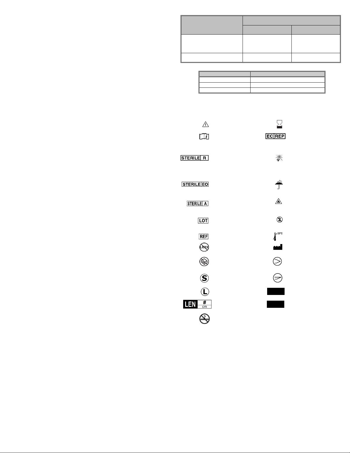
12
7) Bereid de StabiliT Inbrengspuit voor
a) Haal de plugkraan uit de verpakking van de StabiliT Inbrengspuit
b) Sluit het verlengstuk van de StabiliT-inbrengspuit aan op de vrouwelijke connector
op de plugkraan (tegenover de mannelijke connector).
c) Zorg ervoor dat de mannelijke poort op de plugkraan in de gesloten positie staat.
d) Breng de zuiger met voldoende kracht naar voren om alle lucht uit de spuit te
verwijderen.
e) Dompel de plugkraan onder in steriel water (of een zoutoplossing).
f) Knijp de trekker van StabiliT-inbrengspuit naar voren en trek de handgreep naar
achteren om de spuit met vloeistof te vullen. Doe dit totdat de hele spuit vol zit.
g) Keer de StabiliT-inbrengspuit om, knijp de trekker in en duw de zuiger naar voren
om alle resterende lucht uit de spuit en het verlengstuk te verwijderen.
h) Knijp de trekker van StabiliT Inbrengspuit in en trek hem naar achteren om de
spuit vol met steriel water (of zoutoplossing) te zuigen.
Let op: inspecteer de buis van de StabiliT Inbrengspuit en de plugkraan om ervoor
te zorgen dat er geen lucht in het systeem zit.
8) Monteer de componenten van het systeem
a) Verwijder één minuut voor het inbrengen van het botcement het filter en de
trechterassemblage (zie tabel 1). Verwijder overmatig botcement van de
cementspuit en draai de cementspuit volledig in de vergrendelende inbrengcanule
(LDC).
b) Draai de hoofdspuit op de cementspuit.
Let op: zorg ervoor dat de hoofdspuit IN ZIJN GEHEEL op de cementspuit is
gedraaid voordat u verder gaat. Als u dit nalaat kunnen letsel of
instrumentstoringen worden veroorzaakt.
c) Bevestig de StabiliT Inbrengspuit aan de hoofdspuit. Sluit de Luer van de
hoofdspuit aan op de plugkraan aan het uiteinde van het verlengstuk van de
StabiliT Inbrengspuit.
Let op: begin pas met het inbrengen van het botcement wanneer de saturatie-
en voorbereidingstijd is verstreken (zie tabel 1).
9) Inbrengen van cement
a) Controleer of de trekker van de StabiliT Inbrengspuit is vrijgegeven, om ervoor te
zorgen dat de zuiger is vergrendeld.
b) U kunt nu de LCD van te voren vullen met botcement door de handgreep van de
StabiliT Inbrengspuit TEGEN DE KLOK IN te draaien. Wanneer het botcement uit
de punt van de LCD komt, kunt u de cementstroom stoppen door de trekker op de
StabiliT Inbrengspuit in te knijpen. Laat de trekker weer los om de zuiger in de
teruggetrokken positie te vergrendelen. Veeg de punt van de LCD schoon.
c) Stabiliseer de werkcanule met fluoroscopische geleiding en breng de LDC in totdat
het draaiende wiel de Luer van de werkcanule raakt. Draai het wiel van de LDC
om de LDC aan de werkcanule vast te zetten.
d) Wanneer u klaar bent om het botcement in te brengen, kunt u de trekker van de
StabiliT Inbrengspuit inknijpen en de handgreep naar voren duwen totdat u
weerstand voelt. Daarna kunt u de trekker loslaten. Breng het botcement met
fluoriscopische geleiding in door de handgreep MET DE KLOK MEE te draaien.
e) Om het inbrengen van het botcement te stoppen, kunt u de trekker op de StabiliT
Inbrengspuit inknijpen. Laat de trekker weer los om de zuiger in de teruggetrokken
positie te vergrendelen. Om weer verder te gaan, kunt u de trekker inknijpen en
de handgreep naar voren duwen totdat u weerstand voelt. Daarna kunt u de
trekker loslaten. U kunt doorgaan met het inbrengen van botcement door de
handgreep MET DE KLOK MEE te draaien.
Let op: om de bedrading van de handgreep voor het ontgrendelen te
beschermen, moet de meter 25 ATM of minder aangeven voor dat het
mechanisme voor snelle vrijgave wordt gebruikt om de toevoer te stoppen en de
druk te verminderen.
Let op: de koppeling wordt ontkoppeld (dit wordt aangegeven door een
klikgeluid) indien de bediener de maximale druk voor de StabiliT Inbrengspuit
overschrijdt. Wanneer dit is gebeurd, kan de koppeling weer worden ontkoppeld
bij een lagere druk tijdens vervolgpogingen om de druk te verhogen.
Let op: Nadat het inbrengen van cement is voltooid, moet u de LDC binnen 1
minuut van de werkcanule verwijderen en onmiddellijk het inbrengstilet in de
werkcanule plaatsen en vergrendelen. Als inbrengen van aanvullend cement
niet is vereist, kunt u de Introducer (Canule met Stylet) verwijderen.
Waarschuwing: De Werkcanule mag uitsluitend worden verwijderd na het
insteken van het stilet met een trekkende, draaiende beweging. Buig de
Werkcanule niet opzij, hierdoor kan de de patiënt oplopen.
Tabel 1: Tijden van Verschillende Activiteiten bij Verschillende Omgevingstemperaturen
Activiteit
Geschatte cumulatieve tijd vanaf initiatie
van saturatie (in minuten)
bij 18-19 ℃
(65-55,00 ℃)
bij 20-23 ℃
(68-55,00 ℃)
Verzadiging en voorbereiding
van botcement
(Zie gebruiksinstructies
botcement)
0-10 minuten
0-5 minuten
Inbrengen van botcement
10-45 minuten
(35 minuten werktijd)
5-40 minuten
(35 minuten werktijd)
Tabel 2: Effect van Omgevingstemperatuur op Cement
Temperatuur ºF (ºC)
Minimale instellingstijd (in minuten)
81 (27)
35
73 (23)
51
66 (19)
82
OPSLAG EN HANTERING
Voorzichtig behandelen. Bewaren in de originele verpakking op een schone, koele, droge
locatie. Vermijd blootstelling aan extreme temperaturen en vochtigheid.
SYMBOLENVERKLARING
Let op
Te gebruiken voor
Instructies voor het
gebruik raadplegen
Gemachtigde
Vertegenwoordiger in de
Europese Gemeenschap
Gesteriliseerd met
straling
(Levering van
Instrumenten,
Osteotomen en
Introducer)
Verwijderd van zonlicht
houden
Gesteriliseerd met
behulp van
ethyleenoxide
(botcementpoeder en
inbrengspuit)
Uit de buurt van vocht
houden
Gesteriliseerd met
behulp van filtratie
(botcementvloeistof)
Brandbaar
Partijnummer
Instrument voor eenmalig
gebruik, NIET OPNIEUW
GEBRUIKEN
Catalogusnummer
Bewaren onder 25 °C
Geen Latex
Fabrikant
Gebruik het product niet
als de verpakking
beschadigd of geopend
is
Diamanten punt
Kort
Schuine punt
Lang
Canulemaat
Lengte van instrument
in centimeters
Maat inbrenger/maat
vergrendelende
inbrengcanule
Niet opnieuw steriliseren
QTY:
Hoeveelheid
# G
# / # G

13
Système d'augmentation vertébrale StabiliT®MX
(à utiliser avec le ciment osseux StabiliT®)
Mode d’emploi (Français) (FR)
Informations importantes - Lire avant utilisation
ATTENTION : selon la législation fédérale (États-Unis) ce dispositif ne peut être
vendu que par un médecin ou sur ordonnance médicale.
INDICATIONS
Le système d'augmentation vertébrale StabiliT®MX est prévu pour l'administration percutanée
de ciment osseux StabiliT®. Le ciment osseux StabiliT® est indiqué pour le traitement des
fractures pathologiques des vertèbres ayant recours à une procédure de vertébroplastie ou de
kyphoplastie. Les fractures vertébrales douloureuses par compression peuvent entraîner une
ostéoporose, des lésions bénignes (hémangiome) et des lésions malignes (cancers
métastatiques, myélome).
L'ostéotome VertecoR® MidLine pour application de ciment, l'ostéotome VertecoR®Midline
(MLO), l'ostéotome VertecoR® StraightLine 3.0-11.5 pour application de ciment et l'ostéotome
VertecoR® StraightLine 3.0 (SLO) pour application de ciment sont conçus pour le curetage ou la
perforation de l'os de la colonne vertébrale.
DESCRIPTION
Le système d'augmentation vertébrale StabiliT MX est un système conçu pour l'administration
contrôlée de ciment osseux StabiliT pour le traitement des fractures vertébrales par
compression. Le système d'augmentation vertébrale StabiliT MX peut comprendre un
maximum de huit (8) composants (Figure 1).
Figure 1. Système d'augmentation vertébrale StabiliT MX
Seringue d'administration StabiliT (n° 1) : utilisée pour l'administration du ciment osseux
dans le corps vertébral.
Instruments d'administration StabiliT (n° 2, 3, 4) : utilisés pour accéder au corps vertébral
et faciliter l'administration du ciment osseux en PMMA au cours des interventions
orthopédiques, notamment les interventions de vertébroplastie ou de kyphoplastie.
oSeringue principale (n° 2)
oCanule d'administration à verrou (CAV) (n° 3)
Canule (3a)
Stylet (3b)
oIntroducteur StabiliT avec stylet à pointe diamantée (n° 4) : l'introducteur StabiliT est
utilisé pour un accès percutané à l'os. Le dispositif est fourni avec un stylet à pointe
diamantée et une canule. Le diamètre extérieur de la canule de l'introducteur est de
3,6 mm. Consulter le tableau ci-dessous pour connaître la longueur du dispositif.
Canule (4a)
Stylet (4b)
L'introducteur StabiliT est fourni avec un stylet à pointe biseautée (n° 5) dans certains types
de kits (voir étiquette produit pour plus d'informations) : l'introducteur StabiliT avec pointe
biseautée est utilisé pour un accès percutané à l'os. Le dispositif est fourni avec un stylet à
pointe biseautée et une canule. Le diamètre extérieur de la canule de l'introducteur est de
3,6 mm. Consulter le tableau ci-dessous pour connaître la longueur du dispositif.
Canule (5a)
Stylet (5b)
Dispositif
Longueur utile
Introducteur StabiliT 3.6-11.5
11 cm
Introducteur StabiliT 3.6
13 cm
Système de mélange saturé et ciment osseux StabiliT (n° 6) :
oLe ciment osseux StabiliT est indiqué pour le traitement des fractures pathologiques
des vertèbres ayant recours à une intervention de vertébroplastie ou de kyphoplastie.
Les fractures vertébrales douloureuses par compression peuvent entraîner une
ostéoporose, des lésions bénignes (hémangiome) et des lésions malignes (cancers
métastatiques, myélome).
oLe système de mélange saturé est prévu pour le mélange du ciment osseux StabiliT.
Entonnoir (n° 6a)
Seringue à ciment (n° 6b)
Filtre (n° 6c)
Seringue à verrou (n° 6d)
Monomère (n° 6e)
L'ostéotome VertecoR MidLine pour application de ciment (MLO) (n° 7) est un dispositif
stérile à usage unique pour le curetage ou la perforation de l'os afin de créer une zone où le
ciment pourra être appliqué dans le cadre du traitement des fractures vertébrales par
compression. Il doit être utilisé avec l'introducteur StabiliT. Le diamètre extérieur de la tige
est de 3 mm. Consulter le tableau ci-dessous pour connaître la longueur utile.
Dispositif
Longueur utile
Ostéotome MidLine 3.0-11.5 pour application
de ciment
14,5 cm
Ostéotome MidLine 3.0 pour application de
ciment
16,5 cm
A. MLO
B1. Le manche de déploiement est la partie étroite et
rotative du manche du MLO. La flèche directionnelle B2
pointe dans la direction de l'extrémité articulée.
C. Extrémité articulée non
déployée
D. Extrémité
articulée déployée
Le MLO (A) est muni d'un manche (B) qui contient un manche de
déploiement rotatif qui déploie l'extrémité articulée (C, D).
Ostéotome VertecoR StraightLine pour application de ciment (SLO) (n° 8) dans certains
types de kits (voir étiquette produit pour plus d'informations) : le SLO est un dispositif stérile
à usage unique pour le curetage ou la perforation de l'os visant à créer une zone où le
ciment pourra être appliqué dans le cadre du traitement des fractures vertébrales par
compression. Il permet en outre de réaliser une biopsie. Il est fourni avec un stylet à pointe
arrondie. Il doit être utilisé avec l'introducteur StabiliT. Le diamètre extérieur de la tige est
de 3 mm. Consulter le tableau ci-dessous pour connaître la longueur utile.
Canule (8a)
Stylet (8b)
Dispositif
Longueur utile
Ostéotome VertecoR StraightLine 3.0-11.5
pour application de ciment
13,5 cm
Ostéotome VertecoR StraightLine 3.0 pour
application de ciment
15,5 cm
PRÉSENTATION
Tous les composants sont fournis stériles. Ces dispositifs sont réservés à un usage unique.
NE PAS restériliser et/ou réutiliser le dispositif. NE PAS utiliser si l'emballage a été ouvert ou
endommagé et le signaler au fabricant.
CONTRE-INDICATIONS
L'utilisation de ce produit est contre-indiquée chez les patients présentant des troubles de la
coagulation ou une insuffisance respiratoire grave.
L'utilisation de ce produit est contre-indiquée chez les patients présentant une atteinte au
niveau de la colonne postérieure du corps vertébral ou sur les parois des pédicules.
L'utilisation du ciment osseux PMMA est contre-indiquée en la présence d'infection active ou
traitée de manière incomplète, sur la zone où le ciment osseux doit être appliqué.
Ce produit ne doit pas être utilisé sur des patients présentant une sensibilité à l'un des
composants du ciment osseux PMMA.
AVERTISSEMENTS
Avant utilisation, lire attentivement les modes d'emploi fournis pour chaque dispositif,
notamment concernant le système de mélange saturé et ciment osseux StabiliT (s'ils sont
emballés séparément ou avec le présent mode d'emploi). Le mode d'emploi doit être suivi
lors d'une intervention exécutée au moyen du système d'augmentation vertébrale StabiliT
MX.
Pour une utilisation sûre et efficace, ce dispositif doit être utilisé uniquement par des
médecins qualifiés ayant reçu une formation relative à l'intervention clinique dans laquelle le
dispositif est employé. Le médecin doit avoir reçu une formation spécifique, avoir de
l'expérience et être complètement familiarisé avec l'utilisation et l'application de ce produit.

14
L'intervention doit toujours être effectuée sous observation fluoroscopique avec un
équipement radiographique qui fournit des images de haute qualité pour éviter de
provoquer des lésions au patient. Utiliser des techniques d'imagerie appropriées pour
confirmer le bon placement de la canule de travail (avant et pendant son placement et
après son retrait), l'absence de dommages aux structures environnantes et le bon
emplacement du ciment osseux administré. Des techniques d'imagerie, telles que la
phlébographie, peuvent être utilisées pour évaluer la capacité de la vertèbre à contenir le
ciment osseux administré.
Il est essentiel de conserver une technique stérile stricte pendant l'intervention et durant
l'ensemble des phases de manipulation de ce produit.
La canule de travail doit être positionnée avec précision au cours de cette intervention. Un
mauvais positionnement du dispositif peut entraîner des risques de blessure pour le patient.
La canule de travail (élément de l'introducteur StabiliT) n'est pas prévue pour
l'administration du ciment osseux. Toujours utiliser la CAV pour administrer du ciment
osseux dans le corps vertébral.
Le stylet de l'introducteur doit être placé à l'intérieur de la canule de travail pendant son
utilisation (ex : insertion, retrait, manipulation).
Le retrait de la canule de travail doit être réalisé en effectuant une rotation et un
mouvement axial. NE PAS plier la canule sur les côtés, sous peine de provoquer des lésions
au patient.
Mettre au rebut le produit usagé conformément aux normes locales, régionales et fédérales
en matière de pathogènes transmissibles par le sang, notamment les conteneurs
d'éléments pointus dangereux, et dans le respect des procédures de mise au rebut.
Ne PAS utiliser si l'emballage est ouvert ou endommagé. Tous les dispositifs sont
fournis stériles. Tous les dispositifs sont stérilisés par rayons gamma. Ces dispositifs sont
réservés à un usage unique. NE PAS restériliser ou réutiliser. Le reconditionnement, la
remise à neuf, la réparation, la modification ou la restérilisation des dispositifs pour
permettre un usage supplémentaire sont formellement interdits, sous peine de lésions pour
le patient, comme une perte de capacités fonctionnelles ou une infection.
Pour les dispositifs pénétrant l'os, NE PAS réutiliser sur les os denses, notamment sur les
fractures traumatiques. Cela risquerait d'endommager le dispositif et de blesser le patient.
La rupture du dispositif peut nécessiter l'intervention ou l'extraction.
Ne PAS utiliser l'ostéotome StraightLine ou l'ostéotome MidLine sur les fractures de la
colonne vertébrale causées par des métastases cancérigènes pararénales ou prostatiques.
Ne PAS utiliser un ostéotome MidLine pour cureter ou perforer l'os dans plus d'une vertèbre.
PRÉCAUTIONS
Examiner tous les emballages avant de les ouvrir. NE PAS utiliser le dispositif s'il est
endommagé ou si l'emballage stérile est percé. Contacter le fabricant si l'emballage est
ouvert ou endommagé.
Utiliser le dispositif avant la date d'expiration notée sur l'emballage du dispositif.
Porter des lunettes de sécurité ou un masque de protection lors de l'administration du
ciment osseux.
S'assurer que tous les connecteurs luer-lock sont fermement installés. Des raccordements
mal effectués peuvent provoquer la déconnexion du dispositif pendant l'injection.
NE PAS insérer l'ostéotome StraightLine dans la canule de travail si le stylet est toujours fixé
à l'ostéotome StraightLine, sous peine de perforation inappropriée de l'os.
Procéder avec précaution pour les cas impliquant une destruction vertébrale importante et
un tassement vertébral significatif (par ex., le corps vertébral mesure moins d'1/3 de sa
hauteur d'origine). De tels cas peuvent donner lieu à une intervention techniquement
difficile.
EFFETS INDÉSIRABLES
Les effets indésirables graves, certains à l'issu fatale, associés à l'utilisation du
polyméthylméthacrylate (PMMA) incluent :
Infarctus du myocarde
Arrêt cardiaque
Accident vasculaire cérébral
Embolie pulmonaire
Anaphylaxie
Diffusion du ciment osseux à l'extérieur du corps vertébral : dans les veines
périphériques (embolie pulmonaire), dans le plexus épidural (myélopathie,
radiculopathie), dans le disque intervertébral
Effets indésirables les plus fréquents signalés avec le PMMA :
Chute transitoire de la pression artérielle
Thrombophlébite
Hémorragie et hématome
Infection de plaie superficielle ou profonde
Bursite
Troubles cardiaques à court terme
Formation osseuse hétérotopique
Autres effets indésirables potentiels signalés avec le PMMA :
Pyrexie
Hématurie
Dysurie
Fistule vésicale
Aggravation transitoire de la douleur provoquée par la chaleur libérée lors de la
polymérisation
Syndrome canalaire et dysphasie causés par l'extrusion du ciment osseux au-delà de son
application prévue
Adhérences et rétrécissement de l'iléon provoqués par la chaleur libérée lors de la
polymérisation
Effets indésirables potentiels associés à la kyphoplastie ou la vertébroplastie :
Pneumonie
Névralgie intercostale
Tassement d'une vertèbre adjacente à celle injectée, en raison d'une maladie
ostéoporotique
Pneumothorax
Extravasation du ciment osseux dans une partie molle
Fracture d'un pédicule
Fracture costale chez les patients souffrant d'ostéopénie diffuse, en particulier lors des
interventions de kyphoplastie thoracique, en raison d'une pression importante exercée
vers le bas pendant l'insertion de la canule de travail.
Compression de la moelle épinière avec paralysie ou perte de sensation.
Les effets indésirables potentiels associés à l'utilisation de l'introducteur StabiliT, de
l'ostéotome MidLine ou des ostéotomes StraightLine incluent :
Lésion nerveuse, y compris perforation de la moelle ou des racines nerveuses résultant
potentiellement en une radiculopathie, parésie ou paralysie
Embolie pulmonaire
Hémothorax ou pneumothorax
Infection, y compris infection de plaie profonde ou superficielle
Plaies punctiformes non intentionnelles, y compris ponction vasculaire et déchirure durale
Hémorragie
Hématome
Douleur
PRÉPARATION ET UTILISATION
1) Vérifier que l'emballage ne présente pas de dommages avant de positionner son contenu
sur le champ stérile.
2) Retirer le produit de l'emballage à l'aide de la technique stérile standard.
3) Vérifier que l'ensemble des composants ne présente pas de dommages. Ne pas utiliser
si l'aiguille du manomètre de la seringue d'administration StabiliT se trouve en dehors de
la case « 0 ».
4) Mélanger le ciment osseux conformément au mode d'emploi du système de mélange
saturé et ciment osseux StabiliT.
5) Accès au corps vertébral à l'aide de l'introducteur StabiliT.
a) Sous observation fluoroscopique, guider l'introducteur StabiliT vers le pédicule du
corps vertébral, en vérifiant les images antéro-postérieures/latérales pour
confirmer le positionnement correct du dispositif.
b) Une fois l'introducteur StabiliT positionné dans le corps vertébral, retirer le stylet en
tournant dans le sens inverse des aiguilles d'une montre et en laissant la canule de
travail en position.
6) Créer un canal d'accès et une zone pour l'application de ciment afin d'administrer le
ciment osseux au moyen du SLO ou du MLO.
AVERTISSEMENT : utiliser l'observation fluoroscopique et suivre le mode d'emploi pour
éviter de provoquer des lésions au patient.
a) Utiliser le SLO pour créer un canal d'accès et une zone pour l'application de ciment
dans l'os :
i) Retirer le stylet du SLO et le mettre de côté avant d'insérer le LSO dans la
canule de travail.
ii) Retirer tous les instruments de la canule de travail.
iii) À l'aide de l'observation fluoroscopique, avancer le SLO à travers la canule
de travail, le mettre en contact avec l'os et vérifier l'emplacement de
l'extrémité du SLO à l'endroit visé. La butée de l'introducteur / du SLO
empêche l'axe du SLO de s'étendre de plus de 15 mm au-delà de l'extrémité
distale de la canule de travail. Toujours vérifier l'emplacement sous
observation fluoroscopique.
iv) À l'aide de l'observation fluoroscopique, avancer l'extrémité du SLO jusqu'à
l'emplacement désiré pour racler ou perforer l'os avec précaution.
Attention : l'emplacement de la canule de travail dans la vertèbre doit être
contrôlé avant et pendant l'avancement du SLO.
v) Installer complètement le SLO sur la canule de travail pour créer l'espace
destiné à l'application du ciment. Il peut être nécessaire d'extraire la canule
de travail.
vi) À la fin du curetage ou de la perforation, à l'aide de l'observation
fluoroscopique, retirer le SLO de la canule de travail.
b) Utiliser le MLO pour créer un canal d'accès et une zone pour l'application de ciment
dans l'os :
i) L'extrémité articulée est la partie distale du MLO ; la flèche directionnelle
pointe dans la direction de la flexion de l'extrémité articulée.
ii) Le manche de déploiement est la partie rotative du manche du MLO.
(1) En tournant le manche de déploiement d'un demi-tour dans le sens
des aiguilles d'une montre, l'extrémité se déploiera (flexion complète).
(2) En tournant le manche de déploiement d'un tour dans le sens inverse
des aiguilles d'une montre, l'extrémité articulée ne se déploiera pas
(droite).
(3) Ne pas déployer le manche de déploiement de plus d'un demi-tour
dans le sens inverse des aiguilles d'une montre.
iii) S'assurer que l'extrémité articulée est entièrement étendue en position
droite avant l'insertion dans la canule de travail.
iv) Retirer le stylet de la canule de travail.
v) Insérer le MLO dans la canule de travail jusqu'à ce que la première marque
du laser de l'axe se trouve au niveau de l'extrémité proximale du luer de la
canule de travail. Confirmer sous fluoroscopie que l'extrémité distale du MLO
se trouve au niveau de l'extrémité distale de la canule de travail avant de
continuer. Lorsqu'elle est entièrement insérée dans la canule de travail, l'axe
s'étend d'environ 26 mm au-delà de l'extrémité distale de la canule de
travail.
vi) Lorsque l'extrémité articulée sort de la canule de travail, tourner le manche
de déploiement pour plier l'extrémité articulée dans la direction de la flèche
sur le manche du MLO.
vii) Le MLO peut être avancé jusqu'à la position désirée sous observation
fluoroscopique.
viii) Des précautions doivent être prises à tout moment afin de ne JAMAIS
heurter les bras du manche de déploiement, en particulier lorsqu'il a pivoté
et quitté sa position de départ.
ix) Sous observation fluoroscopique (et en stabilisant la canule de travail), le
MLO peut être retiré avec précaution et avancé à plusieurs reprises pour
cureter ou perforer l'os jusqu'à la création de la cavité désirée (taille et
emplacement).
x) Lorsque l'extrémité articulée est en grande partie déployée, le MLO ne doit
pas être pivoté.
(1) Si le grand manche est pivoté alors que l'extrémité articulée est en
grande partie articulée, le mécanisme de limitation de la rotation
interviendra.
Attention : l'emplacement de la canule de travail dans la vertèbre
doit être contrôlé avant et pendant l'avancement du MLO à travers la
canule de travail.
xi) Lorsque la création de la cavité est terminée, sous observation
fluoroscopique, rétracter l'extrémité articulée et remettre le manche de
déploiement en position de départ.
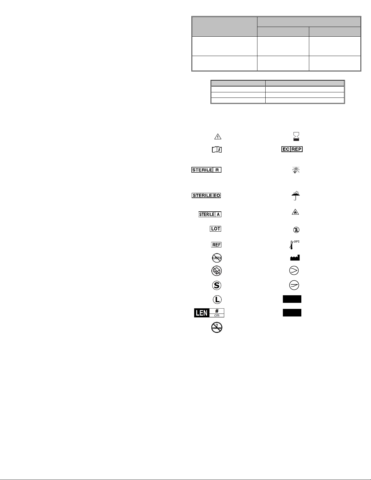
15
Attention : la rétractation de l'extrémité articulée doit être effectuée
lentement et sous observation fluoroscopique, tout en contrôlant
soigneusement la position de l'extrémité du dispositif. Rétracter le dispositif
en tournant le manche de déploiement dans le sens inverse des aiguilles
d'une montre.
xii) Sous fluoroscopie, retirer le MLO de la canule de travail de l'introducteur
StabiliT.
xiii) L'emplacement de la canule de travail de l'introducteur StabiliT dans la
vertèbre doit être contrôlé et ajusté si nécessaire après l'extraction du MLO.
7) Préparer la seringue d'administration StabiliT.
a) Retirer le robinet d'arrêt de l'emballage de la seringue d'administration StabiliT.
b) Connecter le tube d'extension de la seringue d'administration StabiliT au
connecteur femelle, sur le robinet d'arrêt (à l'opposé du connecteur mâle).
c) S'assurer que le port mâle du robinet d'arrêt est fermé.
d) Faire avancer le piston avec suffisamment de force pour éliminer complètement
l'air présent dans la seringue.
e) Immerger le robinet d'arrêt dans de l'eau stérile (ou saline).
f) Appuyer sur le déclencheur de la seringue d'administration StabiliT et tirer sur la
poignée pour remplir la seringue de fluide. Procéder ainsi jusqu'à remplir
entièrement la seringue.
g) Inverser la seringue d'administration StabiliT, appuyer sur le déclencheur et faire
avancer le piston pour éliminer l'air restant dans la seringue et le tube d'extension.
h) Appuyer sur le déclencheur de la seringue d'administration StabiliT et tirer
complètement pour aspirer l'eau stérile (ou saline).
Attention : inspecter la tubulure de la seringue d'administration StabiliT et le
robinet d'arrêt pour vérifier qu'il n'y a pas d'air dans le système.
8) Assembler les éléments du système
a) Une minute avant l'administration du ciment osseux (voir le tableau 1), retirer le
filtre et l'entonnoir. Nettoyer les restes de ciment osseux dans la seringue à ciment
et l'enfiler complètement dans la canule d'administration à verrou.
b) Enfiler la seringue principale dans la seringue à ciment.
Attention :s'assurer que la seringue principale est COMPLÈTEMENT enfilée dans la
seringue à ciment avant de continuer. Le non-respect de cette consigne peut
entraîner des risques de blessure ou un dysfonctionnement du dispositif.
c) Raccorder la seringue d'administration StabiliT à la seringue principale. Raccorder
fermement le luer de la seringue principale au robinet d'arrêt à l'extrémité du tube
d'extension de la seringue d'administration StabiliT.
Attention : ne pas commencer l'administration du ciment osseux avant la fin de
la période de saturation et de préparation (voir le tableau 1).
9) Administration du ciment
a) Confirmer que le déclencheur de la seringue d'administration StabiliT est relâché
afin de s'assurer que le piston est bien verrouillé.
b) Préparer la CAV avec le ciment osseux en faisant tourner la poignée de la seringue
d'administration StabiliT dans le SENS DES AIGUILLES D'UNE MONTRE. Lorsque
le ciment osseux ressort de l'embout de la CAV, arrêter l'écoulement du ciment en
appuyant sur le déclencheur de la seringue d'administration StabiliT. Relâcher le
déclencheur pour verrouiller le piston en position rétractée. Nettoyer l'embout de
la CAV.
c) Sous observation fluoroscopique, stabiliser la canule de travail et insérer la CAV
jusqu'à ce que la roue giratoire entre en contact avec le luer de la canule de travail.
Tourner la roue de la CAV pour bloquer la CAV dans la canule de travail.
d) Pour administrer le ciment osseux, appuyer sur le déclencheur de la seringue
d'administration StabiliT et pousser la poignée vers l'avant jusqu'à ce qu'une
résistance se fasse sentir, puis relâcher le déclencheur. Sous observation
fluoroscopique, administrer le ciment osseux en tournant la poignée dans le SENS
DES AIGUILLES D'UNE MONTRE.
e) Pour arrêter l'administration du ciment osseux, appuyer sur le déclencheur de la
seringue d'administration StabiliT. Relâcher le déclencheur pour verrouiller le piston
en position rétractée. Pour reprendre, appuyer sur le déclencheur et pousser la
poignée vers l'avant jusqu'à ce qu'une résistance se fasse sentir, puis relâcher le
déclencheur. Continuer l'administration du ciment osseux en tournant la poignée
dans le SENS DES AIGUILLES D'UNE MONTRE.
Attention : pour protéger le filetage de la poignée de déverrouillage, la jauge doit
indiquer 25 ATM ou moins avant de pouvoir utiliser le mécanisme de blocage
rapide pour arrêter l'écoulement et relâcher la pression.
Attention : le mécanisme de blocage rapide s'enclenche (indiqué par un clic
audible) si l'utilisateur dépasse la pression maximale pour la seringue
d'administration StabiliT. Lorsque cela se produit, le mécanisme de blocage rapide
peut se désenclencher à des pressions plus basses lors des tentatives
subséquentes d'augmentation de la pression.
Attention : une fois l'administration de ciment osseux terminée, retirer la CAV de
la canule de travail en moins d'une minute et insérer et bloquer immédiatement le
stylet dans la canule de travail. Si aucune intervention d'administration de ciment
osseux supplémentaire n'est nécessaire, retirer l'introducteur (canule avec stylet).
Avertissement : la canule de travail ne peut être retirée qu'après l'insertion du
stylet, qui s'effectue grâce à une rotation et un mouvement axial. NE PAS plier la
canule de travail sur les côtés, sous peine de provoquer des lésions au patient.
Tableau 1 : temps des diverses activités en fonction des différentes températures ambiantes
Activité
Temps cumulé approximatif depuis le début
de la saturation (minutes)
à 18-19 °C
(65-67 °F)
à 20-23 °C
(68-74 °F)
Saturation et préparation du
ciment osseux
(Consulter le mode d'emploi
du ciment osseux)
0-10 minutes
0-5 minutes
Administration du ciment
osseux
10-45 minutes
(temps de travail :
35 minutes)
5-40 minutes
(temps de travail :
35 minutes)
Tableau 2 : effets de la température ambiante sur le ciment
Température ºC (ºF)
Temps minimum de prise (minutes)
81 (27)
35
73 (23)
51
66 (19)
82
STOCKAGE ET MANIPULATION
Manipuler avec précaution. Stocker dans l'emballage d'origine dans un endroit propre, frais et
sec. Éviter l'humidité et les températures extrêmes.
GLOSSAIRE DES SYMBOLES
Attention
Date d'expiration
Consulter le mode
d'emploi
Représentant autorisé de
la Communauté
européenne
Stérilisé par radiation
(Instruments
d'administration,
ostéotomes et
introducteur)
Protéger de la lumière du
soleil
Stérilisé à l'oxyde
d'éthylène (seringue
d'administration et
poudre de ciment
osseux)
Protéger de l'humidité
Stérilisé par filtration
(ciment osseux liquide)
Inflammable
Numéro de lot
Dispositif à usage unique,
NE PAS RÉUTILISER
Numéro de catalogue
Stocker à une
température inférieure à
25 °C
Sans latex
Fabricant
Ne pas utiliser si
l'emballage est ouvert
ou endommagé
Pointe diamantée
Courte
Pointe biseautée
Longue
Calibre de la canule
Longueur du dispositif
en centimètres
Calibre de l’introducteur /
calibre de la canule
d’administration à verrou
Ne pas restériliser.
QTY:
Quantité
# / # G
# G
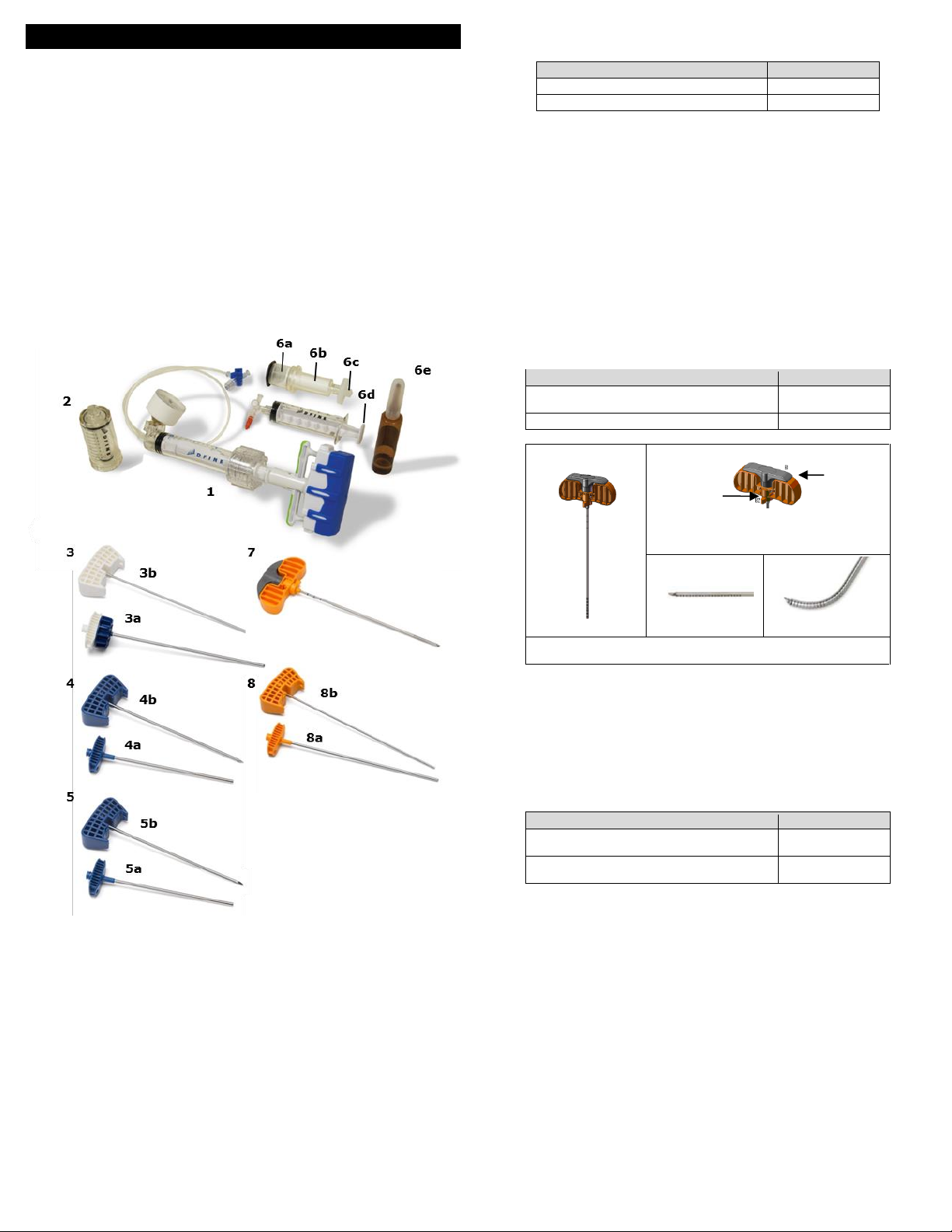
16
StabiliT®MX Wirbelsäulenaugmentationssystem
(zur Nutzung mit StabiliT®Knochenzement)
Gebrauchsanleitung (Deutsch) (DE)
Wichtige Informationen – bitte vor Gebrauch lesen
VORSICHT: Laut US-Bundesgesetz darf dieses Produkt nur von einem Arzt oder auf ärztliche
Anordnung hin verkauft werden.
INDIKATIONEN
Das StabiliT®MX-Wirbelsäulenaugmentationssystem ist für die perkutane Abgabe von StabiliT®
-Knochenzement. Der StabiliT®-Knochenzement eignet sich für die Behandlung von
pathologischen Frakturen der Wirbelkörper unter Einsatz eines Vertebroplastie- oder
Kyphoplastieverfahrens. Schmerzhafte Kompressionsfrakturen der Wirbelkörper können durch
Osteoporose, gutartige Läsionen (Hämangiome) und bösartige Läsionen (Metastasen,
Myelome) verursacht werden.
Das VertecoR®Mittellinien-Zement-Staging Osteotom, das VertecoR®Mittelinien-Osteotom
(MLO), das VertecoR®Geradlinien-Zement-Osteotom 3.0-11.5 und das VertecoR®Geradlinien-
Zement-Staging-Osteotom 3.0 (SLO) sind zum Schaben oder Kernbohren von Knochen in der
Wirbelsäule vorgesehen.
BESCHREIBUNG
Das StabiliT MX-Wirbelsäulenaugmentationssystem ist ein System zur kontrollierten Abgabe
von StabiliT-Knochenzement bei der Behandlung von Kompressionsfrakturen der Wirbelsäule.
Das StabiliT MX-Wirbelsäulenaugmentationssystem besteht aus bis zu acht (8) Komponenten
(Abbildung 1).
Abbildung 1. StabiliT MX-Wirbelsäulenaugmentationssystem
StabiliT Applikationsspritze (#1) - Zur Abgabe von Knochenzement in den Wirbelkörper.
StabiliT-Applikationsinstrumente (#2, 3, 4) - Zur Herstellung des Zugangs zum
Wirbelkörper und Erleichterung der Applikation von PMMA-Knochenzement bei
orthopädischen Verfahren einschließlich Vertebroplastie oder Kyphoplastie.
oHauptspritze (#2)
oSperrabgabekanüle (LDC) (#3)
Kanüle (3a)
Mandrin (3b)
oStabiliT-Einführbesteck mit Diamantspitzenmandrin (#4) - Das StabiliT-
Einführbesteck wird für den perkutanen Knochenzugang eingesetzt. Das Gerät wird
mit einem Diamantspitzenmandrin und einer Kanüle verpackt. Die Kanüle des
Einführbestecks hat einen Außendurchmesser von 3,6 mm. Die Gerätelänge
entnehmen Sie bitte der folgenden Tabelle.
Kanüle (4a)
Mandrin (4b)
StabiliT-Einführbesteck mit Mandrin mit abgeschrägter Spitze (#5) in einigen Kit-
Konfigurationen (wegen Einzelheiten siehe Produktetikett) – Das StabiliT-Einführbesteck mit
abgeschrägter Spitze wird für den perkutanen Knochenzugang verwendet. Das Gerät wird
mit einem Mandrin mit abgeschrägter Spitze und einer Kanüle verpackt. Die Kanüle des
Einführbestecks hat einen Außendurchmesser von 3,6 mm. Die Gerätelänge entnehmen
Sie bitte der folgenden Tabelle.
Kanüle (5a)
Mandrin (5b)
Gerät
Arbeitslänge
StabiliT Einführbesteck 3,6-11,5
11 cm
StabiliT Einführbesteck 3,6
13 cm
StabiliT Knochenzement und Sättigungsmischsystem (#6) -
oDer StabiliT-Knochenzement eignet sich für die Behandlung von pathologischen
Frakturen der Wirbelkörper unter Einsatz eines Vertebroplastie- oder
Kyphoplastieverfahrens. Schmerzhafte Kompressionsfrakturen der Wirbelkörper
können durch Osteoporose, gutartige Läsionen (Hämangiome) und bösartige
Läsionen (Metastasen, Myelome) verursacht werden.
oDas Sättigungsmischsystem ist zum Mischen des StabiliT-Knochenzements
vorgesehen.
Trichter (#6a)
Zementspritze (#6b)
Filter (#6c)
Sperrspritze (#6d)
Monomer (#6e)
VertecoR Mittellinien-Zement-Staging-Osteotom (MLO) (#7) – Das MLO ist eine steriles
Einweg-Osteotom zum Schaben oder Kernbohren von Knochen zur Erzeugung eines Areals,
in das die Zementeinführung bei der Behandlung von Kompressionsfrakturen der
Wirbelsäule eingeleitet werden kann. Es ist mit dem StabiliT-Einführbesteck zu verwenden.
Der Schaft hat einen Außendurchmesser von 3,0 mm. Die Arbeitslängen entnehmen Sie
bitte der folgenden Tabelle.
Gerät
Arbeitslänge
Mittellinien-Zement-Staging Osteotom 3,0-
11,5
14,5 cm
Mittellinien-Zement-Staging Osteotom 3,0
16,5 cm
A. MLO
B1. Der Ausfahrgriff ist der dünne drehbare
Teil des MLO-Griffs. B2 Ein Richtungspfeil
zeigt auf die Gelenkspitze.
C. Gelenkspitze
unausgefahren
D. Gelenkspitze
ausgefahren
Das MLO (A) hat einen Griff (B) mit einem drehbaren Ausfahrgriff
zum Ausfahren der Gelenkspitze (C, D).
VertecoR Geradlinien-Zement-Staging-Osteotom (SLO) (#8) in einigen Kit-Konfigurationen
(wegen Einzelheiten siehe Produktetikett) – Das SLO ist ein steriles Einweg-Osteotom zum
Schaben oder Kernbohren von Knochen zur Erzeugung eines Areals, in das die
Zementeinführung bei der Behandlung von Kompressionsfrakturen der Wirbelsäule
eingeleitet werden kann, um eine Biopsie durchzuführen. Es ist mit einem Mandrin mit
stumpfer Spitze verpackt. Es ist mit dem StabiliT-Einführbesteck zu verwenden. Der Schaft
hat einen Außendurchmesser von 3,0 mm. Die Arbeitslängen entnehmen Sie bitte der
folgenden Tabelle.
Kanüle (8a)
Mandrin (8b)
Gerät
Arbeitslänge
VertecoR Geradlinien-Zement-Staging-
Osteotom 3,0-11,5
13,5 cm
VertecoR Geradlinien-Zement-Staging-
Osteotom 3,0
15,5 cm
LIEFERFORM
Alle Komponenten werden steril geliefert. Diese Komponenten sind für den Einmalgebrauch
bestimmt. NICHT resterilisieren und/oder wiederverwenden. Inhalt bei beschädigter oder
geöffneter Verpackung NICHT verwenden und den Hersteller verständigen.
KONTRAINDIKATIONEN
Die Verwendung dieses Produkts ist bei Patienten, die an Gerinnungsstörungen oder
erheblicher Lungeninsuffizienz leiden, kontraindiziert.
Der Gebrauch dieses Produkts ist bei Patienten mit beeinträchtigter posteriorer Säule des
Wirbelkörpers oder der Pedikelwände kontraindiziert.
Die Verwendung von PMMA-Knochenzement ist bei bestehenden aktiven oder unzureichend
behandelten Infektionen an der Stelle, an der der Knochenzement angewendet werden soll,
kontraindiziert.
Dieses Produkt sollte nicht bei Patienten verwendet werden, die an einer
Überempfindlichkeit gegen einen der Inhaltsstoffe von PMMA-Knochenzement leiden.
WARNHINWEISE
Lesen Sie die Anweisungen für jedes Gerät, einschließlich des StabiliT Knochenzements und
Sättigungsmischsystems, in den folgenden Gebrauchsanleitungen (IFU) durch. Beachten
Sie die Gebrauchsanleitung zur Durchführung eines Verfahrens mit dem StabiliT MX-
Wirbelsäulenaugementationssystem.
Zur sicheren und wirksamen Verwendung darf dieses Produkt nur von Fachärzten eingesetzt
werden, die in den entsprechenden klinischen Verfahren geschult wurden. Der Arzt sollte
entsprechend geschult sein und über Erfahrung und umfassende Kenntnisse in der
Verwendung und Handhabung dieses Produkts verfügen.

17
Verwenden Sie stets eine Röntgendurchleuchtung mit Röntgengeräten, die hochqualitative
Bilder liefern, um Verletzungen des Patienten zu vermeiden. Es sind geeignete
Bildgebungstechniken zu verwenden, um die korrekte Platzierung der Arbeitskanüle zu
bestätigen (vor und während des Vorschiebens und nach dem Entfernen) sowie zur
Kontrolle, dass die umliegenden Strukturen nicht beschädigt wurden und der abgegebene
Knochenzement an der vorgesehenen Stelle platziert wurde. Bildgebung wie Venographie
kann verwendet werden, um die Fähigkeit des Wirbels, den abgegebenen Knochenzement
aufzunehmen, zu beurteilen.
Während des Verfahrens und der Handhabung des Produkts muss jederzeit eine strikte
sterile Vorgehensweise eingehalten werden.
Dieses Verfahren erfordert eine präzise Platzierung der Arbeitskanüle. Eine unsachgemäße
Platzierung der Vorrichtung könnte zu einer Verletzung des Patienten führen.
Die Arbeitskanüle (Teil des StabiliT-Einführbestecks) ist nicht für die Knochenzementabgabe
bestimmt. Zur Abgabe von Knochenzement in den Wirbelkörper immer die LDC
verwenden.
Der Mandrin des Einführbestecks muss während der Verwendung in der Arbeitskanüle
platziert werden (z. B., Einsetzen, Entfernen, Handhabung).
Das Entfernen der Arbeitskanüle muss durch Drehung und axiale Bewegung erfolgen. Die
Arbeitskanüle NICHT zur Seite hin verbiegen, da dies zu einer Verletzung des Patienten
führen könnte.
Gebrauchte Produkte gemäß den vor Ort geltenden Kontrollen für hämatogene
Krankheitserreger, einschließlich Behälter für biologische Gefahrenstoffe, und gemäß den
Entsorgungsverfahren entsorgen.
Inhalt bei beschädigter oder geöffneter Verpackung NICHT verwenden. Alle Geräte werden
steril geliefert. Alle Geräte werden mit Gammastrahlung sterilisiert. Diese Geräte sind für
den Einmalgebrauch bestimmt. NICHT resterilieren oder wiederverwenden. Eine
Wiederaufbereitung, Aufarbeitung, Reparatur, Modifikation oder Resterilisation des/der
Geräts/e zur weiteren Verwendung ist ausdrücklich untersagt, da sie zu Verletzungen des
Patienten einschließlich Funktionsverlust und/oder Infektion führen kann.
NICHT bei dichten Knochen, darin eingeschlossen traumatische Frakturen, verwenden,
wenn das Gerät in Knochen eingeführt wird. Dies könnte eine Beschädigung und eine
Verletzung des Patienten zur Folge haben. Bei Beschädigungen des Geräts ist
möglicherweise ein Eingriff und das Abziehen des Geräts erforderlich.
Dias Geradlinien- oder Mittellinien-Osteotom NICHT bei Frakturen aufgrund von pararenalen
oder prosthetischen Krebsmetastasen der Wirbelsäule verwenden.
Mit einem Mittellinien-Osteotom NICHT mehr als einen Wirbel schaben oder kernbohren.
VORSICHTSMASSNAHMEN
Das gesamte Verpackungsmaterial vor dem Öffnen inspizieren. Das Gerät bei Beschädigung
oder Verletzung der sterilen Verpackung NICHT verwenden. Wenden Sie sich bei
beschädigter oder geöffneter Verpackung an den Hersteller.
Das Gerät vor dem auf der Geräteverpackung angegebenen Verfallsdatum verwenden.
Beim Verabreichen des Knochenzements ist eine Schutzbrille oder ein Gesichtsschutz zu
tragen.
Sicherstellen, dass alle Luer-Lock-Anschlüsse gesichert sind. Unsachgemäß gesicherte
Anschlüsse könnten sich während der Injektion lösen.
Das Geradlinien-Osteotom NICHT in die Arbeitskanüle einführen, wenn der Mandrin noch
am Geradlinien-Osteotom angebracht ist, da dies ein unangemessenes Bohren des
Knochens zur Folge haben könnte.
Bei umfangreicher vertebraler Zerstörung und einem signifikanten Wirbelkörpereinbruch
(d. h. der Wirbelkörper hat weniger als 1/3 seiner ursprünglichen Höhe) mit Vorsicht
vorgehen. Solche Fälle könnten zu einem technisch schwierigen Verfahren führen.
UNERWÜNSCHTE WIRKUNGEN
Bei der Anwendung von Polymethylmethacrylat (PMMA) können folgende schwerwiegende
unerwünschte Wirkungen, die zum Teil zum Tode führen können, auftreten:
Myokardinfarkt
Herzstillstand
Zerebrovaskulärer Insult
Pulmonalembolie
Anaphylaxie
Diffusion des Knochenzements aus dem Wirbelkörper in die peripheren Venen
(Lungenembolie), in den epiduralen Plexus (Myelopathie, Radikulopathie), in die
Bandscheibe
Die häufigsten Nebenwirkungen, die bei der Anwendung von PMMA auftreten, sind:
Vorübergehender Blutdruckabfall
Thrombophlebitis
Blutung und Hämatom
Oberflächliche oder tiefe Wundinfektion
Bursitis
Kurzzeitige Rhythmusstörungen
Heterotope Knochenbildung
Andere unerwünschte Wirkungen, die bei der Anwendung von PMMA berichtet wurden,
umfassen:
Pyrexie
Hämaturie
Dysurie
Blasenfisteln
Vorübergehende Verstärkung der Schmerzen durch die bei der Polymerisation
freigesetzte Wärme
Nerveneinklemmung und Dysphasie aufgrund des Austritts von Knochenzement aus der
vorgesehenen Anwendungsstelle
Adhäsionen und Strikturen des Ileums durch die bei der Polymerisation freigesetzte
Wärme
Mögliche unerwünschte Wirkungen, die bei einer Kyphoplastie- oder Vertebroplastie
auftreten können, umfassen:
Pneumonie
Interkostale Neuralgien
Wirbelkörpereinbruch an einem benachbarten Wirbelkörper aufgrund einer
Osteoporoseerkrankung
Pneumothorax
Austritt des Knochenzements in Weichgewebe
Pedikelfraktur
Rippenfrakturen bei Patienten mit diffuser Osteopenie, besonders bei thorakalen
Kyphoplastieverfahren, bei denen eine erhebliche nach unten gerichtete Kraft während
des Einführens der Arbeitskanüle ausgeübt wird
Kompression des Rückenmarks mit Lähmung oder Sensibilitätsverlust
Potentiell mit der Verwendung des StabiliT-Einführbestecks, Mittellinien-Osteotoms oder
Geradlinien-Osteotoms verbundene unerwünschte Ereignisse betreffen:
Nervenverletzung, einschließlich Punktion des Rückenmarks oder der Nervenwurzeln,
was zu Radikulopathie, Parese oder Paralyse führen könnte
Pulmonalembolie
Hämothorax oder Pneumothorax
Infektion, einschließlich tiefe oder oberflächliche Wundinfektion
Unbeabsichtigte Punktionswunden, einschließlich Gefäßpunktion und Durariss
Hämorrhagie
Hämatom
Schmerzen
VORBEREITUNG UND GEBRAUCH
1) Die Verpackung auf Schäden hin inspizieren, bevor der Inhalt in das sterile Feld
eingebracht wird.
2) Das Produkt mit steriler Standardtechnik aus der Verpackung nehmen.
3) Alle Komponenten auf Schäden hin untersuchen. Bleibt der Zeiger des Druckmessers
auf der StabiliT-Applikationsspritze außerhalb “0”, nicht verwenden.
4) Den Knochenzement gemäß der Gebrauchsanleitung des Knochenzements und des
Sättigungsmischsystems mischen.
5) Mit dem StabiliT-Einführbesteck einen Zugang zum Wirbelkörper herstellen.
a) Unter Röntgendurchleuchtung das StabiliT-Einführbesteck den Pedikel des
Wirbelkörpers hinuntergleiten und dabei die A/P lateralen Bilder beobachten, um
die ordnungsgemäße Platzierung zu bestätigen.
b) Nach der Positionierung des StabiliT-Einführbestecks im Wirbelkörper den Mandrin
durch eine Drehung gegen den Uhrzeigersinn entfernen und die Arbeitskanüle
zurücklassen.
6) Einen Zugangskanal und ein Zement-Staging-Areal zur Vorbereitung der Zementabgabe
unter Verwendung von SLO bzw. MLO anlegen.
WARNUNG: Bildgebungsführung verwenden und die Gebrauchsanleitung befolgen, um
eine Verletzung des Patienten zu vermeiden.
a) Das SLO verwenden, um einen Zugangskanal und ein Zement-Staging-Areal im
Knochen anzulegen.
i) Den Mandrin vom SLO entfernen und vor dem Einführen des SLO in die
Arbeitskanüle beiseite legen.
ii) Alle Instrumente aus der Arbeitskanüle entfernen.
iii) Unter Bildgebungsführung das SLO durch die Arbeitskanüle vorschieben, mit
dem Knochen in Kontakt bringen und die Platzierung der Spitze des SLO an
der beabsichtigten Position bestätigen. Der Anschlag des
Einführbestecks/SLO gewährleistet, dass der Schaft des SLO nur 15 mm
über das distale Ende der Arbeitskanüle hinausragen kann. Die Platzierung
immer mit Bildgebungsführung bestätigen.
iv) Die Spitze des SLO unter Bildgebungsführung in die gewünschte Position
vorschieben, um den Knochen vorsichtig zu schaben oder zu bohren.
Vorsicht: Die Position der Arbeitskanüle in der Wirbelsäule sollte vor und
während des Vorschiebens des SLO überwacht werden.
v) Das SLO vollständig an der Arbeitskanüle anlegen, um einen Zement-
Staging-Raum zu schaffen. Dazu könnte ein Zurückziehen der Arbeitskanüle
erforderlich sein.
vi) Nach Beendigung des Schabens oder Bohrens das SLO unter
Bildgebungsführung aus der Arbeitskanüle entfernen.
b) Das MLO verwenden, um einen Zugangskanal und ein Zement-Staging-Areal im
Knochen anzulegen:
i) Die Gelenkspitze ist der distale Teil des MLO und der Richtungspfeil gibt die
Richtung an, in die die Spitze gebogen wird.
ii) Der Ausfahrgriff ist der drehbare Teil des MLO-Griffs.
(1) Durch Drehen des Ausfahrgriffs um 180˚ im Uhrzeigersinn wird die
Gelenkspitze ausgefahren (voll gebogen).
(2) Durch Drehen des Ausfahrgriffs entgegen dem Uhrzeigersinn wird die
Gelenkspitze eingefahren (gerade gerichtet).
(3) Den Ausfahrgriff nicht um mehr als 180˚ drehen.
iii) Sicherstellen, dass die Gelenkspitze vollständig gerade gerichtet ist, bevor sie
in die Arbeitskanüle eingeführt wird.
iv) Den Mandrin aus der Arbeitskanüle entfernen.
v) Das MLO in die Arbeitskanüle einführen, bis die erste Lasermarkierung auf
dem Schaft mit dem proximalen Ende des Luers der Arbeitskanüle bündig
ist. Vor dem Fortfahren mit Bildgebungsführung bestätigen, dass sich das
distale Ende des MLO am distalen Ende der Arbeitskanüle befindet. Bei
vollständiger Einführung in die Arbeitskanüle ragt der Schaft ungefähr 26mm
über das distale Ende der Arbeitskanüle hinaus.
vi) Wenn die Gelenkspitze aus der Arbeitskanüle austritt, den Ausfahrgriff
drehen, um die Ausfahrspitze in die Richtung des Pfeils auf dem MLO-Griff zu
drehen.
vii) Das MLO kann unter Bildgebungsführung in die gewünschte Position
vorgeschoben werden.
viii) Es ist immer sorgfältig darauf zu achten, NIEMALS die Arme des
Ausfahrgriffs zu berühren, besonders dann nicht, wenn er aus der
Ausgangsposition gedreht wurde.
ix) Mit Bildgebungsführung (unter Stabilisierung der Arbeitskanüle) kann das
MLO mehrmals vorsichtig zurückgezogen und vorgeschoben werden, um
den Knochen zu schaben oder zu bohren, bis die gewünschte Höhlung
(Größe und Position) geschaffen ist.
x) Wenn die Gelenkspitze erheblich ausgefahren ist, darf das MLO nicht gedreht
werden.
(1) Der Antirotationsschutzmechanismus verrutscht, wenn der große Griff
gedreht wird, während die Gelenkspitze erheblich angelenkt ist.
Vorsicht: Die Position der Arbeitskanüle in der Wirbelsäule ist vor
und während des Vorschiebens des MLO durch die Arbeitskanüle zu
überwachen.
xi) Nachdem die Höhlung angelegt wurde, die Gelenkspitze unter
Bildgebungsführung einfahren und den Ausfahrgriff in seine
Ausgangsposition zurückbringen.
Vorsicht: Die Gelenkspitze sollte langsam und unter Bildgebungsführung
eingefahren werden und die Position der Spitze der Vorrichtung sollte dabei
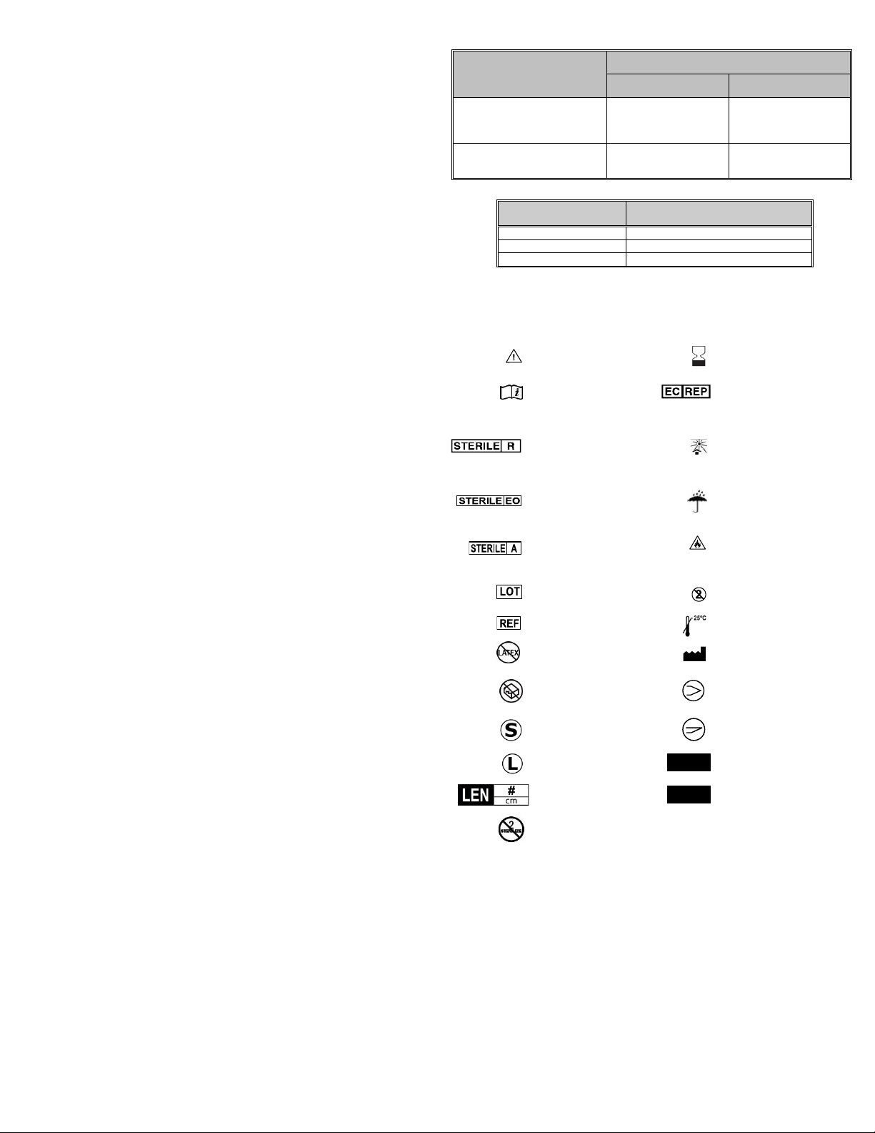
18
sorgfältig überwacht werden. Die Vorrichtung wird eingefahren, indem der
Ausfahrgriff entgegen dem Uhrzeigersinn gedreht wird.
xii) Das MLO unter Bildgebungsführung aus der Arbeitskanüle des StabiliT-
Einführbestecks entfernen.
xiii) Die Position der Arbeitskanüle des StabiliT-Einführbestecks in der Wirbelsäule
ist nach der Entfernung des MLO zu überwachen und falls erforderlich
anzupassen.
7) Die StabiliT-Applikationsspritze vorbereiten.
a) Den Absperrhahn von der Verpackung der StabiliT-Applikationsspritze entfernen.
b) Die StabiliT-Applikationsspritze an den Verlängerungsschlauch des
Buchsenanschlusses des Absperrhahns anschließen (gegenüber dem
Steckeranschluss).
c) Sicherstellen, dass der Stecker des Absperrhahns sich in geschlossener Position
befindet.
d) Den Kolben mit ausreichend Kraft vorschieben, um jegliche Luft aus der Spritze zu
entfernen.
e) Den Absperrhahn in steriles Wasser tauchen (oder in Kochsalzlösung).
f) Den Auslöser der StabiliT-Applikatorspritze zusammendrücken und den Griff
zurückziehen, um die Spritze mit Flüssigkeit zu füllen. Fortfahren, bis die Spritze
ganz gefüllt ist.
g) Die StabiliT-Applikationsspritze umdrehen, den Auslöser zusammendrücken und
den Kolben vorschieben, um jegliche verbleibende Luft in der Spritze und im
Verlängerungsschlauch zu entfernen.
h) Den Auslöser auf der StabiliT-Applikationsspritze zusammendrücken und ganz
zurückziehen, um steriles Wasser aufzuziehen (oder Kochsalzlösung).
Vorsicht: Untersuchen Sie den Schlauch und den Absperrhahn der StabiliT-
Applikationsspritze, um sicherzustellen, dass sich keine Luft im System befindet].
8) Die Systemkomponenten zusammenbauen
a) Eine Minute vor der Knochenzementabgabe (siehe Tabelle 1) die Filter- und
Trichterbaugruppe entfernen. Die Zementspritze von überschüssigem
Knochenzement reinigen und die Zementspritze ganz in die Sperrabgabekanüle
schrauben.
b) Die Hauptspritze vollständig in die Zementspritze schrauben.
Vorsicht: Vor dem Vorgang sicherstellen, dass die Hauptspritze GANZ auf der
Zementspritze verschraubt ist. Andernfalls sind Verletzungen des Benutzers oder
Funktionsstörungen des Geräts möglich.
c) Die StabiliT-Applikationsspritze an der Hauptspritze anbringen. Den Luer der
Hauptspritze sicher am Absperrhahn am Ende des Verlängerungsschlauchs der
StabiliT-Applikationsspritze anbringen.
Vorsicht: Nicht mit der Knochenzementabgabe beginnen, bevor die Sättigungs-
und Vorbereitungszeit abgelaufen ist (siehe Tabelle 1).
9) Zementabgabe
a) Vergewissern Sie sich, dass der Auslöser der StabiliT-Applikationsspritze gelöst ist,
um zu gewährleisten, dass der Kolben in seiner Position gesperrt ist.
b) Die LDC mit Knochenzement füllen, indem der Griff der StabiliT-Applikationsspritze
IM UHRZEIGERSINN gedreht wird. Sobald Knochenzement aus der LDC-Spitze
austritt, den Zementfluss durch Zusammendrücken des Auslösers auf der StabiliT-
Applikationsspritze stoppen. Den Auslöser loslassen, um den Kolben in der
zurückgezogenen Position zu sperren. Die LDC-Spitze säubern.
c) Unter Röntgendurchleuchtung die Arbeitskanüle stabilisieren und die LCD
einführen, bis das Drehrad den Luer der Arbeitskanüle berührt. Das LDC-Rädchen
drehen, um die LDC an der Arbeitskanüle anzubringen.
d) Wenn alles zur Abgabe des Knochenzements bereit ist, den Auslöser der StabiliT-
Applikationsspritze zusammendrücken und den Griff nach vorn drücken, bis
Widerstand zu spüren ist und den Auslöser loslassen. Unter
Röntgendurchleuchtung Knochenzement abgeben, indem der Griff IM
UHRZEIGERSINN gedreht wird.
e) Um die Abgabe von Knochenzement zu unterbrechen, den Auslöser der StabiliT-
Applikationsspritze zusammendrücken. Den Auslöser loslassen, um den Kolben in
der zurückgezogenen Position zu sperren. Um fortzufahren, den Auslöser
zusammendrücken und den Griff nach vorn drücken, bis Widerstand zu spüren ist,
dann den Auslöser loslassen. Weiter Knochenzement abgeben, indem der Griff IM
UHRZEIGERSINN gedreht wird.
Vorsicht: Um die Gewinde des Freigabegriffs zu schützen, muss das Messgerät
25 ATM oder weniger anzeigen, bevor der Schnellkopplungsmechanismus
verwendet wird, um den Fluss zu unterbrechen und den Druck abzulassen.
Vorsicht: Der Schnellkopplungsmechanismus wird aktiviert (am Klickgeräusch
erkennbar), wenn der Bediener den Höchstdruck für die StabiliT-Applikationsspritze
überschreitet. Sobald dies eintritt, kann der Schnellkopplungsmechanismus bei
niedrigeren Drücken bei nachfolgenden Versuchen der Druckerhöhung gelöst
werden.
Vorsicht: Nach Beendigung der Knochenzementabgabe die LCD innerhalb von
einer Minute von der Arbeitskanüle entfernen und sofort den Mandrin in die
Arbeitskanüle einsetzen und dort befestigen. Wird keine weitere Knochen-
zementabgabe benötigt, das Einführbesteck entfernen (Kanüle mit Mandrin).
Warnung: Das Entfernen der Arbeitskanüle sollte nur nach dem Einsetzen des
Mandrin durch Drehung und axiale Bewegung erfolgen. Die Arbeitskanüle NICHT
zur Seite hin verbiegen, da dies zu einer Verletzung des Patienten führen könnte.
Tabelle 1: Dauer der verschiedenen Aktivitäten bei unterschiedlichen
Umgebungstemperaturen
Aktivität
Ungefährer Gesamtzeitraum ab Einleitung
der Sättigung (in Minuten)
@ 18-19 °C
(65-67 °F)
@ 20-23 °C
(68-74 °F)
Sättigung und Vorbereitung
des Knochenzements
(Siehe IFU für
Knochenzement)
0-10 Minuten
0-5 Minuten
Knochenzementabgabe
10-45 Minuten
(35 Minuten
Arbeitszeit)
5-40 Minuten
(35 Minuten
Arbeitszeit)
Tabelle 2: Auswirkung der Umgebungstemperatur auf Zement
TemperaturºC (ºF)
Mindestaushärtungszeit (in
Minuten)
81 (27)
35
73 (23)
51
66 (19)
82
LAGERUNG UND HANDHABUNG
Vorsichtig handhaben. An einem sauberen, kühlen und trockenen Ort in der
Originalverpackung aufbewahren. Belastung durch extreme Temperaturen und Feuchtigkeit
vermeiden.
GLOSSAR DER SYMBOLE
Vorsicht
Zu verwenden bis
Die Gebrauchsanleitung
lesen
Autorisierter
Handelspartner in der
Europäischen
Gemeinschaft
Mit Bestrahlung
sterilisiert
(Applikationsinstrument
e, Osteotome und
Einführbesteck)
Vor Sonnenlicht schützen
Mit Ethylenoxid
sterilisiert
(Knochenzementpulver
& Applikationsspritze)
Vor Feuchtigkeit schützen
Unter Filtrierung
sterilisiert
(Knochenzementflüssigk
eit)
Entzündlich
Losnummer
Einwegsystem, NICHT
WIEDERVERWENDBAR
Bestellnummer
Bei einer Temperatur von
unter 25 °C lagern
Latexfrei
Hersteller
Inhalt bei beschädigter
oder geöffneter
Verpackung nicht
verwenden.
Diamantspitze
Kurz
Abgeschrägte Spitze
Lang
Kanülenmessgerät
Gerätelänge in
Zentimeter
Einführbesteck-
Messgerät/Sperrabagebka
nüle-Messgerät
Nicht erneut
sterilisieren
ANZ:
Anzahl
# G
# / # G
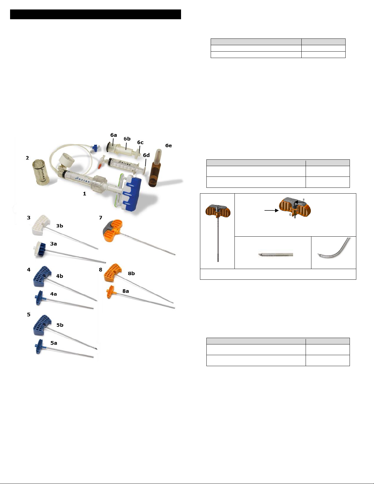
19
Σύστημα Σπονδυλικής Επαύξησης StabiliT®MX
(Για χρήση με το Οστικό Τσιμέντο StabiliT®)
Οδηγίες χρήσης (Ελληνικά) (EL)
Σημαντικές πληροφορίες – Διαβάστε πριν από τη χρήση
ΠΡΟΣΟΧΗ: Η Ομοσπονδιακή νομοθεσία (ΗΠΑ) περιορίζει την πώληση της συσκευής αυτής
από γιατρούς ή κατόπιν εντολής γιατρού.
ΕΝΔΕΙΞΕΙΣ
Το Σύστημα Σπονδυλικής Επαύξησης StabiliT® MX προορίζεται για διαδερμική τοποθέτηση του
οστικού τσιμέντου StabiliT® . Το οστικό τσιμέντο StabiliT® ενδείκνυται για την αντιμετώπιση
παθολογικών καταγμάτων των σπονδύλων μέσω σπονδυλοπλαστικής ή κυφοπλαστικής. Τα
επώδυνα συμπιεστικά κατάγματα των σπονδύλων μπορεί να προέλθουν από οστεοπόρωση,
καλοήθεις βλάβες (αιμαγγείωμα) και κακοήθεις βλάβες (μεταστατικός καρκίνος, μυέλωμα).
Ο Οστεοτόμος Μέσης Γραμμής Διαβάθμισης Οστικού Τσιμέντου VertecoR®, ο Οστεοτόμος Μέσης
Γραμμής (MLO) VertecoR®, ο Οστεοτόμος Ευθείας Γραμμής Διαβάθμισης Οστικού Τσιμέντου
VertecoR®3.0-11.5 και ο Οστεοτόμος Ευθείας Γραμμής (SLO) Διαβάθμισης Οστικού Τσιμέντου
VertecoR®3.0 προορίζονται για την απόξεση ή αφαίρεση πυρήνα οστού της σπονδυλικής
στήλης.
ΠΕΡΙΓΡΑΦΗ
Το Σύστημα Σπονδυλικής Επαύξησης StabiliT MX είναι ένα σύστημα για την ελεγχόμενη
τοποθέτηση οστικού τσιμέντου StabiliT κατά τη θεραπεία συμπιεστικών καταγμάτων των
σπονδύλων. Το Σύστημα Σπονδυλικής Επαύξησης StabiliT MX αποτελείται από οκτώ (8) στοιχεία
(Εικόνα 1).
Εικόνα 1. Σύστημα Σπονδυλικής Επαύξησης StabiliT MX
Σύριγγα Χορήγησης StabiliT (1) - Χρησιμοποιείται για τη χορήγηση οστικού τσιμέντου στο
σπονδυλικό σώμα.
Συσκευές Χορήγησης StabiliT (2, 3, 4) - Χρησιμοποιούνται για την πρόσβαση στο
σπονδυλικό σώμα και τη διευκόλυνση της χορήγησης οστικού τσιμέντου PMMA σε
ορθοπεδικές διαδικασίες, συμπεριλαμβανομένων αυτών που σχετίζονται με
σπονδυλοπλαστική και κυφοπλαστική.
oΚύρια σύριγγα (2)
oΣωληνίσκος τοποθέτησης με ασφάλεια (LDC) (3)
Σωληνίσκος (3α)
Στυλίσκος (3β)
oΔιάταξη Εισαγωγής StabiliT με στυλίσκο με ρομβοειδές άκρο (αρ. 4) - Η Διάταξη
Εισαγωγής StabiliT χρησιμοποιείται για διαδερμική πρόσβαση σε οστά. Η συσκευή
παρέχεται με ένα στυλίσκο με ρομβοειδές άκρο και με ένα σωληνίσκο. Ο σωληνίσκος
της διάταξης εισαγωγής έχει εξωτερική διάμετρο 3,6 mm. Για το μήκος της συσκευής,
βλ. το παρακάτω διάγραμμα.
Σωληνίσκος (4α)
Στυλίσκος (4β)
Διάταξη Εισαγωγής StabiliT με στυλίσκο με λοξοτμημένο άκρο (#5) σε ορισμένες
διευθετήσεις κιτ (για λεπτομέρειες, βλ. ετικέτα προϊόντων) – Η Διάταξη Εισαγωγής StabiliT με
λοξοτμημένο άκρο χρησιμοποιείται για διαδερμική πρόσβαση σε οστά. Η συσκευή παρέχεται
με ένα στυλίσκο με λοξοτμημένο άκρο και με ένα σωληνίσκο. Ο σωληνίσκος της διάταξης
εισαγωγής έχει εξωτερική διάμετρο 3,6 mm. Για το μήκος της συσκευής, βλ. το παρακάτω
διάγραμμα.
Σωληνίσκος (5α)
Στυλίσκος (5β)
Συσκευή
Ωφέλιμο μήκος
Διάταξη Εισαγωγής StabiliT 3.6-11.5
11 cm
Διάταξη Εισαγωγής StabiliT 3.6
13 cm
Οστικό Τσιμέντο StabiliT και σύστημα ανάμιξης κορεσμού (6) -
oΤο Οστικό Τσιμέντο StabiliT ενδείκνυται για τη θεραπεία παθολογικών καταγμάτων των
σπονδύλων με τη χρήση σπονδυλοπλαστικής ή κυφοπλαστικής. Τα επώδυνα
συμπιεστικά κατάγματα των σπονδύλων μπορεί να προέλθουν από οστεοπόρωση,
καλοήθεις βλάβες (αιμαγγείωμα) και κακοήθεις βλάβες (μεταστατικός καρκίνος,
μυέλωμα).
oΤο σύστημα ανάμιξης κορεσμού προορίζεται για την ανάμιξη του Οστικού Τσιμέντου
StabiliT.
Χοάνη (6α)
Σύριγγα τσιμέντου (6β)
Φίλτρο (6γ)
Σύριγγα με ασφάλεια (6δ)
Μονομερές (6ε)
Οστεοτόμος Μέσης Γραμμής Διαβάθμισης Οστικού Τσιμέντου (MLO) VertecoR (7) - Η
συσκευή MLO είναι ένας αποστειρωμένος οστεοτόμος μίας χρήσης που προορίζεται για την
απόξεση ή αφαίρεση πυρήνα οστού, για τη δημιουργία μιας περιοχής στην οποία μπορεί να
τοποθετηθεί οστικό τσιμέντο κατά τη θεραπεία συμπιεστικών καταγμάτων των σπονδύλων.
Πρέπει να χρησιμοποιείται μαζί με τη Διάταξη Εισαγωγής StabiliT. Ο άξονας έχει εξωτερική
διάμετρο 3,0 mm. Για τα ωφέλιμα μήκη, βλ. το παρακάτω διάγραμμα.
Συσκευή
Ωφέλιμο μήκος
Οστεοτόμος μέσης γραμμής διαβάθμισης
οστικού τσιμέντου 3.0-11.5
14,5 cm
Οστεοτόμος μέσης γραμμής διαβάθμισης
οστικού τσιμέντου 3.0
16,5 cm
A. MLO
B1. Η λαβή έκπτυξης είναι το λεπτό περιστρεφόμενο
τμήμα της λαβής του MLO. B2 Το βέλος κατεύθυνσης
δείχνει προς την κατεύθυνση του αρθρωτού άκρου
Γ. Μη εκπτυγμένο αρθρωτό άκρο
Δ. Εκπτυγμένο
αρθρωτό άκρο
Ο MLO (A) διαθέτει μια λαβή (B) η οποία περιλαμβάνει μια περιστρεφόμενη
λαβή έκπτυξης η οποία εκπτύσσει το αρθρωτό άκρο (Γ, Δ).
Οστεοτόμος Ευθείας Γραμμής (SLO) Διαβάθμισης Οστικού Τσιμέντου VertecoR (8) σε
ορισμένες διευθετήσεις κιτ (για λεπτομέρειες βλ. ετικέτα προϊόντων) - Η συσκευή SLO είναι
ένας αποστειρωμένος οστεοτόμος μίας χρήσης που προορίζεται για την απόξεση ή αφαίρεση
πυρήνα οστού, για τη δημιουργία μιας περιοχής στην οποία μπορεί να τοποθετηθεί οστικό
τσιμέντο κατά τη θεραπεία συμπιεστικών καταγμάτων των σπονδύλων και τη λήψη
δείγματος για βιοψία. Παρέχεται με ένα στυλίσκο με αμβλύ άκρο. Πρέπει να χρησιμοποιείται
μαζί με τη Διάταξη Εισαγωγής StabiliT. Ο άξονας έχει εξωτερική διάμετρο 3,0 mm. Για τα
ωφέλιμα μήκη, βλ. το παρακάτω διάγραμμα.
Σωληνίσκος (8α)
Στυλίσκος (8β)
Συσκευή
Ωφέλιμο μήκος
Οστεοτόμος Ευθείας Γραμμής Διαβάθμισης
Οστικού Τσιμέντου VertecoR 3.0-11.5
13,5 cm
Οστεοτόμος Ευθείας Γραμμής Διαβάθμισης
Οστικού Τσιμέντου VertecoR 3.0
15,5 cm
ΤΡΟΠΟΣ ΔΙΑΘΕΣΗΣ
Όλα τα στοιχεία παρέχονται αποστειρωμένα. Αυτές οι συσκευές προορίζονται για μία μόνο
χρήση. ΜΗΝ επαναποστειρώνετε ή/και ΜΗΝ επαναχρησιμοποιείτε. ΜΗΝ χρησιμοποιείτε εάν η
συσκευασία έχει ανοιχτεί ή υποστεί ζημιά και ενημερώστε τον κατασκευαστή.
ΑΝΤΕΝΔΕΙΞΕΙΣ
Η χρήση αυτού του προϊόντος αντενδείκνυται σε ασθενείς με διαταραχές πήξης ή σοβαρή
πνευμονική ανεπάρκεια.
Η χρήση αυτού του προϊόντος αντενδείκνυται σε ασθενείς με ενδοτικότητα στην οπίσθια
στήλη του σπονδυλικού σώματος ή των τοιχωμάτων των αυχένων των σπονδύλων.
Η χρήση του οστικού τσιμέντου PMMA αντενδείκνυται παρουσία ενεργής λοίμωξης ή ατελώς
θεραπευθείσας λοίμωξης στην περιοχή όπου πρόκειται να εφαρμοστεί το οστικό τσιμέντο.
Αυτό το προϊόν δεν πρέπει να χρησιμοποιείται σε ασθενείς με ευαισθησία σε οποιοδήποτε από
τα συστατικά του οστικού τσιμέντου ΡΜΜΑ.
ΠΡΟΕΙΔΟΠΟΙΗΣΕΙΣ
Διαβάστε προσεκτικά τις Οδηγίες Χρήσης κάθε συσκευής, συμπεριλαμβανομένου του
Οστικού Τσιμέντου StabiliT και του συστήματος ανάμιξης κορεσμού (εάν βρίσκονται σε
ξεχωριστές συσκευασίες ή μαζί με τις παρούσες Οδηγίες Χρήσης), πριν από τη χρήση. Για τη
διεξαγωγή διαδικασίας με χρήση του Συστήματος Σπονδυλικής Επαύξησης StabiliT MX πρέπει
Table of contents
Languages:
Popular Medical Equipment manuals by other brands


IceCure
IceCure FAP 7100000 Instructions for use

bort medical
bort medical Dr. Schütz ManuDisc quick guide

Jarven Health Care
Jarven Health Care OptiCell 4 PRO user guide

SoftGuards
SoftGuards MLE09065 quick start guide

MHC Medical Products
MHC Medical Products SureLife Clearwave user manual

Gate
Gate Mover Aqua 53-301 operating instructions