MEDIZS Smart RK11 User manual


1
IMPORTANT NOTICE
This product may malfunction due to electromagnetic waves caused by cellular
phone, transceivers, radio-controlled toys, and etc. Be sure to avoid having objects
such as, which affect this product, brought near the product.
The information in this publication has been carefully checked and is believed to be
entirely accurate at the time of publication. MEDIZS assumes no responsibility,
however, for possible errors or omissions, or for any consequences resulting from
the use of the information contained herein.
MEDIZS reserves the right to make changes in its products or product specifications
at any time and without prior notice, and is not required to update this
documentation to reflect such changes.
Operation Manual Ver 1.09 / 2015.10
ⓒ2011 MEDIZS Inc.
All rights are reserved.
Under copyright laws, this manual may not be copied, in whole or in part,
without the prior written consent of MEDIZS Inc.
94-10, Techno-2ro, Yuseong-gu, Daejeon,
305-509, Republic of Korea

2
Contents
1. Introduction and feature......................................................................................................................3
2. Safety information
2-1 Symbols marked on the Instrument ......................................................................................4
2-2 EU Countries .....................................................................................................................................4
2-3 General Safety Information .........................................................................................................5
3. Notes for using the instrument........................................................................................................ 7
4. Description
4-1 Front side of body ........................................................................................................................9
4-2 Back side of body........................................................................................................................10
4-3 Bottom side of body..................................................................................................................11
4-4 Operation Buttons & Wheel ...................................................................................................12
5. Installation and preparation.............................................................................................................12
6. Practicing by model eye.....................................................................................................................14
7. Measurement
7-1 REF mode (Refractometry mode)..........................................................................................18
7-2 KER mode (Keratometry mode).............................................................................................21
7-3 RK mode (Continuous Keratometry and Refractometry mode) ...............................22
7-4 PK mode (Peripheral Keratometry mode)..........................................................................23
7-5 CLBC mode (Contact Lens Base Curve mode).................................................................27
7-6 IOL measuring mode .................................................................................................................29
7-7 SIZE mode (Cornea Size measuring mode) ......................................................................30
8. Other modes
8-1 Result mode (Seeing measurement result screen)..........................................................32
8-2 Configure mode............................................................................................................................33
8-3 External Video Display ..............................................................................................................40
8-4 TARGET BRIGHTNESS ..................................................................................................................40
9. Self inspection and maintenance
9-1 Before calling Service Person ...............................................................................................41
9-2 Cleaning ..........................................................................................................................................42
9-3 When moving the Instrument................................................................................................42
9-4 Replacement of Paper ...............................................................................................................43
10. Service information ..............................................................................................................................44
11. Specifications...........................................................................................................................................45
12. Components.............................................................................................................................................46

3
1. Introduction and feature
RK 11 performs usual Refractometry and Keratometry. Also base curve of contact
lens can be measured with this instrument.
The main features of RK11 are as follows.
1. RK11 offers various measurement modes.
2. Because the RK11 covers a wide measurement range, from -30D to +22D, even
an examinee with strong myopia can be measured.
3. RK11 provides user-friendly environment by adopting smooth curved shape,
stylish color and user-centered design and user interface (GUI).
4. RK11 provides Height Auto Tracking.

4
2. Safety information
2-1 Symbols marked on the instrument
Symbol
Description
TYPE B EQUIPMENT
Protective earth (ground)
Alternating current
Attention, consult ACCOMPANYING DOCUMENTS
Off (power: disconnect to the mains)
On (power: connection to the mains)
Do not throw away the waste to inappropriate place
Manufacturer
Authorized Representative in the European community
Consult operating instructions
2-2 EU Countries
The following mark, the name & address of the EU Representative shows compliance of the
instrument with Directive 93/42/EEC.
EU Representative:
CALMED INVEST Kft.
1182 Budapest, Fiume utca 3., Budapest, Hungary

5
2-3 General safety information
If you see any warnings or cautions printed on the warning labels, follow
the safety instructions in this manual. Ignoring such cautions or warnings
while handling the product may result in injury or accident. Be sure to read
and fully understand the manual before using this product.
Keep this manual in easy-to-access place.
WARNING
This indicates a potentially hazardous situation which could results
in death or serious injury to you or others.
CAUTION
This indicates hazardous situations which may result in minor injury
to you or others, or may result in machine damage.
NOTE
This is used to emphasize essential information. Be sure to read this
information to avoid incorrect operation.
WARNING
Only operate the instrument with the power supply indicated on the
rating plate. Otherwise, it may result in fire or electric shock.
WARNING
Be sure to turn OFF the power switch before connecting or
disconnecting the cables. Also, do not handle them with wet
hands. Otherwise, you may get an electric shock that may result in
death or serious injury.
WARNING
Should any of the following occur, immediately turn OFF the
power switch, unplug the power cable from the AC outlet, and
contact the dealer or the agent who/where you purchase this
instrument.
▪When there is smoke, strange odor or abnormal sound.
▪When liquid has been spilled into the instrument or a metal
object has entered through an opening.
▪When the product has been dropped or its housing damaged.
WARNING
Never disassemble or modify this instrument because it may result
in fire or electric shock. Also, since this instrument incorporates
high-voltage parts and other hazardous parts, touching them may
cause death or serious injury.

6
WARNING
Do not Keep way the place where the temperatures very much.
CAUTION
This instrument is shipped with a grounding type power cable. To
reduce the risk of electric shock, always plug the cable into a
grounded power outlet.
CAUTION
Wipe the forehead rest with ethanol or glutaraldehyde solution to
disinfect it each time a different examinee uses it, in order to prevent
infection.
CAUTION
Ensure that the examinee has not placed his/her hand or fingers
under the chin rest. Otherwise, hand or fingers may be hurt.
1. An exposure to the direct sunlight or very bright indoor lights may influence
on the result of accurate measurement. Recommend to use in appropriate
test room.
2. A sudden heating of the room in cold areas will cause condensation on the
protective glass in the monitor screen and on optical parts inside the
instrument. In this case, just wait until condensation disappears before
performing measurement.
3. This instrument is used with accessories from MEDIZS. If consumer would like
to use the accessories from other manufactures, safety of accessories should
be verified and identified by manufacturer or by MEDIZS.
4. Operation manual should be keep at the place where the user can easily access.
5. This instrument can be installed and maintained by the person who have
completed training or education course.
6. When moving this instrument, please keep vibration or impact away from the
equipment. It can bring some damage inside or outside of the instrument.
Please carefully handle the instrument.
7. When moving equipment, fix the stage, always keep power off, and then lift
the bottom of the unit with both hands.
8. To connect this instrument with other relevant equipment, consult with the
dealer about the way to make it.

7
9. In case there is smoke, strange odor or noise on working, disconnect the power
supply and consult the dealer.
10. Don’t use organic solution such as alcohol, thinner, benzene, etc. to clean the
surface of this instrument. It may damage the instrument.
11. Do not disassemble or modify this instrument.
12. If you are not using this instrument a long time, disconnect the power supply
and protect the unit with dust cover.
13. Do not pull on the cable of equipment.
14. Please check the condition of unit appearance before using the instrument.
3. Notes for using the instrument
3-1 Before use
1. Stand 40 minutes and get it worked if it is stored in low temperature place.
If the inside temperate of instrument is too low, it may cause on ERROR or
inaccurate measurement.
2. A sudden heating of the room in cold areas will cause condensation on the
protective glass in the monitor screen and on optical parts inside the
instrument. In this case, just wait until condensation disappears before
performing measurement.
3. Check printing papers are ready.
4. Check the condition of unit appearance and operation such as chin rest
working.
5. Check horizontality of unit.
6. Remove dusts, especially on the measurement window. It may cause on
ERROR or inaccurate measurement.
3-2 When you use
1. Do not make dirty, such as fingerprint, on the lens of measurement window.
It may cause on ERROR or inaccurate measurement.
2. Do not put other object on this equipment.
3. If you want to keep measurement result for a long time, make a copy of it.

8
Printed data on thermal paper may be disappeared after a long time.
3-3 After use
1. Cover up the instrument with dust cover and unplug if do not use long.
2. If the measurement window is not clean, wipe it with soft and dry cloth
carefully to avoid any scratch.
3. When moving this instrument, please keep vibration or impact away from the
equipment. It can bring some damage inside or outside of the instrument.
3-4 Storage space
1. Not humid place and not in the vicinity of water.
2. Not dusty and not in the vicinity of filthy place with salt or sulphur.
3. Not in the vicinity of vibration or shock.
4. Plain place.
5. Not in the vicinity of direct sunlight.

9
4. Description
4-1 Front side of body
[Fig.1] Front side of body
Name
Description
①Monitor
Monitor that displays Measurement
②Operation Buttons & Wheel
There are function keys
③Measure Button / Body Wheel
Press this button for measurement.
And Regulating height of Body
④Operation Lever
It adjust the main body forward, backward, right side
and left side. (for adjusting the focus)
⑤Chinrest Up/Down Buttons
Regulating height of chin rest
⑥Power Switch
Switch for turning power ON and OFF.
⑦Stage Holing Lever
Holds the movement of stage
⑧Printer
Print the measured result
CAUTION
Ensure that the examinee has not placed his/her hand or fingers under
the chin rest. Otherwise, hand or fingers may be hurt.
⑧
①
②
③
④
⑤
⑥
⑦
③
④
⑤
⑥
⑦
④
⑤
⑥
⑦
⑥
⑦
⑤
⑦
⑦

10
CAUTION
Wipe the forehead rest with ethanol or glutaraldehyde solution
to disinfect it each time a different examinee uses it, in order to
prevent infection.
WARNING
Be sure to turn OFF the power switch before connecting or
Disconnecting the cables. Also, do not handle them with wet hands.
Otherwise, you may get an electric shock that may result in death or
serious injury.
4-2 Back side of body
[Fig.2] Back side of body
Name
Description
①Headrest
Place the examinee’s chin on the rest.
②Measurement Window
Window for the examinee to look at for
measurement
③Chinrest
Place the examinee’s chin on the rest.
④Height lining mark
Lining up eye level of patient by regulating chin rest
①
②
③
④
11
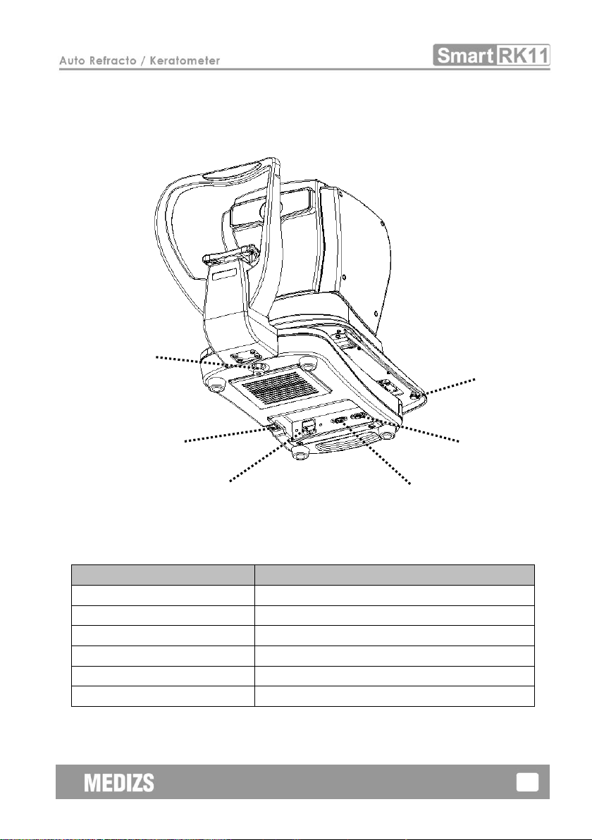
4-3 Bottom side of body
[Fig.3] Bottom side of body
Name
Description
①Stage Clamping Bolt
Makes the system stage fixed
②Power Switch
Switch for turning power ON and OFF
③Power IN LET
Power IN LET
④RS-232 Connector
Connect with external equipment
⑤EXT Video
Connect with external Video equipment.
⑥Stage Fixing Knob
Makes the system stage fixed
②
①
③
④
⑤
⑥
⑥
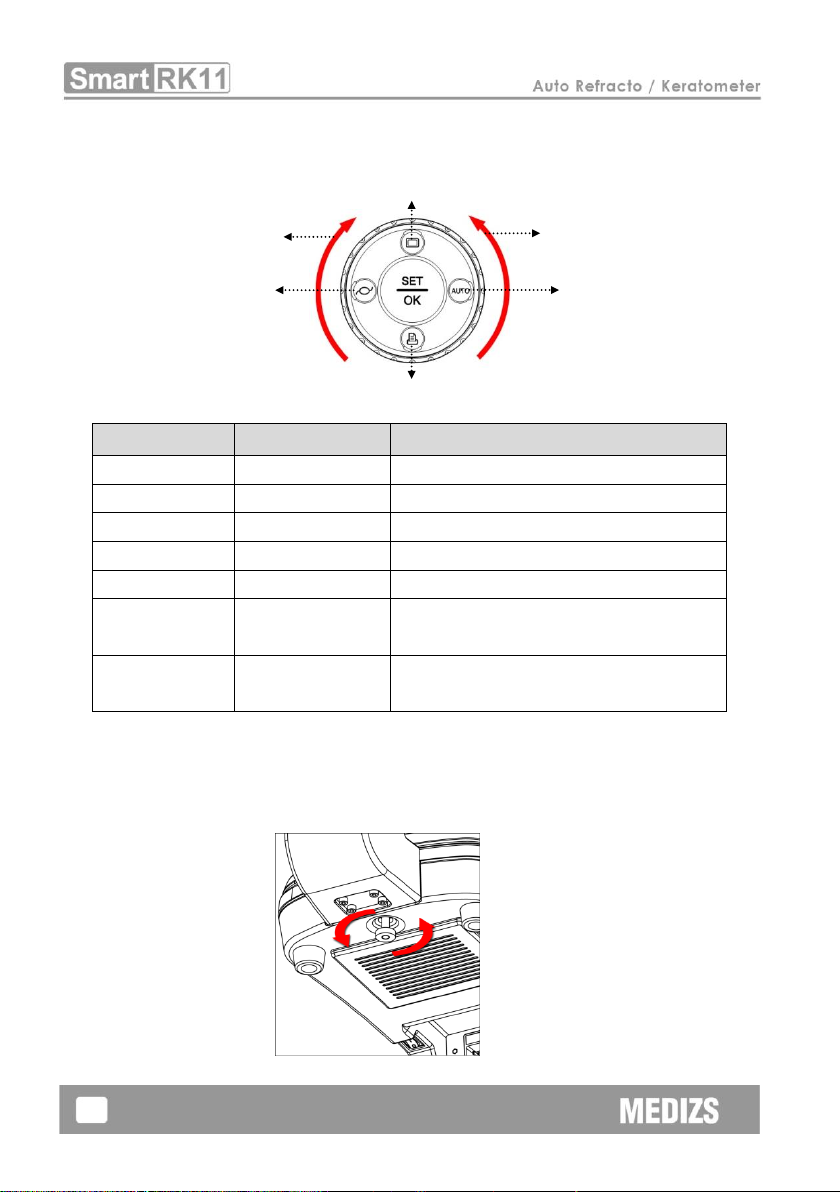
12
4-4 Operation Buttons & Wheel
Function of each button could be changed in certain mode. Please refer to the each
mode for details.
[Fig.4] Operation Buttons & Wheel
KEY
Main Function
Description
SET/OK
Configure
Operate Configure mode
LEFT
IOL
IOL mode ON/OFF
RIGHT
Auto/Manual
Select auto/manual measurement
UP
Result
Display measurement result
DOWN
Print
Print measurement result
WHEEL_LEFT
Mode Select
Select measurement mode
(Rotate the wheel counterclockwise)
WHEEL_RIGHT
Mode Select
Select measurement mode
(Rotate the wheel clockwise)
5. Installation and preparation
5-1 Unfixing the stage
Put RK11 on the table.
[Fig.5] Unfixing the stage
UP
RIGHT
WHEEL_LEFT
WHEEL_RIGHT
LEFT
DOWN

13
Rotate the stage clamping bolt located in the bottom of body counterclock-
wise and release. [Fig.5]
[Fig.6]
Rotate the stage holding lever to ‘UNFIXING’ direction. [Fig.6]
[Fig. 7]
push the stage to right side and then fasten the stage fixing knob by rotating
it clockwise. and do the same on left side. [Fig.7]
Check whether stage is moving freely
5-2 Connecting the power cable
Connecting the power cable to the connector on the bottom of main body.
Plug into AC outlet after switch off the instrument.
5-3 Putting rest papers (Refer to 9-4 Replacement of paper)
Pick out both holding pins on chin rest.
Insert both pins into holes on chin rest papers and stick it on chin rest.
5-4 Engage printing papers
Refer to 9-4 Replacement of paper.

14
5-5 Check setting
Please check the information such as VD, CYL format, SPH/CYL step, VD form
KER unit, KER index, date, etc on the measure screen and setting mode.
5-6 To connect with other equipment
This equipment is able to transfer test results other equipments. Consult with
the dealer for details.
6. Practicing by model eye
Practice measurement by using the model eye offered with RK11.
[Fig. 8]
6-1 Turn on the power
6-2 Set the model eye on
Align the holes on the base of the model eye with the holes on the chin
rest and then insert pins.
6-3 Release stage lock
Rotate the stage holding lever to ‘UNFIXING’ direction. (Refer to [Fig.6])
6-4 Mode selection
Choose REF or R/K mode by rotating the Operation Buttons& Wheel of
front body.
(Refer to 4-4Operation Buttons& Wheel)
WARNING
Be sure to turn OFF the power switch before connecting or disconnecting
the cables. Also, do not handle them with wet hands. Otherwise, you may
get an electric shock that may result in death or serious injury.
Model eye
Fix Pin
Measurement window

15
6-5 Adjust the height and focus on the model eye
1. Adjust the height of the model eye. (Support the height auto tracking.)
Adjust the height of the model eye to match with measurement window by
using chinrest up/down button.
By looking at focusing circle, turn the Body Wheel up or down aims to the
center, RK11 does height auto tracking.
※Operation the Body wheel ※
-Turning up & down the Body Wheel : the fine-tuning height of main
body.
-Turning up & down by pressing the Body Wheel : Lifting up & down
the height of the main body quickly.
<The limited point of the main body movement>
-Red ‘X’mark& Limit sign: Using Body Wheel cannot raise or lower the
main body.
2. Adjust the Focus on ring of the model eye
<Turn the Body wheel>
<Turn by pressing the Body Wheel>

16
Move the Operation Lever to arrow direction (right side or left side)
Move the Operation Lever backward and forward to find the focus of ring.
Three colors of circles appear on the screen. When circle is yellow,
it means focused, orange and white circles mean defocused.
6-6 Measurement
Manual measurement
①Press the Measure Button after adjust the position and focus on the model
eye.
②Measurement result is displayed on the screen. If some other message is
displayed, repeat the procedure 6-5Adjust the height and focus on the
model eye and measure again.
③Check whether Diopter value is correct or not. Diopter value is marked on
the bottom of the model eye.
Automatic measurement
①Press the Auto/Manual (RIGHT) button. (Refer to 4-4)
②Adjust the position and focus on the model eye.
③Automatic shooting begins when it is well focused.
(When focus indicator circle is yellow, it means focused.)
NOTE
Please set STEP to 0.12 for Validation of Model eye.
Because label value of Model eye is result at STEP 0.12.
If you have set STEP to 0.25, the measurement result of Model eye
may be higher or lower than label value.

17
6-7 Print
Pressing the Print (DOWN) button, printing on the paper.
NOTE
After printing, former measurement results will be cleared automatically
when staring next measurement.
NOTE
Record on thermal paper can be spoiled by heat. And Printed data on
paper will be disappeared as time goes by.If the result should be kept in
long period, please copy the result.
<Example Printer>

18
7. Measurement
7-1 REF mode
Refractometry can be performed on REF mode.
▣Operation Buttons & Wheel functions in REF mode
KEY
Function
Description
SET/OK
Configure
Operate Configure mode
LEFT
IOL
IOL mode ON/OFF
RIGHT
Auto/Manual
Select auto/manual measurement
UP
Result
Display measurement result
DOWN
Print
Print measurement result
WHEEL_LEFT
Mode Select
Select measurement mode
WHEEL_RIGHT
Mode Select
Select measurement mode
1. Rotate the Operation Buttons & Wheel until REF mode is displayed on the
screen.
2. Check whether required options (VD, STEP, CYL and etc.) were set properly.
3. Adjusting the height of examinee’s eye
By using the Chinrest Up/Down button or the Body Wheel button of control

19
lever, adjust the height until examinee’s eye is aligned with the mark on side
of head rest.
CAUTION
Keep hand or fingers out of under chin rest.
Could damage and injured.
4. Positioning and Focusing
Move control lever (to left/right side) to make center of examinee’s pupil
(bright dot) locate in the targeting mark
By moving the Operation Lever (to front/back side), focus to get clear mire
ring mark.
In this procedure, RK11 analyze the focusing condition and display the level
of focus.
Please, refer to 6-5.
5. Measurement
Manual measurement mode (MANU mode)
①Press the Measure Button.
②After finishing measurement, result is displayed on bottom of screen.
NOTE
If measurement is failed with ‘TRY AGAIN’message, perform the
measurement 1 more time. Regarding description of each message,
please refer to the ‘section 9-1’.
Automatic measurement mode (AUTO mode)
①Press Auto/Manual (RIGHT) button until Auto Icon is displayed.
②When the focus circle is yellow, RK-11 will measure automatically and
continuously by setting repeat count.
Table of contents
Other MEDIZS Medical Equipment manuals


Popular Medical Equipment manuals by other brands


Getinge
Getinge Arjohuntleigh Nimbus 3 Professional Instructions for use

Mettler Electronics
Mettler Electronics Sonicator 730 Maintenance manual

Pressalit Care
Pressalit Care R1100 Mounting instruction

Denas MS
Denas MS DENAS-T operating manual

bort medical
bort medical ActiveColor quick guide

AccuVein
AccuVein AV400 user manual


