Meritor Wabco OnLane User manual

TP-15110
Issued 07-15
Installation Guide
OnLane™ Lane Departure
Warning (LDW) System
Installation Guide
Freightliner M2 Only
Con-way
TP-15110Issued 07-151 Technical Bulletin
Hazard Alert Messages
Read and observe all Warning and Caution hazard alert messages in
this publication. They provide information that can help prevent
serious personal injury, damage to components, or both.
WARNING
To prevent serious eye injury, always wear safe eye protection
when you perform vehicle maintenance or service.
Park the vehicle on a level surface. Block the wheels to
prevent the vehicle from moving. Support the vehicle with
safety stands. Do not work under a vehicle supported only by
jacks. Jacks can slip and fall over. Serious personal injury and
damage to components can result.
How to Obtain Additional Maintenance,
Service and Product Information
Refer to Maintenance Manual MM-1291, OnLane™ Lane Departure
Warning System; and User Guide SP-1335, OnLane™ Driver Tips. If
you have any questions about the material covered in these
publications, or for more information about the Meritor WABCO
product line, please contact the Meritor OnTrac™ Customer Call
Center at 866-OnTrac1 (668-7221) or visit our website:
meritorwabco.com
How to Obtain Parts and Kits
Contact Meritor’s Commercial Vehicle Aftermarket at
888-725-9355.
Kit Parts List
Locate and verify that the kit is complete prior to beginning the
installation of this kit.
앫OnLane™ bracket
앫OnLane™ camera module
앫OnLane™ switch
앫Set of 2 audio switches
앫Wiring harness
앫Hardware kit
앫MCS-1411 installation document
Description
OnLane™ Lane Departure Warning (LDW) System with SafeTraK
technology by Takata is a camera-based warning system that
utilizes a camera mounted near the top center of the vehicle’s
windshield to monitor and calculate the vehicle’s position within the
lane. When OnLane™ detects the vehicle crossing lane markings
without the turn signal being activated, the system sounds an
audible warning through a set of speakers. OnLane™ identifies
intentional lane changes by monitoring the turn signals, brake
switch and vehicle speed.
The following conditions may impact system performance:
앫Dirty or damaged windshield
앫Poor lighting conditions caused by inoperable headlamp(s) or
severe road glare
앫Poor weather conditions such as snow, ice, heavy fog or heavy
rain
앫Poor pavement conditions such as broken road surface, ice,
snow, sand, dirt or gravel covering the road surface
앫Missing, worn, faded, damaged or covered lane markers
When the system cannot provide assistance, the vehicle’s amber
indicator is turned ON. The system resumes normal operation when
the environmental factors causing the interference are resolved and
the amber indicator will turn OFF.
SB-10058336-5948
TP-15110
Issued 07-15 (16579)
Page 2 Copyright Meritor, Inc., 2015 Printed in USA
Installation Procedures
Camera and Bracket Installation
The procedure for installing a new OnLane™ system will vary
depending on the vehicle in which the unit is being installed. Each
vehicle may have slightly different routing and wiring requirements.
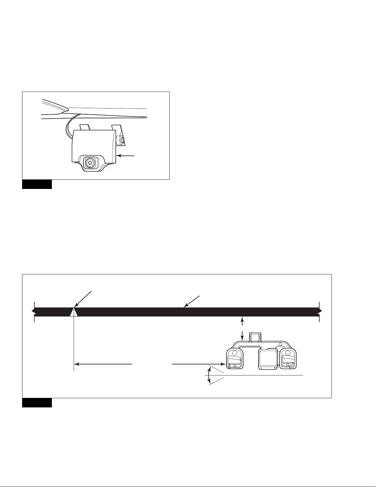
Figure 1.
Figure 1
Before securing the bracket to the windshield, note that the
locations of the mounting screws on the bracket are not tapped. We
recommend that you install the bracket to the camera module
before installing it in the vehicle. Use the self-tapping mounting
screws of the camera module to start the threads for the mounting
screws on the bracket. This action will allow for easier installation of
the camera module to the bracket, once the bracket is installed to
the windshield. Unscrew the bracket from the camera module
before you begin installing the bracket to the windshield.
The OnLane™ system should only be installed on a windshield
when the glass temperature is within the recommended range
between 70-100°F (21-37°C). Do not apply the bracket if the
windshield temperature is below 60°F (15°C).
1. Loosen the headliner and A-pillar trim panels as outlined in the
vehicle service manual to allow room to route the wiring behind
the header panel and down the A-pillar.
2. Clean the windshield mounting surface with IPA wipe (50/50
mix of isopropyl alcohol and water) or equivalent cleaner.
3. Allow the mounting surface to dry completely before
proceeding to the next step. The windshield surface must be
free of all oil, moisture and dirt for correct mounting bracket
adhesion.
NOTE: To download mounting bracket installation templates,
visit the OnLane™ literature web page at meritorwabco.com.
The templates must be printed to actual size (11x17
paper); any modification to the template’s size will result
in an incorrect installation of your system.
4. Align the template so that the markings on the template are
square to the centerline markings and the frit/trim line
markings at the top of the windshield. Figure 2. The template
shown is an example only.
Figure 2
Figure 1
4012047a
CAMERA
MODULE
Figure 2
4011169b
WINDSHIELD
CENTERLINE
MARKER
(EXAMPLE
TEMPLATE ONLY)
Install bracket so the bottom
surface of camera is level ±1.5"
when truck is parked on level surface.
Black trim at top of windshield.
NOTE:This line may not be straight or level.
OnLane™ Bracket:
P/N 000 000 000 0
XX MM ± X MM
35 MM ± 5 MM
TP-15110
(16579) Issued 07-15
Printed in USA Copyright Meritor, Inc., 2015 Page 3
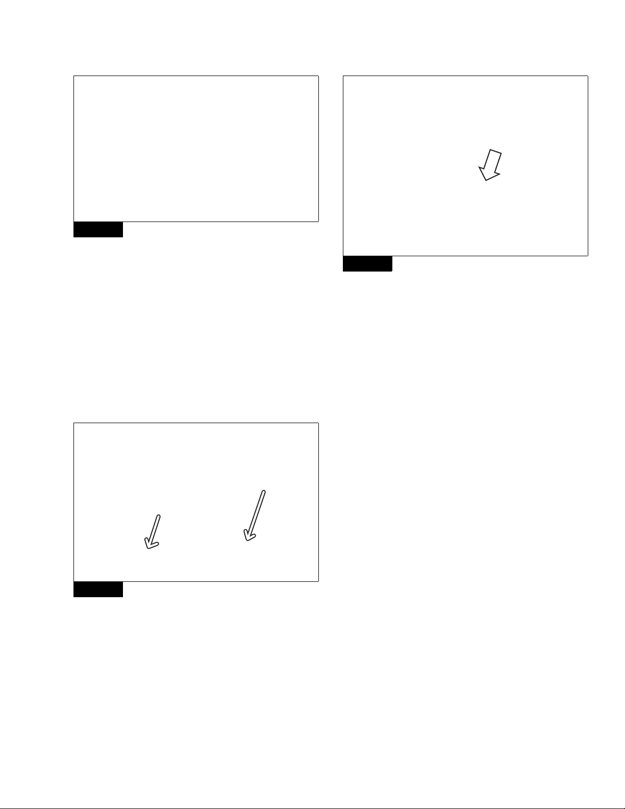
5. Remove the liners from the adhesive pads on the bracket.
Figure 3.
Figure 3
6. Hold the bottom of the bracket slightly away from the glass and
align the top of the bracket to the top of the template cutout.
7. Bring the bottom of the bracket adhesive pads into contact with
the glass and press the bracket firmly against the glass.
Maintain a minimum of 45 pounds of force for 30 seconds.
Wait 15-30 minutes for the mounting bracket adhesive to set.
8. Remove the yellow lens cap from the new LDW unit and
position the LDW unit onto the mounting bracket in a slightly
swung up position to align the upper tab. Align the two lower
tabs on the LDW unit by rotating the unit downward with the
lower tabs on the mounting bracket. Figure 4.
Figure 4
9. Install the two T15 torx head screws holding the LDW to the
mounting bracket. Tighten the screws to 2.5 +/- 0.4 N폷m
(22 +/- 3.5 ft-lb). DO NOT OVERTIGHTEN. @
OnLane™ Switch Installation
1. Locate a blank opening in the dashboard to accommodate the
OnLane™ switch (rocker switch). If one is not available, make
an opening in the dash to accommodate the switch.
2. Pull the switch connector to the back of the opening and
connect to the switch. Figure 5.
Figure 5
OnLane™ Audio Switch Installation
1. Identify the location in the truck where the OnLane™ audio
switches will be mounted (under the dash near each speaker).
Break the connection to the speakers. Wire the connectors in
the kit.
2. Route OnLane™ wires and ground. Plug the new connector
into the switch (extend the high/low and ground). This step
needs to be done for both the driver and passenger side
speakers.
3. Connect to the J1939 network and using ServiceLink, access
the Bulk Head Module. Add the following two features:
앫26-01048-001 (turn signal)
앫26-01028-002 (brake lamp)
4. Use the CAN to verify the installation.
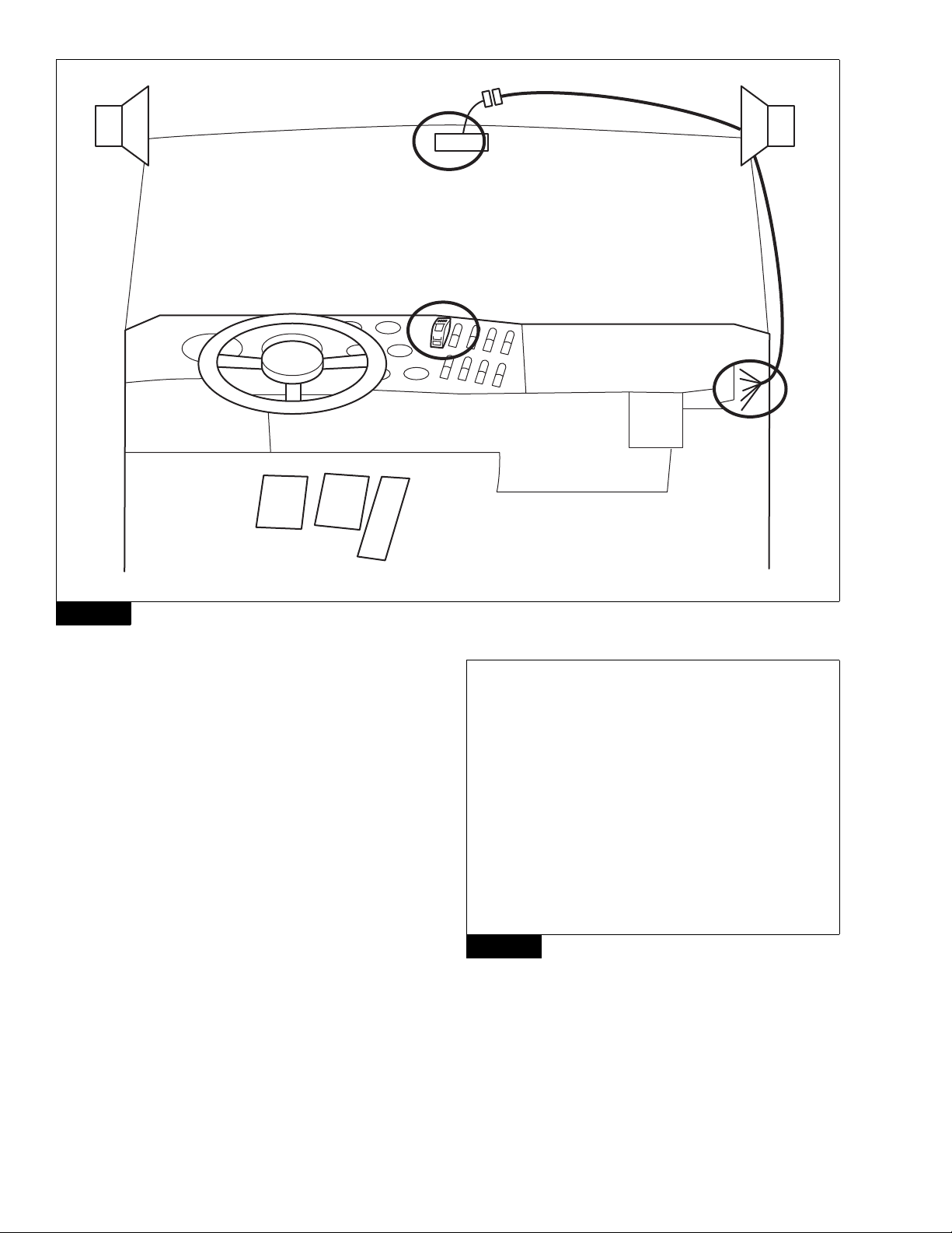
OnLane™ Wiring Harness Installation
1. Install the system wiring harness as shown. Make sure that you
do not pinch or cut the cables or wiring during installation of
the harness and trim panel or trim panel attaching screws.
Figure 6.
Use zip ties or straps as necessary to secure the harness to
prevent movement that may cause vibrations or compromise
harness integrity. Be careful to ensure that the wiring harness
is clear of all screw locations, including headliner and visor
locations. This prevents intrusions that may affect the integrity
of the wiring harness.
Most connections to the vehicle wiring are made on the
passenger side of the vehicle, so routing the wiring harness to
the passenger side A-pillar is recommended.
Figure 3
Figure 4
4010120a
4010121a
Figure 5
OnLane™ SWITCH
4012048a
TP-15110
Issued 07-15 (16579)
Page 4 Copyright Meritor, Inc., 2015 Printed in USA
Figure 6
2. Route the camera harness up the A-pillar and along the vehicle
headliner. Make sure that enough harness is present to allow
connect/disconnect of the camera connector without stressing
the harness or the connector.
3. Tuck the camera harness inside the headliner to mate with the
wiring harness connector from the A-pillar.
4. Route the OnLane™ switch connector behind the dash to the
desired location for the switch. If there is no opening on the
dash panel that can accommodate the switch, one should be
made. Figure 7.
Figure 7
5. The remaining wires can be routed under the instrument panel
for connection to the vehicle wiring. Figure 8.
Figure 6
4010130a
1
3
4
2
+
–
+
–
Figure 7
CONNECTOR ROUTED BEHIND THE DASH PANEL
4012049a

TP-15110
(16579) Issued 07-15
Printed in USA Copyright Meritor, Inc., 2015 Page 5
Figure 8
Connect the Wiring Harness to the Vehicle
Wiring
CAUTION
Disconnect vehicle battery before proceeding.
The installation package includes a wiring harness that must be
connected to the vehicle wiring. Brake and turn signal inputs must
provide a transition from 0V to +12VDC when the turn signal and
brake lights are activated.
1. Assemble the OEM truck wiring diagrams and the OEM truck
service/repair manual information necessary to correctly route
the wire harness into the headliner and behind the dashboard
and to locate and identify all circuits involved.
2. Connect +12VDC to a switched ignition power source that is
only powered when vehicle ignition is on to avoid draining the
vehicle battery.
3. Securely connect the wire harness connector to the OnLane™
module and switch. BE CAREFUL NOT TO PINCH OR DAMAGE
WIRES DURING ROUTING. Ensure that you do not hold the
camera away from the cable so you do not pull the wires inside
the camera.
4. Splice the flying leads from the harness to the various circuits
of the vehicle harness. Always follow the correct circuit splicing
procedures as outlined in the OEM truck service/repair manual.
The seven flying leads listed may not all be required. Consult
the installation information for your particular vehicle
application, or contact Customer Service.
앫Red – 12VDC Ignition power
앫Black – Vehicle ground
앫Green – J1939 CAN low
앫Yellow – J1939 CAN high
5. After wiring is complete, cut and tape off any of the unused
flying leads of the OnLane™ wiring harness.
Replace the headliner and any trim that may have been
removed during installation.
Verifying Correct System Operation
Confirm that the OnLane™ System is installed and operating
correctly by verifying the following.
앫When the vehicle ignition is turned on, the system issues a trial
warning tone from each speaker (left then right) and illuminates
the green and amber lights on the OnLane™ switch.
앫When the vehicle has reached approximately 42 mph (67.6 kph)
on a well-marked road, the amber LDW Not Available indicator
goes out, indicating the system is tracking and ready to issue
warnings.
앫The system does not issue warnings when the brakes are
applied or either turn signal is activated.
앫The operator can silence any alerts for 10-15 minutes
(depending on OEM settings) by pressing the OnLane™ switch.
Pressing the switch again should clear the mute mode and allow
warning alerts to sound.
앫Verify continuity and correct circuit function by performing the
Circuit Mode test.
OnLane™ Circuit Mode Test
1. Turn ignition key to power-up cab. During start up, the amber
LDW Not Available indicator and green LDW Enabled indicator
on the OnLane™ rocker switch are turned on.
2. Wait for the audible start-up tones to complete. If the indicators
do not light or there are no start-up tones, check the
OnLane™ power and ground connections, the switch
connections and the speaker connections.
3. Enter test mode by depressing the OnLane™ rocker switch at
least seven times within two seconds after the audible start-up
tones are complete. The system indicates that it is in test mode
by giving a short tone through the left speaker followed by one
through the right speaker. In a single speaker system, both
tones come through that speaker. While in test mode, the
green LDW Enabled indicator is turned off and the amber LDW
Not Available indicator flashes.
This test mode times out in 10 minutes. Turning off the vehicle
also causes the test mode to close.
If the amber LDW Not Available indicator is ON and the green
LDW Enabled indicator is OFF, this indicates that a system fault
is present. The system identifies the fault by flashing the green
LDW Enabled indicator.
Figure 8
WIRES ROUTED UNDER INSTRUMENT PANEL TO VEHICLE WIRING
4012051a

Information contained in this publication was in effect at the time the publication was approved for printing and is subject to
change without notice or liability. Meritor WABCO reserves the right to revise the information presented or to discontinue the
production of parts described at any time.
Copyright 2015 TP-15110
Meritor, Inc. Issued 07-15
All Rights Reserved Printed in USA (16579)
Meritor WABCO Vehicle Control Systems
2135 West Maple Road
Troy, MI 48084-7121 USA
866-OnTrac1 (668-7221)
meritorwabco.com
If the green indicator flashes, and the brake is not being
applied during test mode, it is identifying a fault.
4. Briefly activate the left turn signal and verify that a tone is
heard through the left speaker and the green LDW Enabled
indicator flashes. If a warning tone is not heard, check the left
turn signal connection.
5. Briefly activate the right turn signal and verify that a tone is
heard through the right speaker and the green LDW Enabled
indicator flashes. If a warning tone is not heard, check the right
turn signal connection.
6. Activate the brake and verify that the green LDW Enabled
indicator is turned on. If it is not turned on, check the brake
connection.
7. Turn the ignition key off to power down and exit the test mode.
If the self tests have not completed successfully, the vehicle’s
green indicator begins to flash to identify the fault.
OnLane™ Test Mode Faults
Read the fault code by counting the series of green LDW Enabled
indicator flashes. For example, if the fault code is 2, 3, the system
will flash ON two times for the first digit 2, pause for 3 seconds and
then flash ON 3 more times for the second digit 3, to indicate a 2, 3
fault code.
When the code display is complete, the green LDW Enabled
indicator switches OFF.
Redisplay the fault code by pressing and releasing the OnLane™
switch one time or connecting with TOOLBOX™ 11 (or later version)
software. Refer to the fault codes in the OnLane™ Maintenance
Manual MM-1291.
Table of contents
Other Meritor Wabco Automobile Accessories manuals

Popular Automobile Accessories manuals by other brands


ULTIMATE SPEED
ULTIMATE SPEED 279746 Assembly and Safety Advice

SSV Works
SSV Works DF-F65 manual

ULTIMATE SPEED
ULTIMATE SPEED CARBON Assembly and Safety Advice

Witter
Witter F174 Fitting instructions

WeatherTech
WeatherTech No-Drill installation instructions

TAUBENREUTHER
TAUBENREUTHER 1-336050 Installation instruction