Meriva MX3 User manual
User Manual
For
MX3 MDVR
Mobile Digital Video Recorder

Notice
The information in this manual was current when published. The manufacturer reserves the right to revise
and improve its products. All specifications are therefore subject to change without any notice.
The purpose of this manual is to kindly aid the user for the operation for our MDVR. The user should have
a basic understanding of computer operation and basic knowledge of how to connect peripherals and
make some settings.
Copyright
Under copyright laws, the content of this manual may not be copied, photocopied, reproduced, translated
or reduced to any electronic medium or machine- readable form, in whole or in part, without prior written
consent of Meriva.

Guarantee & Warnings
1)
Electrical Apparatus Safety
All installation and operation should comply with local electrical safety norms.
2)
Transportation
In the process of transportation, storage and installation, please avoid heavy stress, violent vibration,
impact and water splashing.
3)
Installation
Install the equipment in accordance with the requirements, handle carefully. Do not heavily press the
equipment before the MDVR installation is finished.
4)
Requirements on Engineers & Technicians
All the work of checking and maintenance should be done by qualified technicians and engineers. We
do not undertake any responsibility caused by unauthorized modifications.
5)
Requirements on Environment
The equipment should be installed and stored in a cool and dry place, away from direct sunlight,
flammable or explosive substances, etc. Keep gaps not less than 3cm around the device to facilitate
ventilation for cooling.
6)
Accessories
Make sure to use accessories from the manufacturer recommended in the attachment.
Insulate circuit ground and metal shell for all the peripherals.
Before installation, please open the package and ensure that all parts are included.
If there are any problems, please contact us as soon as possible.

1.
Product Characteristics
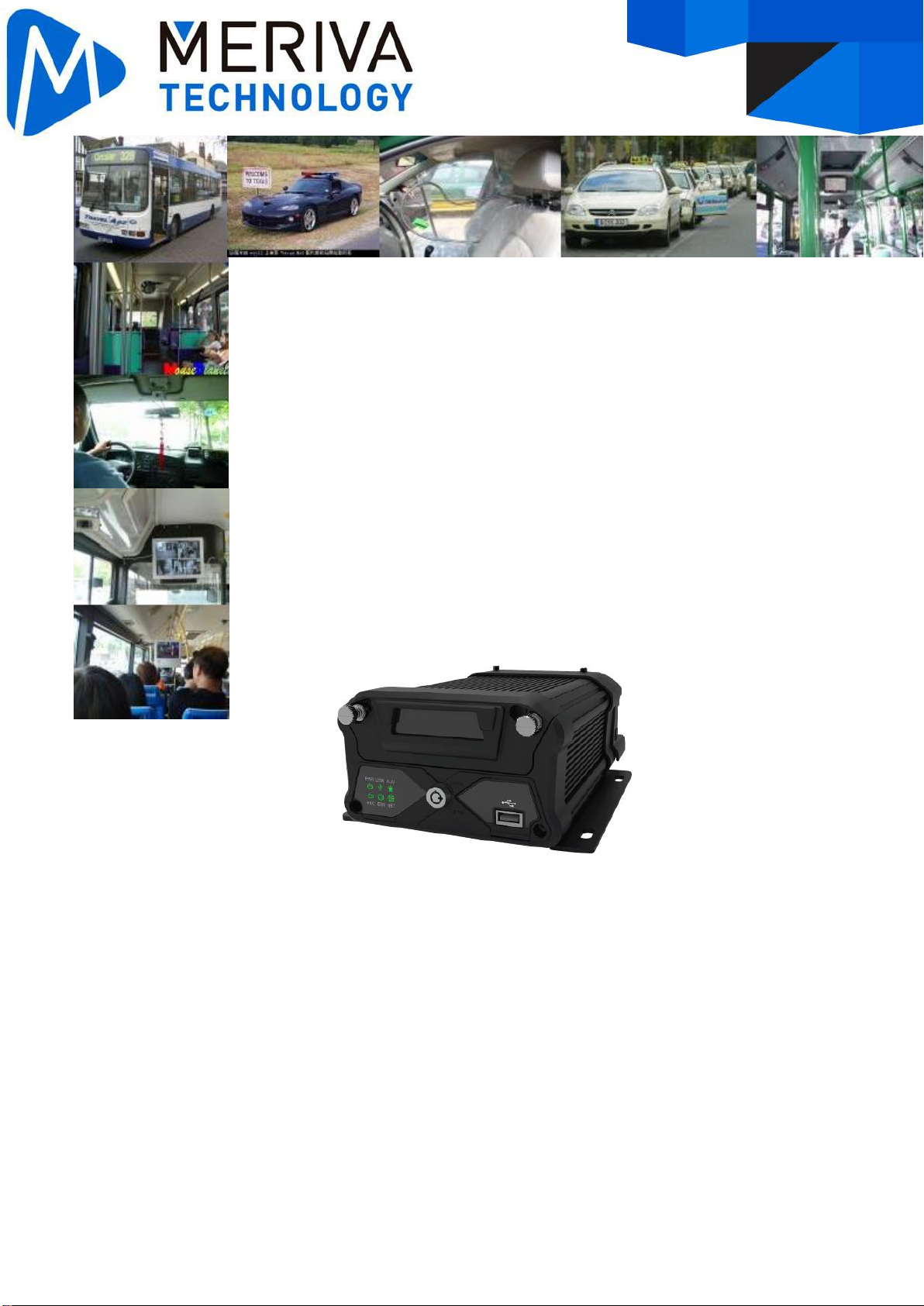
1.1. Overview
MX3 is a functional Mobile Digital Video Recorder specially designed for vehicle video surveillance
and remote monitoring. It has a high-speed processor and embedded operating system, combining with
the most advanced H.265 video compression / decompression technology, 3G/4G network, GPS
positioning technology, as well as WIFI. It supports not only videorecording in108OP, 720P, WD1, WHD1,
WCIF, D1, HD1 and CIF formats, but also vehicle travel information recording and wireless data upload.
With center software it also achieves alarm linkage central monitoring, remote management and playback
analysis. It is easy to use with simple design, multi-functions, superior anti-vibration, anti-electromagnetic
interference, radiation protection, hard disk storage, SD backup, flexible installation and high reliability.
1.2. Specifications
Technical Items
Technical Indicators
Product Model
MX3
Function Overview
Preview, Recording, Playback, Network, Locating
System
Operating System
Linux 3.18.20
Control Mode
CP4, mouse, EasyCheck, network(3G/4G/WIFI)
Video
Input
6 x AHD
Output
2 CH (CP4+VGA)
Total Resource
PAL:
6*720P@15fps(AHD)+2*1080P@30fps(IPC)
or4*1080P@10fps(AHD)+2*1080P@30fps(IPC)
or4*720P@25fps(AHD)+2*1080P@30fps(IPC)
NTSC :
6*720P@15fps(AHD)+2*1080P@30fps(IPC)
or4*1080P@12fps(AHD)+2*1080P@30fps(IPC)
or4*720P@30fps(AHD)+2*1080P@30fps(IPC)
Video Signal Standard
(Needs external switch)
Electrical level: 1Vpp Impedance: 75Ω NTSC/PAL
Optional
Audio
Input
6 CH (6 x AHD)
Output
1 CH
Audio Signal Standard
Electrical level: 2Vpp Input impedance: 4.7kΩ
Display
Display Split
1/4/9 Image display
OSD
GPS, Alarm, Vehicle plate, Speed, Time, etc.
Operation Interface
Semi-transparent GUI

Recording
Video/Audio
Compression
Vide
o
H.264/H.265
Audi
o
ADPCM, G.711A G.711U
Image Resolution
PAL:
1080P(1920X1080), 720P(1280X720), WD1(928X576),
WHD1(928X288), WCIF(464X288), D1(704X576),
HD1(704x288), CIF(352x288)
NTSC:
1080P(1920X1080), 720P(1280X720),WD1(928X480),
WHD1(928X240), WCIF(464X240), D1(704x480),
HD1(704x240),CIF(352x240);
Digital:
1080P(1920X1080), 720P(1280X720)
Image Quality
8 Levels adjustable (Level 1 is the best)
Recording Mode
Boots up/schedule/alarm event recording
Pre-recording
0-60min
Post-recording
0-30min
Playback
Playback Channel
1/4 channel by local playback, supports WEB 1/4/8
channel by local playback
Search Mode
Date/time, channel, event
Network
3G/4G
Optional
EVDO/TD-SCDMA/WCDMA/TDD-LTE/FDD-LTE
WIFI
802.11b/g/n
Ethernet
RJ45 x 1(10/100M)
Locating
GPS
Location tracking, speed detection and time sync
Sensor
G-Sensor
Built-in 6-axis inertial sensor
Storage
HDD/SSD
1 x2.5"SATA HDD or SSD,
thickness 7mm/9.5mm/15mm, supports hard disk
heating
SD
Support SDXC 32GB/64GB/128GB/256GB, plug and
play
Interface
USB
1 x USB2.0(Type A)+ 1 x USB2.0(Type B)
SD
1 x SD slot
SIM
1 x SIM slot
Serial
2 x RS232, 1 x RS485
CAN
1 x CAN
I/O
8 inputs, 2 outputs
Speed
1 channel pulse speed detection
Control Panel
CP4
Intercommunication
1 MIC port(CP4)
Power
Input
DC 8~36V
Output
5V@500mA & 12V@500mA
Max Power
Consumption
6.75W (not include cameras, screen and HDD)
Standby Power
Consumption
≈0W
Physical
characteristics
Dimension(mm)
252x167.2x88.7 (with bracket and rear shield)
Weight(KG)
2.2KG (not include HDD)
Environment
Operating Temperature
-40℃ ~+70℃ (with heating and no HDD)
-40℃~ +55℃ (with heating and HDD)
Operating Humidity
8%-95%(No condensation)
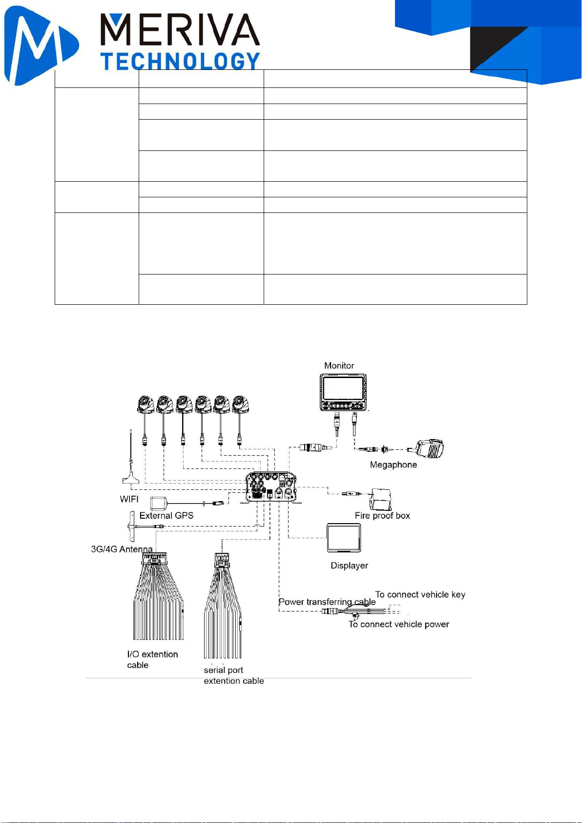
1.3. System diagram

1.4. External interface
Dimension (Unit: mm)
Front panel

Rear panel
Serial No.
Print
Description
1
A/V IN1~6
Analog audio/video input 1~6
2
VGA
VGA video interface
3
WAN
100Mbps network interface
4
USB
USB 2.0 interface (Type B)
5
3G/4G antenna interface
6
GPS antenna interface
7
WIFI antenna interface
8
Sensor&Serial
Sensor & serial interface
9
Serial
Serial interface
10
Panel
Control panel interface(CP4)
11
Power
DC8-36V power input
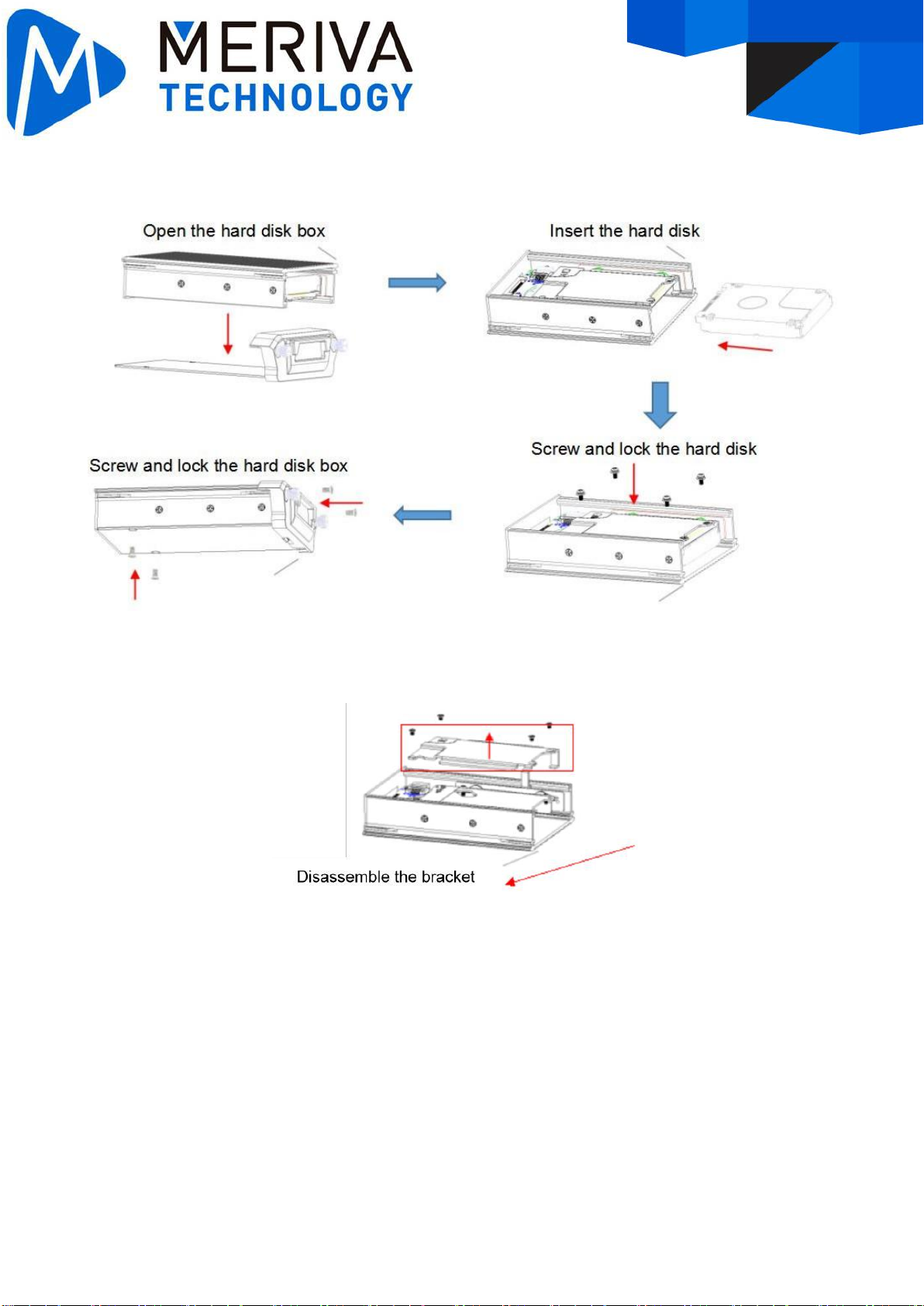
1.5. Hard disk installation
The procedure to install the hard disk of 9.5mm/7.5mm
The procedure to install the hard disk of 15mm
To install the hard disk of 15mm, user needs to disassemble the brackets, and then insert it.
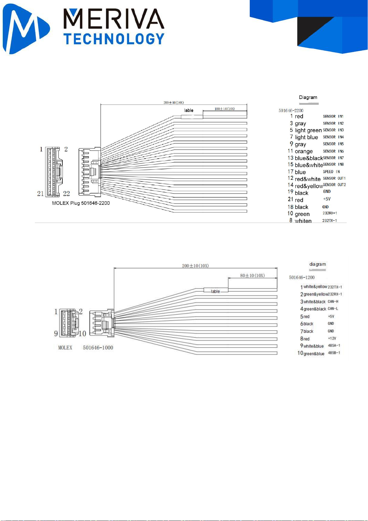
1.6. Definition and pictures of external cables
Alarm cable definition
Serial port definition

2.
FAQ
1)
The system can’t start?
Usually this problem results from the incorrect power connection. Please follow below steps to
check the power connection:
1.
Check the input power, whether the power wire is connected correctly, whether the ground wire is
connected back to the battery, and whether the fuse on the power wire is in goodcondition.
2.
Check whether the ACC signal wire input to the power is with voltage higher than 7 V.
3.
Check whether the device key is closed.
2)
The MDVR restarts uninterruptedly?
Please follow below steps to check it:
1.
Check whether the voltage of MDVR is insufficient. If the voltage is less than the start-up voltage of
the device, the device would always restart.
2.
The problem in hard disk/SD card may cause the failure to start. Take off the storage part and check
whether it is broken down.
3)
The device can’t record?
Usually this problem results from the storage disk or camera. Please follow below steps to check it:
1.
Check whether the storage disk is installed, whether it is in good contact, and whether the disk can
be read normally in computer.
2.
Check whether the storage disk is formatted. The storage disk should be formatted before normally
storing record files.
3.
Check whether there is video signal input into the device from camera, and whether there is
video/image on the screen.
4)
There is no voice in record file?
Please follow below steps to check it:
1.
Check whether there is an external pickup, or whether the camera features with the function of
audio collection.
2.
Access to Video Channel Settings, check if Audio is set on.
3.
There must be video input into the channel for recording and it must record normally.
5)
The GPS works abnormally?
Please follow below steps to check it:
1.
Check whether the GPS antenna is installed correctly. There is a silk print logo on the GPS antenna
holder behind the host device.
2.
Check whether the antenna receiver is sheltered. It should not be covered by any stuff, which may
cause it not to receive signals.
3.
Environmental influence such as tree shades, being inside tunnel, driving near tall building or elevated
roads, thunderstorms or other weather influence, etc. can also cause signal loss or receiving wrong
signals.
6)
The device can’t shutdown in ignition switch mode?
1.
Check if the ACC line connection mode is correct; and check whether there is voltage on ACC yellow
line when the key is turned off.
2.
If the device has been set with schedule recording, it can’t shutdown if it is still during recording time
of the task table.
Table of contents
Popular DVR manuals by other brands


CiA
CiA DIGITAL VIDEORECORDER WITH LAN MANAGEMENT 4 CH / 9 CH / 16 CH... user manual

Samsung
Samsung STB-E7500 user manual

Fast Forward Video
Fast Forward Video mini dvr pro user manual

Digital ID View
Digital ID View IV-MX4POENVR user manual

Saten
Saten ST-DVR16HFI72 user manual

Domar
Domar HYBRID user manual


