Merlin M2000PE User manual
05/04
1
Toll free helpline
Please have your serial number and
model name available before calling.
Australia 1800 638 234
New Zealand 0800 653 667
United Kingdom 0800 073 0112
www.merlingo.com
Installation instructions
remote control openers
security at your fingertips
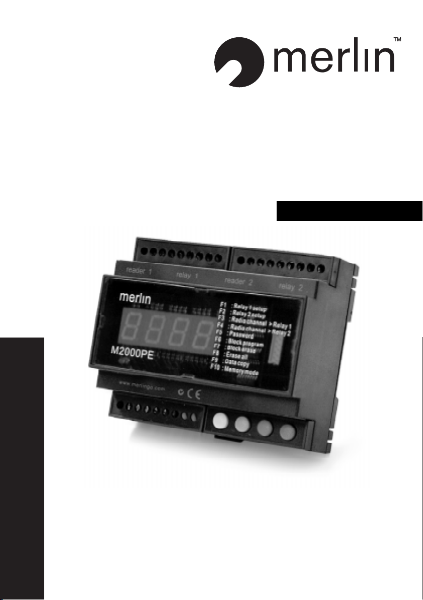
M2000PE
access controller for two doors

05/04
2
Important safety instructions
These warnings are an integral and essential part of the product, and must be delivered to
the user. Read them carefully; they provide important installation, operating, and mainte-
nance instructions. Keep this form and give it to any persons who may use the system in the
future. Incorrect installation or improper use of the product may cause serious danger.
Installation instructions
Installation must be performed by a qualified professional and must observe all local, state,
national and European regulations.
Before starting installation, make sure that the product is in perfect condition.
Laying, electrical connections, and adjustments must be done to “Industry Standards”.
Packing materials (cardboard, plastic, polystyrene, etc.) are potentially dangerous. They must
be disposed of properly and kept out of the reach of children
Do not install the product in an explosive environment or in an area disturbed by electro-
magnetic fields.
The presence of gas or inflammable fumes is a serious safety hazard.
Provide an over-voltage protection, mains/knife switch and/or differential on the power
network that is suitable for the product and conforming to current standards.
The manufacturer declines any and all liability if any incompatible devices and/or compo-
nents are installed that compromise the integrity, safety, and operation of the product.
Only original spares must be used for repair or replacement of parts.
The installer must supply all information regarding the operation, maintenance, and use of
individual components and of the system as a whole.
Maintenance
To guarantee the efficiency of the product, it is essential that qualified professionals per-
form maintenance at the times and intervals required by the installer, by the manufacturer,
and by current law.
All installation, maintenance, repair and cleaning operations must be documented. The user
must store all such documentation and make it available to competent personnel.
Warning for users
Carefully read the enclosed instructions and documentation.
This product must be used for its intended purpose only. Any other use is improper and
therefore dangerous. The information contained herein and in the enclosed documentation
may be changed without notice, and are in fact provided in an approximate manner for
application of the product. Merlin declines any and all liability in this regard.

05/04
3
Introduction
The M2000PE is an access controller for the operation of two doors.
It has an integrated Merlin high security code hopping radio receiver. It also has two Wiegand
inputs for external readers, and two 9 V dc outputs to power them.
Two output relays, each with a 5-amp capacity, allow direct connection to electric locks.
An enabling link on the relays further allows either output to be controlled by one or two
simultaneous inputs, for selected management of either person plus vehicle or personnel
only.
An anti-pass back option allows for exit control management,
A 4-digit LCD display is used for programming and assigning readers or transmitters to a
total memory capacity of 2000 users. The LCD momentarily displays the assigned code
on each valid access.
Connection to the serial port of a PC running WIN-GT/SYSTEM software is possible
using the INT485C adapter. This allows the remote entering or deletion of either individual
or blocks of serial numbers. Alternatively, the handheld GT/SYSTEM terminal can be used.
Four buttons, with colour ID and the aid of the LCD display, offer easy to use setup, pro-
gramming, and parameter setting.
All settings can be password protected.
The M2000PE is housed in a plastic enclosure suitable for indoor installations and for
DIN rail mounting.
Radio interference
Radio interference can reduce the performance of radio frequency (RF) remote controls.
RF remote controls are required to operate in shared radio frequency bands. Regulations
permit other users to continuously operate higher powered devices such as baby monitors
or wireless headphones in these shared bands. These devices may cause radio interfer-
ence that reduces the performance of your remote control. Switch off interfering devices
if possible.
05/04
4
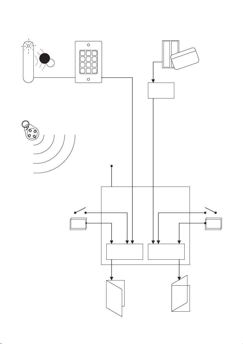
M2000PE
Port 1
Rolling code
+ serial #
+ button #
Validate rol ling code (RF only)
Validate seri al no (2000 ma x)
Detect passback (if req)
Detect enabling loop
Determine user group (if req)
Activate relay (1-180 sec)
Any prox reader
generatin g
26 or 30-bit
Wiegand data
Or any ISO2 or
37-bit Wiegan d
card reader
MW30
converter
ISO2 or 37-bit Wiegand
30-bit Wiegand
Port 2
Door 2Door 1
NO Enable
loop 2
Manual
control 2
Manual
control 1
NC
Enable
loop 1 NONC
Or any keypad
generatin g
26 or 30-bit
Wiegand data
1 2 3
4 5 6
7 8 9
* 0 #
Any Merlin wireless remote control:
handheld, keyring, wall switch or keypad
05/04
5
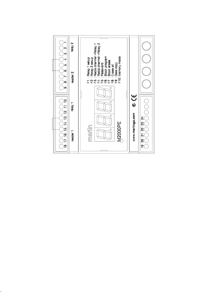
Connections
Note Make sure that terminals 4 & 6 and 13 & 15 are bridged if no enabling loop is used.
Whatever bridges these terminals must be Normally Closed in order for each relay to oper-
ate.
When connecting a Merlin aerial to the antenna terminal, cut off the MCX connector and
expose 20 mm of braid. Twist this and connect to the ‘antenna shield’ terminal. Connect the
centre core to the ‘antenna’ terminal. Take care to avoid short circuits from stray strands of
shield wire.
Over-riding pushbuttons or keyswitches connected to terminals 5 & 6 and 14 & 15 must be
Normally Open.
The maximum cable distance to readers is 100 metres.
Relay 2
Relay 2 output NC
Relay 2 output C
Relay 2 output NO
Relay 2 enabling link
Relay 2 activation input
ground
Wiegand input - DATA1
Wiegand input - DATA0
Power to reader: 9V dc
Relay 1
Relay 1 output NC
Relay 1 output C
Relay 1 output NO
Relay 1 enabling link
Relay 1 activation input
ground
Wiegand input - DATA1
Wiegand input - DATA0
Power to reader: 9V dc
green – VAL (validate)
red – INC (increment)
blue – DEC (decrement)
yellow – FUN (function)
RJ-11 connector
to GT/SYSTEM
ground
+12-24 V dc/ac 10%
RS485:A to PC
RS485:B to PC
Antenna shield
Antenna
05/04
6
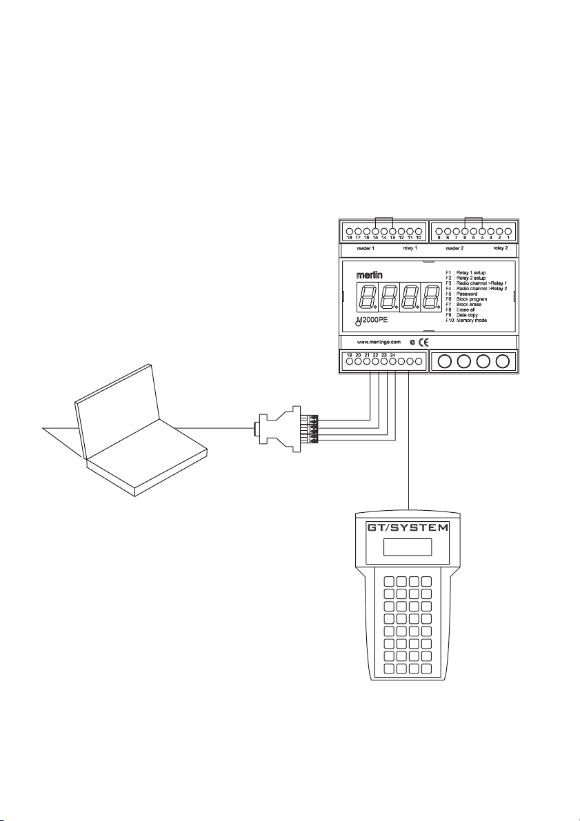
Programming connections
It is possible to perform all the necessary programming from the front panel of the M2000PE.
However, in some instances, it may be useful to programme it in other ways.
A PC running WIN-GT-SYSTEM software can be connected through an INT485C adapter.
The PC requires a serial port.
The handheld GT/SYSTEM programmer can be connected into the RJ11 port.
INT485C
GT/SYSTEM
PC running WIN-GT-SYSTEM
M2000PE
RS232
10m max RS485
1000m max
RJ11
1000m max

05/04
7
Setup
Note: VAL, DEC, INC, and FUN refer to the green, red, blue and yellow buttons on the
M2000PE.
Channels 1 to 4 correspond to the buttons of the Merlin wireless devices as follows:
Assigning codes to memory
Memory locations range from 0001 – 2000. Any combination of wireless devices, proxim-
ity tags, card readers, or Wiegand keypads can be assigned to these locations. This can be
done by accessing programming mode, selecting which memory space is to be used, and
then assigning the device.
a) Simultaneously press INC & DEC to enter programming mode.
b) Select a free location by scrolling with INC & DEC from 0001 to 2000. A free
location is indicated by decimal points being off.
c) Press wireless device button once (any button), or have the badge read by
reader. The decimal points will switch on e.g. 0.0.0.1.
d) Press VAL to confirm. The decimal points will briefly flash when the assignment
is complete.
e) Repeat steps b) to d) to assign more devices, or simultaneously press INC &
DEC to exit programming mode.
Note that codes can alternatively be assigned in blocks using the F6 function described
later.
Deleting codes from memory
Deleting an assignment from an individual location is described below. Bulk and block
erase options are described later.
a) Simultaneously press INC & DEC to enter programming mode.
b) Scroll using INC & DEC to display the location whose code is to be deleted.
Decimal points will be on, e.g. 1.0.2.3.
c) Press VAL to confirm. The letter C will appear on the left of the display.
d) Press VAL again to confirm deletion. The assigned code will be deleted and the
decimal points will go off, e.g. 1 0 2 3
e) Repeat steps b) to d) to delete more devices, or simultaneously press INC &
DEC to exit programming mode.
ch 2
ch 1
ch 3
H128C
ch 3
ch 2
ch 1
ch 4
M840
ch 2
ch 1
H128C
ch 2
H128C
ch 1
ch 2
M842
ch 1
ch 2
ch 4ch 3
M844

05/04
8
F1, F2: relay 1 setup, relay 2 setup
Relays can be individually programmed to either toggle or operate for a period of 1 –180
seconds
a) Simultaneously press INC & DEC to enter programming mode.
b) Press FUN to access the function selection menu.
c) Scroll using INC & DEC to display F1 or F2 (relay 1 or relay 2).
d) Press VAL to confirm. The current parameter value will be displayed, e.g. 0002
e) Select the value to be assigned with the scroll keys. If 0000 is set then the relay
states will toggle (bistable operation). If a value of between 0001 & 0180 is set,
then the relay will be energised for that many seconds (monostable operation)
f) Press VAL to confirm. Display will return to function selection.
g) Repeat steps c) to f) for the other relay, or simultaneously press INC & DEC to
exit programming mode.
F3, F4: Radio channel > Relay 1, 2
Functions F3 & F4 assign relays 1 and/or 2 to wireless device button 1, 2, 3, or 4. For
example if you assign F3 & F4 to button 1, both outputs will operate simultaneously from
that button.
The default setting assigns button 1 to operate relay 1 (F3) and button 2 to operate relay 2
(F4).
a) Simultaneously press INC & DEC to enter programming mode.
b) Press FUN to access the function selection menu.
c) Scroll using INC & DEC to display either F3 or F4 (relay 1 or relay 2).
d) Press VAL to confirm. The current parameter value will be displayed e.g. _CH1
e) Scroll to select the desired radio transmitter channel, i.e. _CH1, _CH2, _CH3,
_CH4
f) Press VAL to confirm. Display will return to function selection.
g) Repeat steps c) to f) for the other relay, or simultaneously press INC & DEC to
exit programming mode.
F5: Password
Password protection can be set if required. If used, the password will be requested on every
access to the programming mode. The password is set by pressing any 6-key combination
of the 4 coloured keys. This results in 4096 possible passwords.
It is strongly recommended to write down the combination prior to setting. If a password is
forgotten or lost then the M2000PE must be returned to the supplier. Note that all memory
will be cleared and so all card and wireless device assignments will require re-entering.
To enter a password:
a) Simultaneously press INC & DEC to enter programming mode.
b) Press FUN to access the function selection menu.

05/04
9
c) Scroll using INC & DEC to display F5.
d) Press VAL to confirm. The letter P will appear on the left of the display.
e) Using the 4 coloured keys, enter a total of 6 presses of any combination. E.g.
Enter: yellow, blue, red, green, yellow, and blue. (Be sure you write down the
sequence first.) The letter P will flash each time a digit is entered.
f) A correctly coded sequence will return the display to F5. Note that the se-
quence must be completed within 10 seconds.
g) Simultaneously press INC & DEC to exit programming mode.
A password can only be deleted if it is known.
To delete a password
a) Simultaneously press INC & DEC to enter programming mode. The password
will be requested.
b) Key in password.
c) Press FUN to access the function selection menu.
d) Scroll using INC & DEC to display F5.
e) Press VAL to confirm. The letter P will appear on the left of the display.
f) Wait approximately 10 seconds. Once the display returns to F5 the password
has been deleted.
g) Simultaneously press INC & DEC to exit programming mode.
F6: Block program
Block entry of codes can be performed with sequential prox tags or cards.
Note that Merlin high security code hopping wireless devices can not be entered in this
manner, due to the additional security of the code hopping validation that each device
requires.
The required lower and upper free locations are selected. The lowest serial number card or
tag is assigned to the lower free location and the remaining locations are automatically
filled with the remaining serial numbers.
a) Simultaneously press INC & DEC to enter programming mode.
b) Press FUN to access the function selection menu.
c) Scroll using INC & DEC to display F6.
d) Press VAL to confirm. The lowest unassigned location will appear on the dis-
play. (Default is 0.001) Note the left decimal point is on, indicating that this
location is the lower bound of the range.
e) If required, scroll using INC & DEC to alter the lowest location to be used, e.g.
0.020
f) Press VAL to confirm. The highest unassigned location will appear on the dis-
play. (Default is 0001.) Note the right decimal point is on, indicating that this
location is the upper bound of the range.
g) Scroll using INC & DEC to display the highest unassigned location, e.g. 0029.

05/04
10
h) Press VAL to confirm. The lower bound will now be displayed again, e.g. 0.020
i) Pass the lowest serial number card or tag through the reader once, e.g. serial
no. 12350. All decimal points will display if the first code is successfully as-
signed, e.g. 0.0.2.0.
j) Press VAL to confirm. Display will return to the function selection menu.
k) Simultaneously press INC & DEC to exit programming mode.
All remaining cards or tags should now be automatically sequentially assigned to locations.
F7: Block erase
To erase a block of codes from memory.
a) Simultaneously press INC & DEC to enter programming mode.
b) Press FUN to access the function selection menu.
c) Scroll using INC & DEC to display F7.
d) Press VAL to confirm. The lowest required location for deletion will appear on
the display. (Default is 0.001) Note the left decimal point is on, indicating that
this location is the lower bound of the range.
e) If required, scroll using INC & DEC to alter the lowest location to be deleted, e.g.
0.020
f) Press VAL to confirm. The highest location for deletion will appear on the dis-
play. (Default is 0001.) Note the right decimal point is on, indicating that this
location is the upper bound of the range.
g) Scroll using INC & DEC to display the highest location for deletion, e.g. 0029.
h) Press VAL to confirm. The letter C will be displayed.
i) Press VAL again to confirm the block erase. Codes in all locations from the
lower to the upper selection will be deleted. Display will return to the function
selection menu.
j) Simultaneously press INC & DEC to exit programming mode.
F8: Erase all
Codes can be erased from all locations. However this will not affect other stored param-
eters such as relay times or channel assignments.
a) Simultaneously press INC & DEC to enter programming mode.
b) Press FUN to access the function selection menu.
c) Scroll using INC & DEC to display F8.
d) Press VAL to confirm. The letter C will be displayed.
e) Press VAL again to confirm the bulk erase. Codes in all locations will be deleted.
Display will return to the function selection menu.
f) Simultaneously press INC & DEC to exit programming mode.
F9: Data copy
Codes may be transferred serially in blocks from locations in one M2000PE to the same

05/04
11
locations in another M2000PE, or to a PC running the WIN-GT/SYSTEM programme. It is
possible to add or delete serial numbers using the PC and transfer these to the M2000PE,
instead of directly entering each device using a reader or through the receiver.
Connect the M2000PE to another M2000PE using the RJ-11 plug. Connect to a PC
using screw terminals 21 and 22 (see page 5) and INT485C.
a) Simultaneously press INC & DEC to enter programming mode.
b) Press FUN to access the function selection menu.
c) Scroll using INC & DEC to display F9.
d) Press VAL to confirm. The lowest required location for transfer will appear on
the display. (Default is 0.001) Note the left decimal point is on, indicating that
this location is the lower bound of the range.
e) If required, scroll using INC & DEC to alter the lowest location to be transferred,
e.g. 0.020
f) Press VAL to confirm. The highest required location will appear on the display.
(Default is 0001.) Note the right decimal point is on, indicating that this location
is the upper bound of the range.
g) Scroll using INC & DEC to display the highest location for transfer, e.g. 0029.
h) Press VAL to confirm. The display will show _ _ _ _
i) Press VAL again to confirm the transfer. The display will flash _ _ _ _ while the
codes in all locations from the lower to the upper selections are being trans-
ferred. Display will return to the function selection menu.
j) Simultaneously press INC & DEC to exit programming mode.
Note that pressing FUN will revert the unit back to the function selection menu unless data
transfer has commenced.
Note: Data will only show on the PC once it has been copied from the M2000PE module.
Data entered into the PC will only show on the M2000PE module once it has been copied
to the module.
This is achieved from the ‘memory’ menu, ‘copy’ option, ‘file to module’, or ‘module to file.’
F10: Memory mode
Three different relay assignment options for wireless devices are available on the M2000PE
unit: F, H, & P. Note that using H or P option will result in all code stored in all locations to be
deleted.
F This is the default mode, where relays are activated according to their assign-
ment in F3 and F4. Namely:.
All locations activate relay 1 from a particular wireless channel, set up using F3
All locations activate relay 2 from a particular wireless channel, set up using F4
This function is useful to allow all users to operate each relay from the same
channels on their remotes.
One channel can operate both relays, or different channels can operate each
relay.

05/04
12
H This mode is to allow some restriction on user access to some doors. Namely:
Locations 0001 to 1000 activate relay 1 only; select which radio channel using
F3
Locations 1001 to 2000 activate relay 2 only; select which radio channel using
F4
If one wireless device is to operate two relays, then it must be assigned to two
locations, for example:
Location 0001, channel 1 (button 1), relay 1
Location 1001, channel 2 (button 2), relay 2
And so a user who is allowed to access only one relay should only be stored in
only one location.
P This anti-pass back function is useful to prevent multiple entries without exiting
using the same card.
Card must be assigned to relay 1 and to relay 2.
Relays must be activated in sequence by the same card.
To select F, H, or P options:
a) Simultaneously press INC & DEC to enter programming mode.
b) Press FUN to access the function selection menu.
c) Scroll using INC & DEC to display F10.
d) Press VAL to confirm. The display will show the current mode selected, e.g. F
e) Scroll using INC & DEC to display F, H, or P
f) Press VAL to confirm. The display will return to the function selection menu.
g) Simultaneously press INC & DEC to exit programming mode.

05/04
13
Warranty
Receiver/controller Limited Warranty
Merlin warrants to the original purchaser (“the Buyer”) that the Merlin receiver/controller
(“the Unit”) sold under this warranty will be free from defects in materials and workmanship
for a period of 24 months from date of purchase.
Accordingly if the Unit fails due to defects in materials or workmanship within the warranty
period Merlin will, provided the defective part or Unit is returned freight and insurance
prepaid and well packaged to the nearest address listed in this manual, undertake to repair
or, at its option replace, any defective part or Unit and return it to the Buyer at no cost.
Repairs and replacement parts are warranted for the remaining portion of the original
warranty period.
Limitations
It expressly excludes any batteries and malfunctions or defects to the Unit or its operation
due to any of the following:
A Failure to observe installation, adjustment, maintenance or operating instructions pro-
vided with the Unit;
B Incorrect installation, operation or adjustment of any device to which the Unit is fitted;
C Connection to any device outside the specifications set out in the owners manual;
D Any modification or repair to the Unit carried by a person not authorised to do so by
Merlin;
E Radio or any other electrical or electronic interference;
F Faulty or unsuitable electrical wiring of the building to which the Unit is attached;
G Faulty or flat batteries in the remote control transmitter;
H Where the defect is due to: conditions other than normal domestic use or dirt, misuse,
neglect, fire, accident, electrical storm or other act of God.
This warranty is void if the serial number has been altered, defaced or moved. The liability of
the Distributor for any loss or damage or injury arising directly or indirectly from any defect
in the goods supplied is limited to the replacement or repair of such goods or to damages
not exceeding the invoice value of such goods at the option of Merlin.
Future Modifications
Merlin may modify any existing or future model of the Unit without the obligation to incor-
porate these modifications into Units already manufactured or into the Unit to which this
warranty applies.
General
This warranty is the only Warranty made by Merlin. All other warranties, representations
and conditions of any kind, express or implied, are hereby excluded. Nothing in this war-
ranty is intended to have the effect of contracting out of the provisions of the Consumer
Guarantees Act (1993) except to the extent provided by that Act and all provisions of this
warranty shall be read and modified to the extent necessary to give effect to that intention.
This warranty does not deprive the Buyer of any rights conferred upon them by any appli-

05/04
14
cable law or statute in their country of purchase.
Proof of date of purchase may be required when making a claim under warranty. In the
event that the Buyer is unable to provide adequate proof of purchase the date of warranty
will apply from date of shipment from the Distributor to the Reseller.
NOTE We request that you attach your sales docket or invoice to this manual to enable
you to establish the date of purchase in the unlikely event of a service call being made.
In-warranty service During the warranty period, if the product appears as though it may
be defective, call our toll free service before removal of the unit. A Merlin technician will
diagnose the problem, or provide you with shipping instructions for a factory repair or
replacement. If an Authorised Installer installed your unit you must call them for prompt on-
site service.
After warranty Need help after the warranty period? Need help obtaining parts, service
and accessories? See your yellow pages or phone Merlin toll free.
Specifications
Receiver type Super heterodyne, SAW filtered,
433.92 MHz, FM – FSK
Compliance C-tick and CE
Input voltage 12–24 V ac /dc +/- 10%
Power consumption 100 mA
IP rating IP33, for indoor use only
Dimensions 105 x 90 x 60h
Weight 350 grams
Input types Merlin high security code hopping wireless
device, 4 channels:
2 x Wiegand data, 26 or 30 bit (no settings
required); 37 bit using optional MW30 con-
verter
2 x PB (wired push button, Normally Open)
No of output channels 2
Output type relay contacts, timed from 1-180 sec, or
toggling
Output assignment each relay assignable to any wireless chan-
nel or card reader; restricted assignment for
some users
Max switching load 5A at 30 V dc
Number of users 2000 in any combination of wireless or wired
devices
Password protection 6-key sequence of four buttons
Power out to reader 9v dc

05/04
15
Accessories
MW30 Converter for either mag stripe (ISO2) or 37-
bit Wiegand readers to connect to the 26 or
30-bit Wiegand input on the M2000PE.
GT/SYSTEM Handheld programmer for connection to
M2000PE, or M200R or M1000R memory
modules.
WINGTSYSTEM Software for a PC to be connected to the
M2000PE.
INT485C Converter from RS485 to RS232. Used to
connect a PC with a serial port to the
M2000PE.
M001 Externally mountable aerial with ground plane
for potential RF performance improvement.
Has 2 m of cable and an MCX connector.
M002 10 metre extension cable for M001, with
MCX connector fitted.
Input devices
Proximity reader Any reader with Wiegand 26 or 30-bit data
output.
Any reader with Wiegand 37-bit output (re-
quires MW30 converter)
Combination device Merlin M842IT (two button keyring remote
control with internal proximity tag)
Merlin M842IT (four button keyring remote
control with internal proximity tag)
Mag-stripe reader Any Wiegand 26 or 30-bit output reader.
Any ISO2 output reader (req. MW30 con-
verter)
Wired keypad Any keypad with Wiegand 26 or 30-bit data
output.
Any keypad with Wiegand 37-bit data output
(requires MW30 converter)
Keyring remote control Merlin M842I (two button)
Merlin M844I (four button)
Wireless keypad Merlin M840 (wall mount, weather resistant)
Wireless wall-switch Merlin H128A (one button)
Merlin H128B (two button)
Merlin H128C (three button)

05/04
16
Merlin service centres
New Zealand
Auckland phone 09 415 4393
Phone toll free 0800 653 667 or 0800 MERLIN
Fax toll free 0800 653 663
Australia
NSW, Vic, Qld, WA
Phone toll free 1800 638 234
Fax toll free 1800 888 121
Europe
United Kingdom
Phone toll free 0800 073 0112
Fax +44 1709 514 534
SE Asia
Malaysia
Phone 03 3323 6026
Fax 03 3323 7026
www.merlingo.com
Table of contents
Other Merlin Remote Control manuals


