manuals.online logo
Brands
  1. Home
  2. •
  3. Brands
  4. •
  5. MERLYN
  6. •
  7. Plumbing Product
  8. •
  9. MERLYN 6 Series User manual

MERLYN 6 Series User manual

Thank you for choosing Merlyn.Please familiarise yourself
with the fitting instructions before commencing fitting.
1. Check that you have the tools required.
2 that the installation site is compatible . Check
with size of door supplied
3. Check all the enclosure components.
4 that the installation kit is complete. Check
DO NOT attempt to install the product unless you can
tick ALL 4 boxes as satisfactory.
The wall plugs supplied with the installation kit are for
use in solid walls. Hollow or 'stud-partition’ walls will
require alternative fixings. Please consult a hardware
supplier for the correct type.
It may also be necessary to consult your tiling supplier
about the correct method for drilling your tiles.
VIVID
10
IMPORTANT
Any parts missing or damaged must be reported to your supplier within 5 days of purchase.
Inspect shower enclosure before fitting. No claims will be acceptable after product has been installed.
USE SAFETY EYEWEAR WHEN DRILLING
SLIDING DOOR
INSTALLATION GUIDE
SHOWER WALL
M042-00
COMPONENTS AND BOX CONTENTS 1
Support bar ferule
Horizontal support bar holder
Small
fixing wall
1
Screw cover cap
Bottom
water
seal
Cover cap for wall profile
∅6 30 wall plugX
Screw cover cap clip
Wall
profile
Top
cover
cap L/R
6
5
2
9
8
7
10
11
12
13
14
15
1
3
DescriptionNo. QTY Description QTY
Part No. No. Part No.
1
1
3
6
3
1
1
2
1
1
B
head
screw ST4 30X
Note:Further part details for fixing kit available on page 2
3
4
B head screw ST4 12X
6
Small
fixing wall
2
V6
V4111
Flat
fixed
panel
Bottom fixed bracket
Rail
to wall
16
A
6
7
4
3
2
5
8
9
1
1 0 1 1
1 3
1 5
1 4
1 8
1 9
1 7
1 6
1 2
2 0
ST5 50 countersunk screwX
countersunk screwST4 40 X
17
18
19
20
ST5X50 countersunk screw
wall plug∅X7 36
V6MLN05
V6LP8076L/R
V6113
V2114
V2115
V4110
V6BM31950
V6H081100
V8123
V4115
V6S6SW05
V6ST4 40X
V8119
V1121
V4115
V8121
V8122
V8125
2
1
1
1
2
1
1
4
2 1
2 2
2 3
21
22
23
Rail
to ceiling
Vertical cover sleeve
Vertical ceiling mount
1
1
1
V1120
V6S6SW07A
V8118
Rail ferule
Wall mount
6
7
4
3
2
5
8
9
1
1 0 1 1
1 3
1 5
1 4
1 8
1 9
1 7
1 6
1 2
2 0
2 1
2 2
2 3
2 0
Tools Required
- 6mm and 7mm masonry drill bit
- Power drill
- Quality Silicone
- Pencil
- Tape Measure
- #2 Philips Head screw driver
- Spirit level with horizontal and vertical level indicators
IMPORTANT - Installation site
1. Ensure the top surface of the shower tray on which the enclosure will be installed is level in every direction.
2. The tiles or other wall finishing should be effectively sealed at the tray edges.
3. Tiles should extend at least to the corners of the tray and a minimum of 2.0 metres from the top of the tray.
FIXING KIT COMPONENTS, TOOLS REQUIRED, SITE 2
V8124
1X
V6113
X3
V8125
X4
V4111
X3
V2115
6X
V2114
X6
V6ST4 40
2
×
X
V4115
X4
V6M5 5
3
X
X
1
V6115
X
V6LP8076 L
X1
V6LP8076 R
X1 V6MLN05
X1
V8121
X1
V8122
X1
V8119
X1
V6S6SW05
X1
V8126
X1
V8127
X1
V8123
X1
V6S6SW07A
X1
V8118
X1
V4110
X3
V6M5 5
1
X
X
V1120
X1
V1121
X1
Horizontal rail
Vertical rail
FITTING WALL PROFILE 3
PROCEDURE
100% level
TRAY MUST BE 100% LEVEL IN ALL DIRECTIONS
Ensure the shower tray is level in all directions and is
properly sealed to the wall. The wall must be tiled down to
the top edge of the tray. Do not angle out bottom tile.
TRAY MUST BE SEALED FULLY AROUND WHERE THE
TRAY MEETS THE WALL.
V6113
Inside
∅6mm masonry bit
V6BM31950
V4111
V2114
MAX.
950mm
Step 1.
The max. distance from the inside face of the profile to the wall is 950mm. Place the wall profile in from the front edge
of the shower tray, plumb, mark & drill holes.
Step 2 .
Fix the wall profile into position with wall plugs and screws V4111
Do not silicone behind wall profile to wall, see sealing section.
V6113 .
2
FITTING DOOR PANEL 4
Step 3.
Identify the top of the panel column, by
ensuring the screw holes line up with the
panel correctly, and secure the support bar
ferrule V6S6SW05 with 2 screws V6ST4X40.
Step 4.
Position floor support ferrule V8123 on bottom of panel A and
slide it into the wall profile.
Note: Ensure glass is fitted with label showing from
outside.
Step 5.
Note: If fitting on a tiled floor ONLY, option to screw
floor. Position panel A into wall profile and mark position on
floor V8123 remove panel and fix V8123 to floor using plugs
V8125
V8123 to
and screws V4115. ANTI-SLIP PADS V8126 & V8127
ARE OPTIONAL.
Step 6.
Press the seal gasket V6H081100 onto the bottom
edge of the glass.
NOTE: This can be sealed to the floor/tray with
silicone if required or omitted and use silicone
only as required.
3
4
5
V8123
V6H081100
V6ST4 40X
V6S6SW05
6
OPTION 1-FITTING HORIZONTAL TOP RAIL 5
Step 7.
Re-position panel into wall profile and onto the ferrule on the tray,
drill through profiles at similar position to wall fixing screws and fix to
wall profiles with screws V4110,clips V2114 & snap-on caps V2115.
Step 8a.
Screw the horizontal support bar holder V8119 onto the
support bar ferrule V6S6SW05. Step 9a.
Cut the support bar
Insert the horizontal support bar V1121 into the holder V8119
and position the assembled wall ferrule V8121-V8122 at the
other end. Level the bar and mark the position, remove the
bar and ferrule assembly.
V1121 to size . DO NOT CUT TOO SHORT
Step 10a.
Align and secure the wall mount
horizontal support bar wall ferrule V8121 using
plugs sad screws V4115.
V8122 for the
Step 11a.
Screw the ferrule
the wall mount. Insert the
support bar V1121 right into the
holder V8119 then slide it back
into the wall ferrule.
V8121 onto
Step 12a.
Check panel column is plumb vertical.
Tighten the grub screws at both ends of the support bar to
secure.
TIGHTEN TIGHTEN
∅7mm
masonry bit
V8125
V6115 V2114 V4110
V2115
LEVEL
MARK
INSERT
7
8a 9a
10a
11a
12a
V8119
V8122
V4115
V8122
V8121
V6M5X5
6
Step 8b.
Measure from the top of the support bar ferrule
V6S6SW05 to the ceiling and . Cut the
vertical support bar V1120 to this length.
subtract 1cm
NOTE: Do not cut end with internal thread on
V1120.
Step 9b.
Screw the support bar V1120 to the ferrule V6S6SW05 with the ceiling mount
V6S6SW07A loose in the top. Ensure the support bar is plumb vertical and mark the
position for the mount on the ceiling. Remove the bar and fix the mount to the ceiling
using plugs and screws
.
V8125 V4115.THE CEILING MOUNT MUST BE SECURED
TO A JOIST OR OTHER SOLID COMPONENT
Step 10b.
Slide the cover sleeve over
the bar and insert the bar into the
ceiling mount V6S6SW07A. Screw
the bar down onto the support ferrule
V6S6SW05. Tighten the grub screws
in the ceiling mount.
V8118 Step 12b.
Screw the cover sleeve up onto
the ceiling mount over the secured
support bar.
V8118
V6S6SW07A
V4115
V8125
V8118
9b
12b
8b
MEASURE
OPTION 2-VERTICALFITTING TOP RAIL
V1120
10b
V8124
11b
Step 11b.
Tighten the screw V6M5
V8124.
X5 using
TIGHTEN
V6M5X5
SEALING AND TROUBLE SHOOTING 7
Step 13.
Step 14.
Use a quality silicone sealant and
applicator gun to seal the finished
door.
Seal top to bottom on the
between the wall profile and the
wall. Note: do not apply sealant on
the inside of the tray / floor.
Seal only along bottom on the
between it and the tray /
floor and approx 50mm up between
the wall profile and the wall.
Fix the top cover cap & V6MLN05
V6LP8076.
Seal at
vertical joints on bottom of
frame on outside only.
SEALING INSIDE
INSIDE
SEALING OUTSIDE
OUTSIDE
24 HRS
TROUBLE SHOOTING GUIDE
1. Is the tray / floor level where the shower wall is located? ( )
2. Is the shower wall sealed correctly to the floor and wall in the correct location ( )
3. Is the wall profile plumb? ( )
4. Top rail will not reach the back wall. Ensure that the back wall is not leaning back. (away
from the tray at the top) The distance from the
be maximum 950mm ( )
see page 3
see step 14
see step 1
see step 1
inside of the wall profile to the back wall
should
50mm
13
V6LP8076L/R
V6MLN05

Other manuals for 6 Series

7

Other MERLYN Plumbing Product manuals

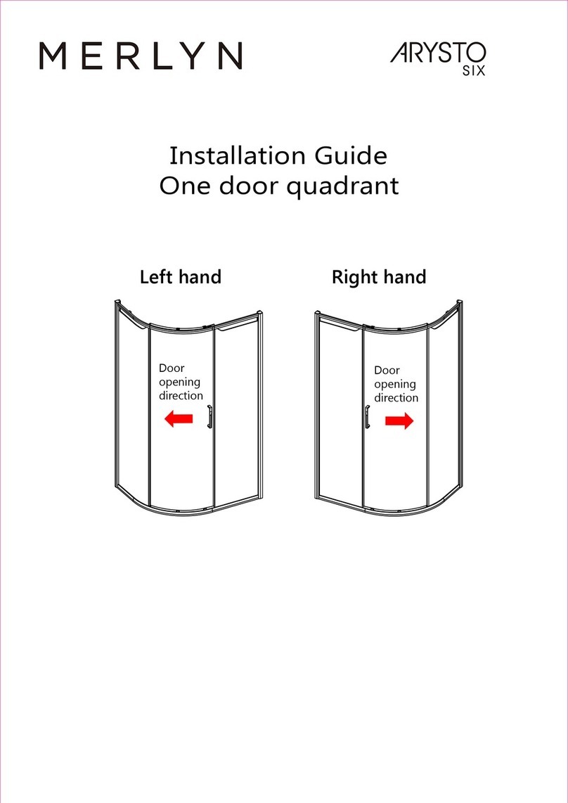
MERLYN arysto six User manual

MERLYN

MERLYN arysto six User manual

MERLYN 8 Series User manual

MERLYN

MERLYN 8 Series User manual

MERLYN ARYSTO COLOUR GHB1100 User manual

MERLYN

MERLYN ARYSTO COLOUR GHB1100 User manual

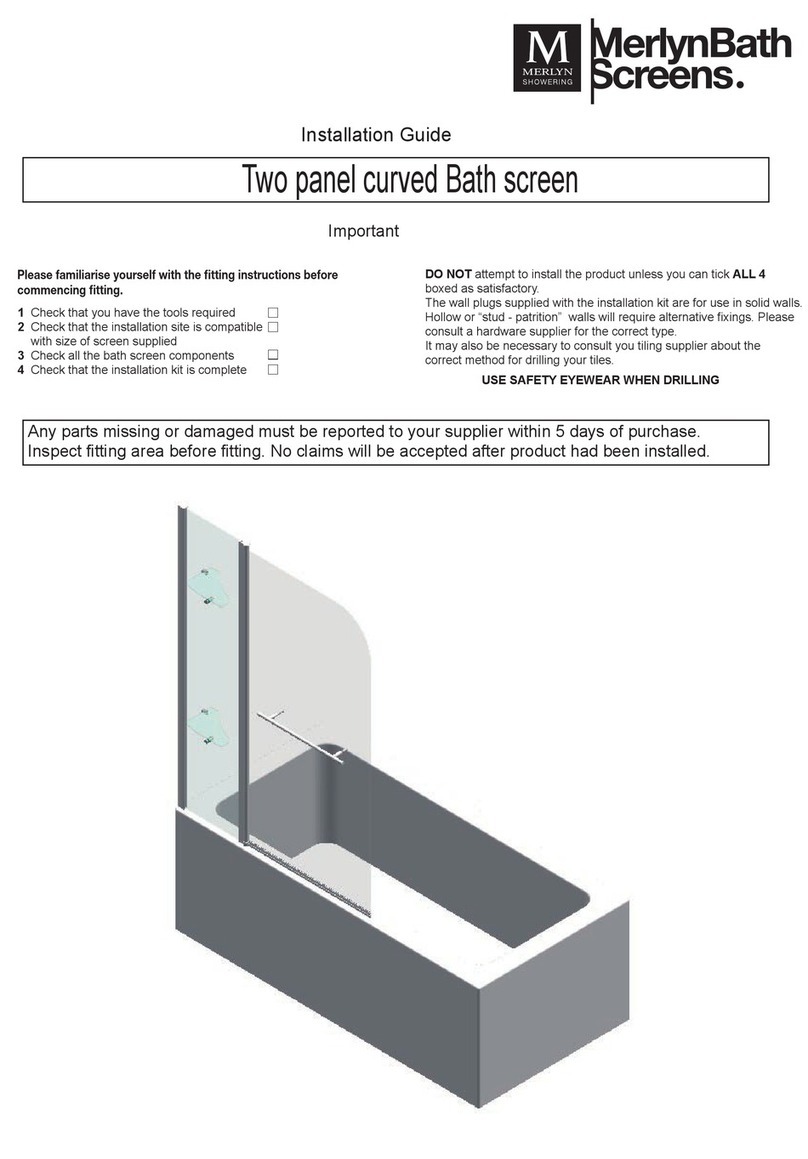
MERLYN MB3 2 Panel Curved Bath Screen User manual

MERLYN

MERLYN MB3 2 Panel Curved Bath Screen User manual

Popular Plumbing Product manuals by other brands

Hans Grohe Talis Classic 14127 Series Instructions for use/assembly instructions

Hans Grohe

Hans Grohe Talis Classic 14127 Series Instructions for use/assembly instructions

Laufen ILBAGNOALESSI One 8.1197.2 Installation

Laufen

Laufen ILBAGNOALESSI One 8.1197.2 Installation

Bristan Java J BASNW C Fitting Instructions & Contents List

Bristan

Bristan Java J BASNW C Fitting Instructions & Contents List

ABI INTERIORS 316 SS quick start guide

ABI INTERIORS

ABI INTERIORS 316 SS quick start guide

saunalife Garden Series manual

saunalife

saunalife Garden Series manual

Toto TBV01801U Installation and owner's manual

Toto

Toto TBV01801U Installation and owner's manual

Helvex Vertika E-701-S installation guide

Helvex

Helvex Vertika E-701-S installation guide

Glacier bay 67099-0A01 Installation and care guide

Glacier bay

Glacier bay 67099-0A01 Installation and care guide

Wolff Finnhaus Melina 40 Building instructions

Wolff Finnhaus

Wolff Finnhaus Melina 40 Building instructions

Graff TARGA 2309000 Instructions for assembly and use

Graff

Graff TARGA 2309000 Instructions for assembly and use

Bristan Descent DSC BAS C Installation instructions and user guide

Bristan

Bristan Descent DSC BAS C Installation instructions and user guide

Grohe Elberon 30 211 manual

Grohe

Grohe Elberon 30 211 manual

Luxart VELERO VE7SA installation instructions

Luxart

Luxart VELERO VE7SA installation instructions

Bossini EXEDRA Z003201 Installation and maintenance instructions

Bossini

Bossini EXEDRA Z003201 Installation and maintenance instructions

Aqualisa HiQu HQD1005 installation guide

Aqualisa

Aqualisa HiQu HQD1005 installation guide

Bradley S19-270HD Installation

Bradley

Bradley S19-270HD Installation

Heritage Bathrooms TDCC00 Installation instructions and user guide

Heritage Bathrooms

Heritage Bathrooms TDCC00 Installation instructions and user guide

Kohler STATEMENT K-26325T-CP installation instructions

Kohler

Kohler STATEMENT K-26325T-CP installation instructions

manuals.online logo
manuals.online logoBrands
  • About & Mission
  • Contact us
  • Privacy Policy
  • Terms and Conditions

Copyright 2025 Manuals.Online. All Rights Reserved.