Merriott LST Style 2 User guide

PANEL
LENGTH
(mm)
TOP
BRACKET
SUPPORT
BOTTOM
SUPPORT
DIST. A DIST. B FIG
NO.
G10, G15,
G17, G25
B10, B15,
B17, B25
0 0
1 1 609 0 1
1 1 909 0 1
1 1 1209 0 1
2 2 909 1809 2
PANEL
LENGTH
BOTTOM
SUPPORT
DIST. A DIST. B FIG
ST0, ST5,
ST7, ST9
2
3 609 0 1
3 909 0 1
3 1209 0 1
4 909 1809 2
Item no. Parts included Qty
1 Front Panel 1
2 Endboxes 2
3HorizontalTop Grille 1
4 Horizontal Boom Grille 1
5 Bracket Kit (Grille) 1
Information for the installer LSTStyle Wall mounted - suitable with horizontal Precision emiers
MPILH
E
150
150
150
150
103 153 176 259
E E E
EMITTER/LST CASE
POSITIONING
‘X’ Value = 150mm unless otherwise specified
to suit TRV location
INTERMEDIATE BRACKET PANEL DEPTH & BRACKET TYPE
Important Notes:
• Fixings for LSTassembly are included in
the Bracket Kit (item 5). Content will vary
depending on the length of the LST.
• Fixings to install LSTto the wall are not
included.
• Emier and fixings shown on exploded
view. Installation instructions provided with
emier.
• Boom grille (item 4) measures 20mm
LESS than the overall casing length.
FIG.
FIG.
Merrio UK & Ireland
Purmo Group (UK) Ltd,
Eastern Avenue,
Team Valley, Gateshead,
Tyne & Wear, NE11 0PG
Tel: 0330 0415 472
sales@merriouk.com
sales @merrio.ie
www.merriouk.com / www.merrio.ie
Follow us on @merriouk and
All dimensions are in mm.

Information for the installer LSTStyle Wall mounted - suitable with horizontal Precision emiers
MPILH
Installation Procedure:
1. ForTRVcutout positions and LST
locations to suit, contact the Merrio
sales office.
2. Fix endboxes to wall surface as
shown in FIG. ensuring that required
dimensions are adhered to.The centre
of the boom bracket corresponds to
the centre of the intermediate tabs
on the front panel.The boom of
the bracket should be in line with the
boom of the endboxes.
3. Slide boom grille onto endboxes and
fix using the M4 hex socket screws
and grille locking plates provided.
(If boom brackets are required, fix
immediately aer the boom grille is
fixed, see FIG. ).
4. Locate tabs on inside of front panel.
Slide into slots provided in endboxes.
Push the panel into its upright position
and lock in place using M8 nuts and
washers (see FIG. ).
5. Place top grille in position as shown
in FIG. . Lock in place by inserting
M4 hex socket screws through the
keyhole plates in the grille and into the
threaded hole in the endbox.
FIG.
FIG.
FIG.
FIG.
Emier
Height
Case
Height
143mm 350mm
215mm 420mm
288mm 490mm
360mm 560mm
433mm 630mm
505mm 700mm
578mm 770mm
650mm 840mm
723mm 910mm
795mm 980mm
THE REQUIRED CLEARANCE BETWEEN THETOP
OF THE EMITTER ANDTHETOP OFTHE ENDBOX
‘X’ DIMENSION AS ON PREVIOUS PAGE

Item no. Parts included Qty
1 Front Panel 1
2 Endboxes 2
3SolidTop 1
4 Horizontal Front Grille 1
5 Horizontal Boom Grille 1
6 Bracket Kit (Solid Top) 1
Information for the installer
MPILH
EMITTER/LST CASE
POSITIONING
‘X’ Value = 150mm unless otherwise specified
to suit TRV location
PANEL
LENGTH
(mm)
BOTTOM
SUPPORT
SOLID TOP
SUPPORT
FIXING
SUPPORT
DIST. A DIST. B FIG
NO.
B10,B15,
B17, B25
S10, S15,
S17, S25
ST0, ST5,
ST7, ST9
0-1000 0 0 2
1001-1550 1 1 4 609 0 1
1501-2150 1 1 4 909 0 1
2151-2750 1 1 4 1209 0 1
2751-3000 2 2 6 909 1809 2
Important Notes:
• Fixings for LSTassembly are included in
the Bracket Kit (item 6). Content will vary
depending on the length of the LST.
• Fixings to install LSTto the wall are not
included.
• Emier and fixings shown on exploded
view. Installation instructions provided with
emier.
• Boom grille (item 5) measures 20mm
LESS than the overall casing length.
LSTStyle Wall mounted - suitable with horizontal Precision emiers
INTERMEDIATE BRACKET PANEL DEPTH & BRACKET TYPE
FIG.
FIG.
E E E E
150
150
150
150
103 153 176 259
All dimensions are in mm.
Merrio UK & Ireland
Purmo Group (UK) Ltd,
Eastern Avenue,
Team Valley, Gateshead,
Tyne & Wear, NE11 0PG
Tel: 0330 0415 472
sales@merriouk.com
sales @merrio.ie
www.merriouk.com / www.merrio.ie
Follow us on @merriouk and

Information for the installer
MPILH
Installation Procedure:
1. ForTRVcutout positions and LST
locations to suit, contact the Merrio
sales office.
2. Fix endboxes to wall surfaces as
shown in FIG. ensuring that required
dimensions are adhered to.
3. Slide boom grille onto endboxes and
fix using the M4 hex socket screw and
grill locking plates provided. If boom
brackets are required, fix immediately
aer the grille is fixed (see FIG. ).
4. Locate tabs on inside of front panel.
Slide into slots provided in endboxes.
Push the panel into its upright position
and lock into place using M8 nuts and
washers (see FIG. ).
5. Fix solid top into position with bolts
provided.
6. Place top grille in position as shown
in FIG. . Lock into place by inserting
M4 hex socket screws through
keyhole plates in the grille and into the
threaded hole in the endbox.
FIG.
FIG.
FIG.
FIG.
Emier
Height
Case
Height
143mm 455mm
215mm 515mm
288mm 585mm
360mm 655mm
433mm 725mm
505mm 795mm
578mm 865mm
650mm 935mm
723mm 1005mm
795mm 1075mm
THE REQUIRED CLEARANCE BETWEEN THETOP
OF THE EMITTER ANDTHETOP OFTHE ENDBOX
‘X’ DIMENSION AS ON PREVIOUS PAGE
LSTStyle Wall mounted - suitable with horizontal Precision emiers
125mm

Item no. Parts included Qty
1 Front Panel 1
2 Endboxes 2
3SolidTop 1
4 Top Front Grille
(6 bar grille)
1
5 Boom Horizontal Grille 1
6 Bracket Kit (Solid Top) 1
MPILV
Information for the installer
Important Notes:
• Fixings for LSTassembly are
included in the Bracket Kit (item 6).
Fixings to secure LST to the wall are
not included.
• Boom horizontal grille (item 5)
measures 20mm LESS than the
length of the overall casing.
• Emier ED35 with LST unit shown
on exploded view. Installation
instructions are provided with
emier.
• Emier height should be at least
343mm less than the overall height
of the LST.
• For emiers with connection EF/
GH, the case width should be
emier width + 140mm.
• For emiers with connection BD/
AD, the case width should be
emier width + 280mm.
ES ED
EMITTER / LST CASE POSITIONING
ES ED
LSTStyle
Wall mounted - suitable for vertical Profile emiers
188
155 155 155 155
100
min. 100
min. 100
min.
100
min.
255 255 255 255
188 188 188
236
153
153153
All dimensions are in mm.
Merrio UK & Ireland
Purmo Group (UK) Ltd,
Eastern Avenue,
Team Valley, Gateshead,
Tyne & Wear, NE11 0PG
Tel: 0330 0415 472
sales@merriouk.com
sales @merrio.ie
www.merriouk.com / www.merrio.ie
Follow us on @merriouk and

Installation Procedure:
1. Fix endboxes to the wall 100mm
up from the floor (see FIG. ).
2. Slide boom grille on to the
endboxes and fix using M4 hex
socket screws and grille locking
plates provided (see FIG. .
3. Affix emier to wall between the
endboxes ensuring at least 155
mm between the boom of the
radiator and the boom grille.
4. Locate tabs on inside of the
front panel and line up with slots
on endbox. Push panel into its
upright position and fix using M8
nuts and washers provided.
5. Affix solid top using bolts
provided (see FIG. .
6. Install top front facing grille by
inserting Mhex socket screws
through the keyhole plates and
into a threaded hole which is
located in the endbox (see FIG. .
MPILV
Information for the installer
FIG.
FIG.
FIG.
FIG.
LSTStyle
Wall mounted - suitable for vertical Profile emiers
Min. 100mm
Min. 100mm
Min. 100mm
Min. 100mm
Table of contents
Popular Industrial Equipment manuals by other brands

Blacoh
Blacoh SENTRY CIP Installation and operation manual
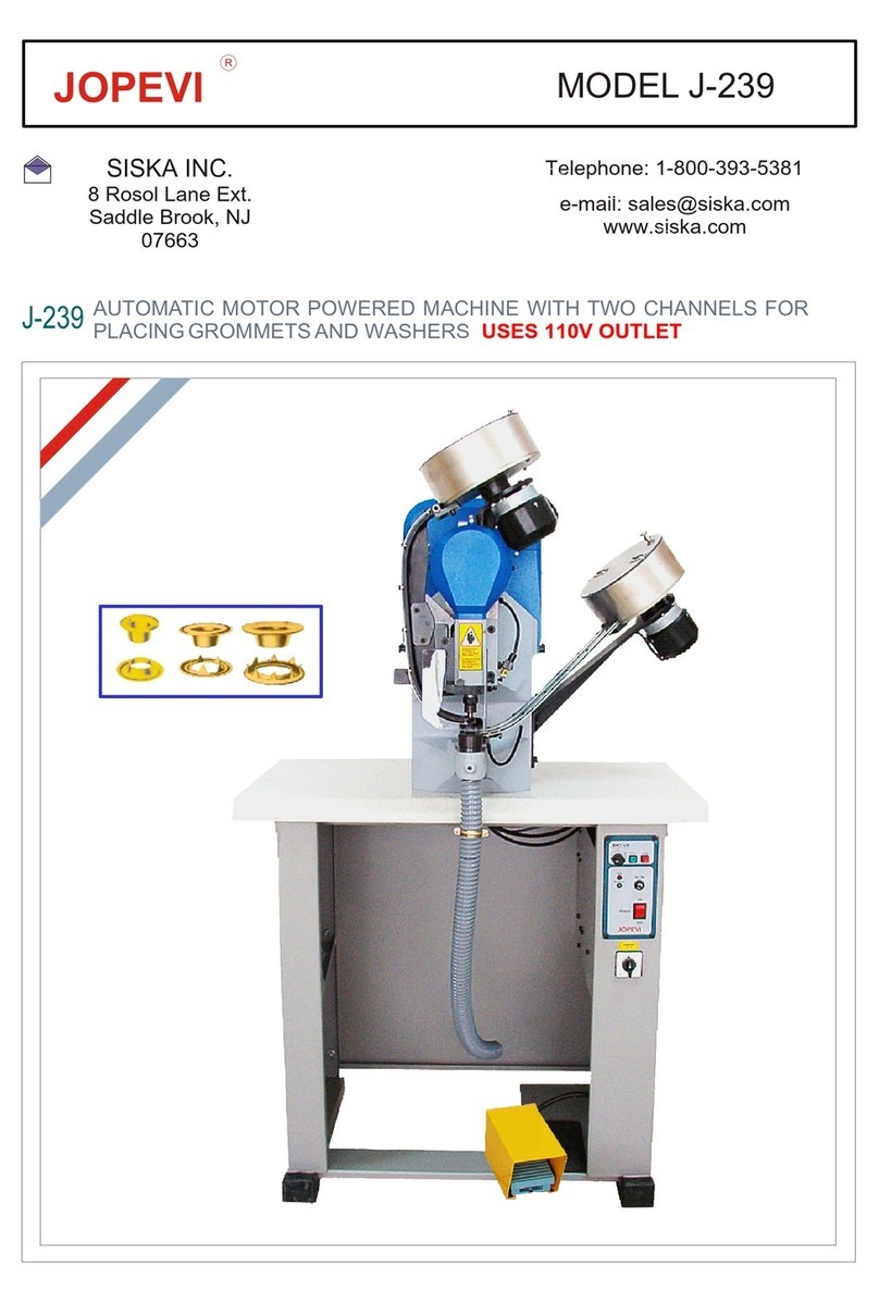
JOPEVI
JOPEVI J-239 manual
Lega
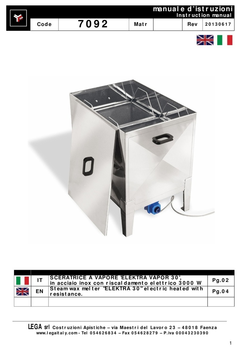
Lega 7092 instruction manual
Honeywell
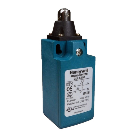
Honeywell MICRO SWITCH GLL Series Insallation Instructions
LUCOMA
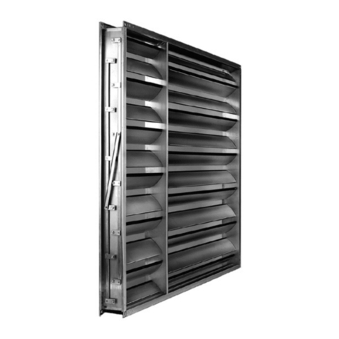
LUCOMA RGK-10 Series Installation, operation and maintenance instructions
Spirotech
Spirotech SpiroVent Superior S6A user manual
