7
ATE FB15 Operating Manual
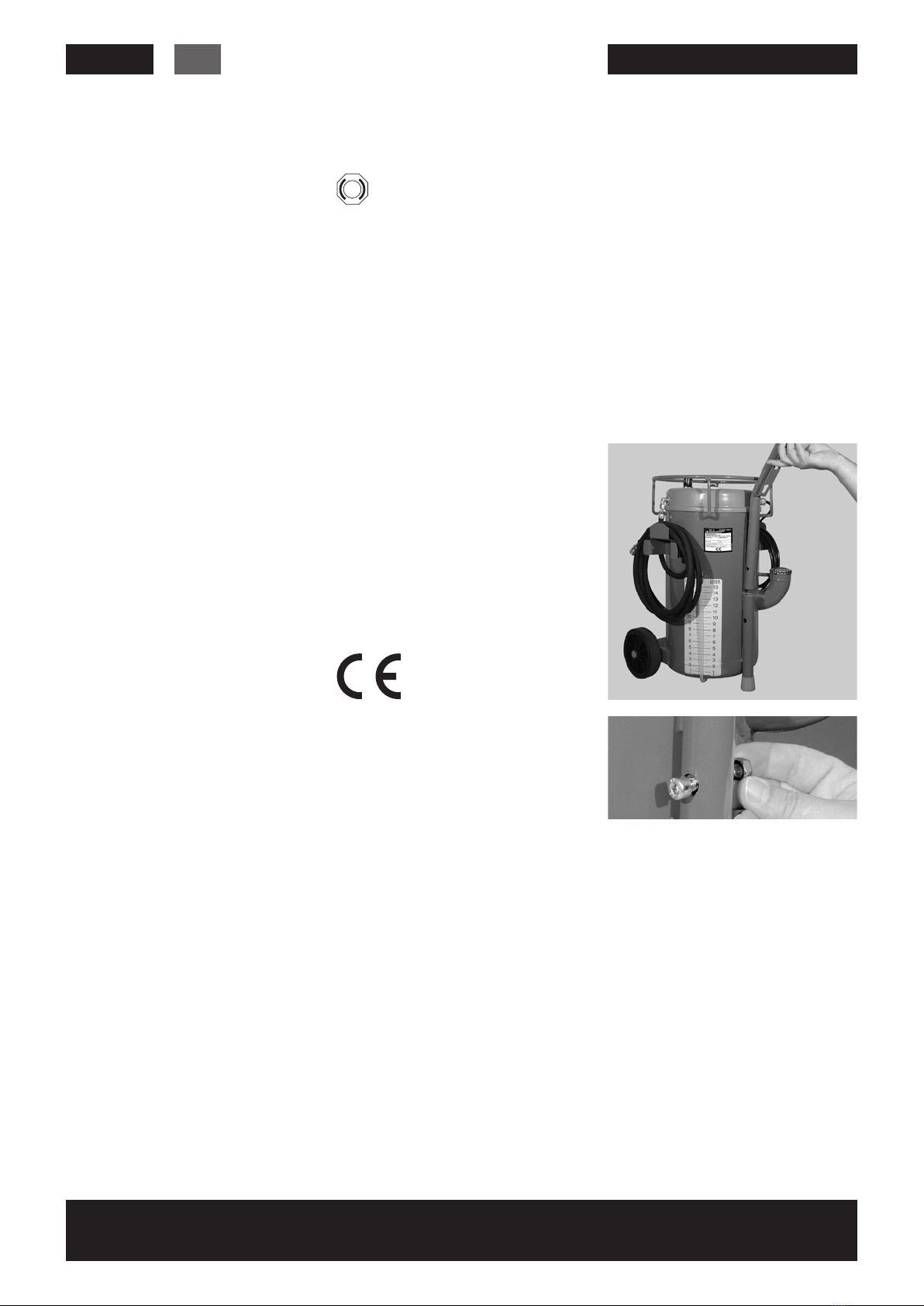
Commissioning
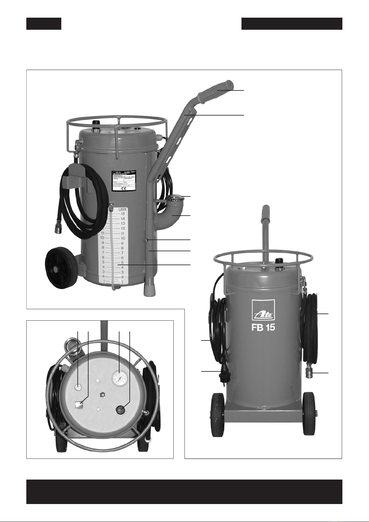
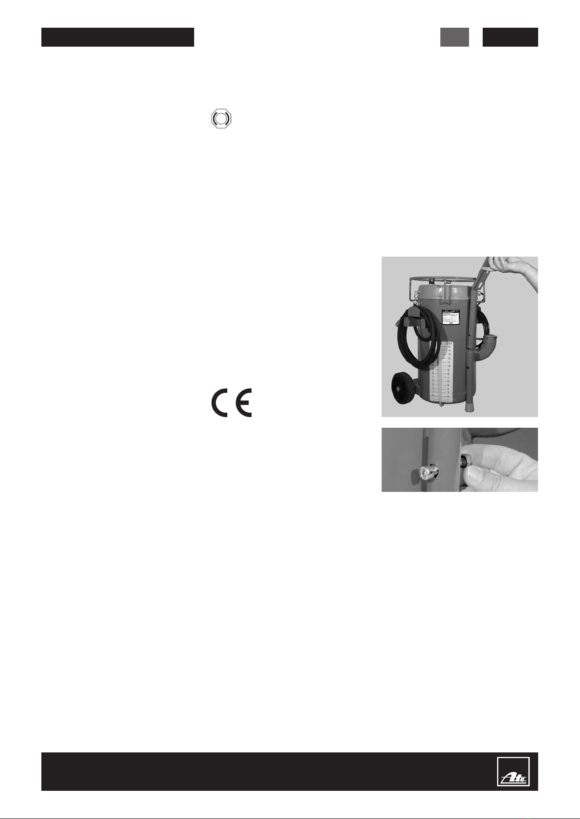
1. Remove the fluid filling cap (14), fill
with fluid – maximum filling capacity
15 liters–; seal the filling tube (15) again
2. The filling level is shown on the fluid-
level indicator
3. Connect the mains connector (05) to
a correctly earthed socket
4. To bleed the unit, connect ATE filling
gun (B) or ATE bleeding unit adapter
(C) to the filling hose (07/08); the
extracted fluid can be returned to the
unit via the filling tube (15).
5. Switch the unit on using the on/off
switch (01), allow it to run for 10 sec.,
and then switch the unit off
6. Disconnect ATE filling gun (B) or ATE
bleeding unit adapter (C)
7. The unit is ready for operation
Setting working pressure
The working pressure should be
checked every time the unit is
used.
To check the working pressure set,
remove the ATE filling gun (B) or the
ATE bleeding unit adapter (C).
With the unit switched on, read off the
working pressure at the working-pressure
manometer (03).
On delivery, the unit is set to a working
pressure of 2 bar (200,000 Pa). This
is the standard bleeding pressure for
hydraulic brake systems.
Only change the working pressure set-
ting when the unit is switched off.
Bleeding with lower or higher working
pressure: Pull the pressure regulator
button (04) to release it.
Screw in (⟳) =
increase working pressure
Screw out (⟲) =
reduce working pressure
Switch the unit on and check the work-
ing pressure. If necessary, switch the
unit on again and re-adjust the pressure.
After correct setting of the working pres-
sure, press the pressure regulator button
(04) back in to secure it.
Refilling brake fluid
If there is less than approx. 0.5 liters of
brake fluid in the unit, the pump motor
automatically switches off to prevent air
being pumped into the brake system.
At the same time, a buzzing noise is
sounded which signalizes switch-off and
an empty unit.
• Switch the unit off
• Remove the brake fluid filling cap (14)
• Replenish with new brake fluid
• Seal the filling tube (15) again
• The unit does not require bleeding
before operation
Bleeding instructions
With ABS vehicles always follow
the special bleeding guidelines
provided by the vehicle manu-
facturer.
With ABS vehicles, always carry
out controlled braking several
times on a blocked road and
repeat the bleeding procedure
if necessary.
• Before bleeding, check the brake circuit
layout; bleed each circuit completely
• Always carry out bleeding at all the
bleed valves available. Some braking
units can have several bleed valves.
• After bleeding, tighten the bleed valves
according to requirements (torque);
replace rubber dust cap
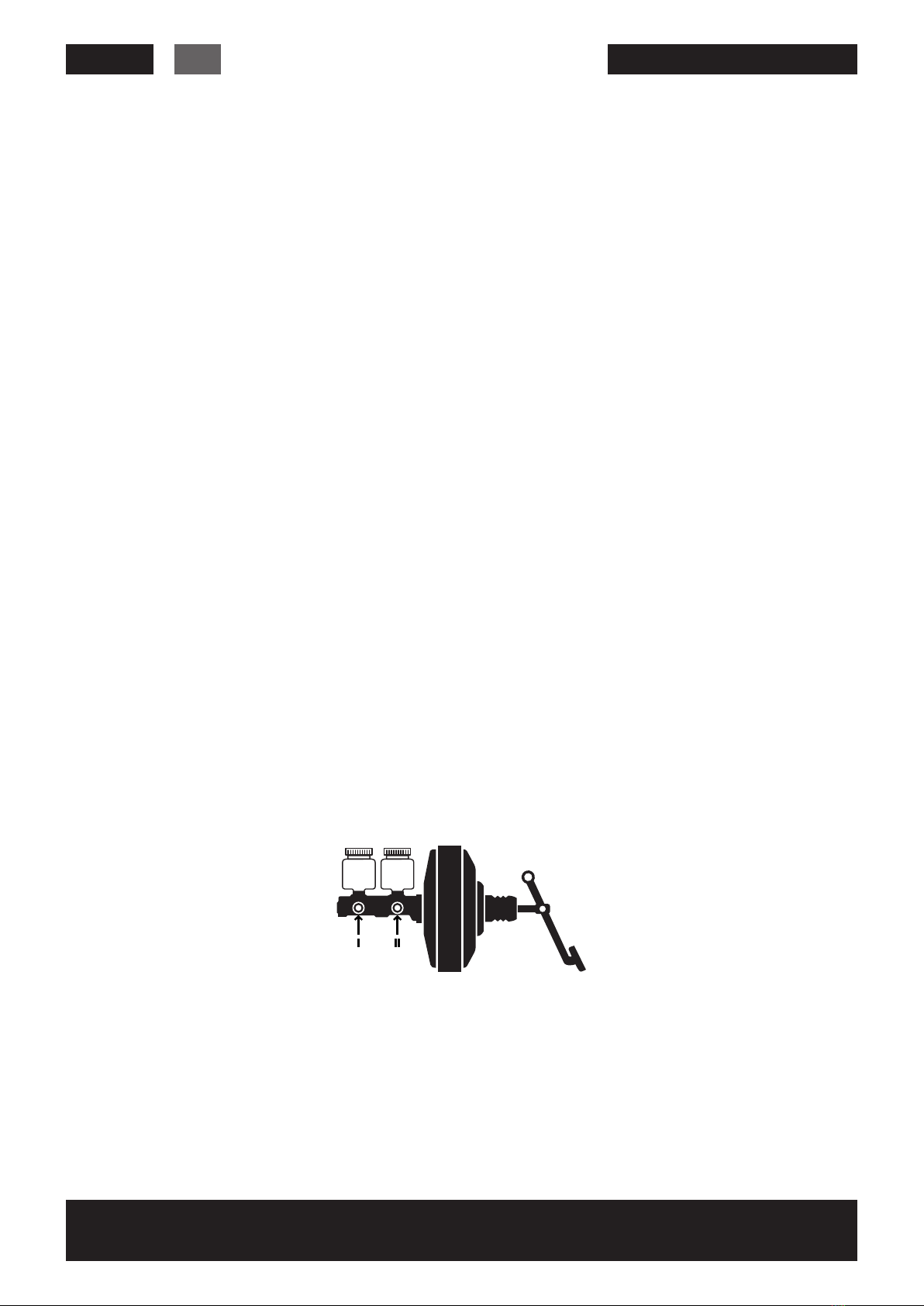
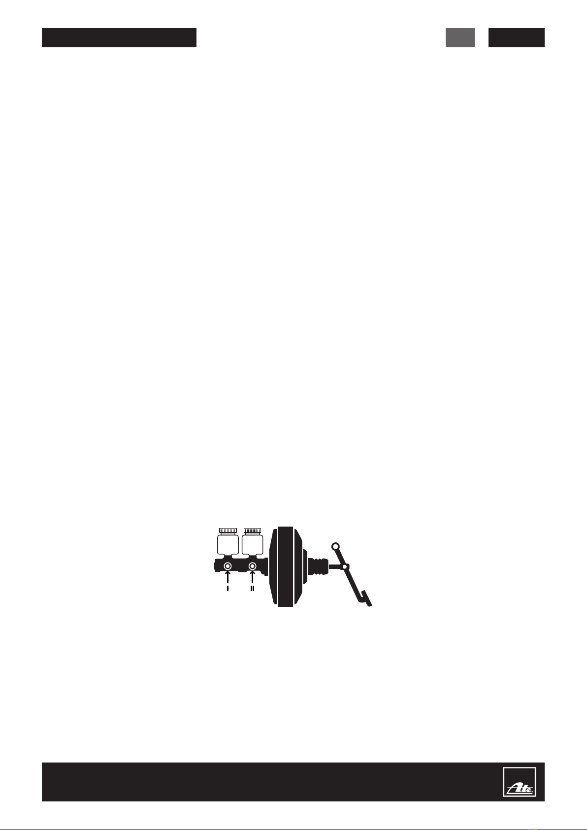
• In the case of dual-circuit brakes with
separate fluid reservoirs on each of the
brake circuits, bleed the two circuits in
succession; first the intermediate piston
(I) then the primary piston circuit (II)
• In the case of brake systems with load-
dependent brake power regulators,
the hydraulic passage to the regulated
brakes can be blocked on unburdened
axles (vehicle on 2-pillar lifting platform).
In this case, burden the wheels of the
regulated axles or actuate the regulator
in full-load position.
• If brake pedal travel is too long or
pressure build-up too “soft” after
bleeding has been carried out, bleed
again after pressing the brake pedal
forcefully several times.
• After every filling, bleeding, and brake
fluid replacement process, carry out
leakage, function and efficiency tests
on the service brake system.
Filling, bleeding the brake
system, replacing brake fluid
1. Remove the fluid reservoir cap
2. Extract the brake fluid completely
from the fluid reservoir using the ATE
suction bottle (A)
3. Connect the ATE filling gun (B) to the
filling hose (07/08); switch the unit on
4. Completely fill the brake fluid reser-
voir with new fluid; disconnect the
ATE filling gun (B)
5. Fit the suitable ATE bleeding unit ad-
apter (C) airtight to the fluid reservoir
6. Connect the filling hose (07/08) to the
ATE bleeding unit adapter (C)
7. Insert the hose of the ATE collection
bottle (D) onto a bleed valve; open
the bleed valve until fresh, clear,
bubble-free brake fluid flows out
8. Repeat the procedure on each of the
bleed valves with the collection bottle
fitted
9. When fitting a new tandem main
cylinder: Press the brake pedal down
as far as it will go several times while
the brake fluid is flowing out in order
to remove the air bubbles completely
from the tandem main cylinder
10. End of bleeding; switch the unit
off; remove the filling hose (07/08)
first, then the ATE bleeding unit
adapter (C)
11. Correct the brake fluid to the MAX
mark using the ATE suction bottle (A)
12. Check the bleeding hole of
the original fluid reservoir cap
for permeability and then fit it
GB