Merritt GOOSENECK LIVESTOCK TRAILER User manual
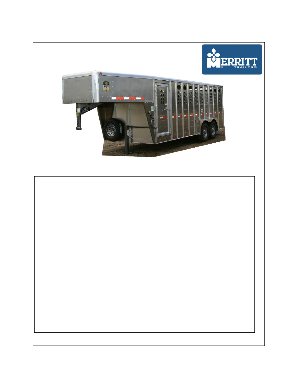
GOOSENECK LIVESTOCK TRAILER
OWNER’S MANUAL
SEE WARRANTY REGISTRATION FORM ON LAST PAGE
1-800-634-3036 . 9339 BRIGHTON RD. HENDERSON, COLORADO 80640-8229
REV A 6/16/16
79-79-0502
FORWARD
Congratulations and thank you for your purchase of a Merritt Trailers Inc. Gooseneck
Livestock Trailer . Built with pride, American engineering and manufacturing know-
how. It is designed to provide performance for years to come.
This manual is furnished to ensure that the owner\operator is aware of safe operating
procedures. It includes information about the general care and maintenance of your
Gooseneck Livestock Trailer . Also included is an operator’s manual located in a tube
holder on the lower front of the trailer.
Carefully read the following pages. If you have any questions regarding thisGooseneck
Livestock Trailer contact a Merritt dealer.
Merritt dealers have the knowledge and the
facilities to provide you with the best service possible.
We also advise you to strictly follow the recommended maintenance schedule outlined.
This maintenance schedule is designed to ensure that all critical components on this
trailer are thoroughly inspected at various intervals.
All information in this manual is based upon the latest product data and specifications
available at the time of printing. Merritt Trailers Inc. reserves the right to make
product changes and improvements which may affect illustrations or explanations.
This information is also available on our web page. (http://merritt-trailers.com/)
1-1

TABLE OF CONTENTS
WHEEL and TIRES
Wheels..................................................8-1
Torque Requirements............................8-1
Tire safety ............................................8-2
FORWARD
Introduction. .........................................1-1
GENERAL INFORMATION
Normal trailer Operation ......................2-1
Loading and unloading if livestock . . . 2-
1
Modification of Trailer.........................2-1
LOAD LIMITS
LOAD LIMITS.....................................9-1
SAFETY
Over the road safety handling...............3-1
Wheel torque ........................................3-2
SAFETY
Safety..................................................10-1
Safety..................................................10-2
BEFORE TRIP INSPECTION
Safety Chains........................................4-1
Coupler Attachment..............................4-1
Brake and Electrical controls................4-2
Brake Controls......................................4-2
Side Structure. ......................................4-2
Gates.....................................................4-3
Tires......................................................4-3
Wheel & Rims......................................4-3
Door Locks...........................................4-3
ELECTRICAL SYSTEM
Basic Wiring Diagram........................11-1
Breakaway Battery Charger ............... 11-2
12 Volt Sealed Lead-Acid Battery . . . 11-
3
Electrical Connector Wiring Diagram..... 11-3
TROUBLESHOOTING
Electrical Troubleshooting. ................12-1
Electrical Braking Troubleshooting. . 12-2
OPERATION INSTRUCTIONS
Operation of Brakes..............................5-1
Operation of Coupler............................5-1
Operation of Gates................................5-2
CONSUMER INFORMATION
Reporting Safety Defects.................... 13-1
Warranty Certificate. ..........................13-2
Warranty Schedule............................. 13-3
Warranty Certificate. ..........................13-4
GENERAL MAINTENANCE
Fasteners. . . . . . . . . . . . . . . . . . . . . . .
6-1
Floor .....................................................6-1
Gate and Ramp Hinges.........................6-1
Wheel Bearings ....................................6-1
Grease Seals..........................................6-2
General Maintenance............................ 6-2
BRAKES
Brakes...................................................7-1
Brake Adjustment.................................7-2

GENERAL INFORMATION
NORMAL TRAILER OPERATION
This Merritt Gooseneck trailer is designed for
operation within legal highway speed limits on
reasonable road surfaces for the type of service it
was built to perform, and in accordance with the
noted weight restrictions.
Normal use means the loading, unloading and
transportation of uniformly distributed legal loads,
in a manner which does not subject trailer to
stresses or impacts greater than imposed by
reasonable use.
This trailer was built to carry cargo within the two weight ratings on the identification plate
located on the road side of the trailer near the front.
The GAWR (Gross Axle Weight Rating) is the structural capability of the lowest rated
member of the running gear component suspension and spring system, hub, wheels and
drums, rims, bearings, brakes, axle, and tires.
The GVWR (Gross Vehicle Weight Rating) is the structural capability of the trailer when
supported by the kingpin and axles with the load uniformly distributed throughout the cargo.
The maximum load indicated on the identification plate may not be legal o
n the highway you
plan to use. States have differing laws and regulations, affecting vehicle lengths and weights
on the roads that are not a part of the primary interstate.
LOADINGANDTRANSPORTOFLIVESTOCK
The loading of the trailer is important! KEEPTHE CENTER OF GRAVITYAS LOWAS
POSSIBLE. Proper placement of the larger animals should be considered.
Because load types vary, drive with appropriate care and within the limits of the load.
The wellbeing of the Gooseneck Livestock Trailer is dependent on the stock density,
ventilation, skill of driving, and quality of roads. Frequent inspection of livestock and
careful driving cannot be over-emphasized!
MODIFICATION OF TRAILER
Any modifica
tion made to the trailer must comply with DOT and NHTSA regulations and
must not compromise the gross vehicle weight rating (GVWR) of the trailer.
Any operations of the trailer outside the limitations stated in this manual will void any
responsibility of Merritt Trailers Inc. for any of its results
2-1

SAFETY
OVER-THE-ROAD SAFE HANDLING
YOU AND YOURSAFETY
1. You - the operator - have control of the most important factors that affect vehicle stability.
Trailers are important tools in our transportation industry and, like any tool, are safe in the
hands of a properly qualified operator.
2. The fifth wheel coupler should be securely mounted to the tractor frame.
3. The driver should be familiar with the characteristics of the particular trailer and load being
transported.
4. The driver should be familiar with the nature of the roads and traffic encountered during the trip.
5. Stability:
Within the relatively narrow confines of road law, limiting vehicle size and weight, together
with characteristics of available tires, suspensions, and other components, there is little that a
manufacturer can do to affect the inherent stability of a trailer other than keeping the loading
decks as low as feasible, considering the requirements for loading space and adequate tire
clearance. This means that the major factor affecting operational stability are the knowledge
and skill of the driver. The predominant causes of the rollover accidents are:
Excessive speed.
Violent swerving or turning
Application of brakes or tractor power while turning
Entering curves at too high of a speed may be caused by one of the following factors:
a. Traveling at freeway speeds for long periods of time and failing to reduce it before
entering freeway interchanges or other curves requiring a reduced and controlled speed.
b. Lack of familiarity with the vehicle characteristics to recognize its safe speed
with relation to posted speed limits on curves, which are usually determined with
automobile traffic in mind.
c. Failure to reduce speed sufficiently when approaching congested traffic such as
might be found at traffic signals on highways. With the advent of today’s more
powerful and higher torque engines, the original practice of maintaining momentum
to avoid acceleration in traffic is outmoded.
3-1

SAFETY
OVER-THE-ROAD SAFE HANDLING
6.
Tire Characteristics: high pressure truck/trailer tires have different characteristics under high
speed cornering conditions than do passenger car tires. As an extreme example, it is fairly
common knowledge that a skilled race car driver can consistently “drift” his racer around
tight turns where very high lateral ”g” forces are encountered. However, truck/trailer tires
which are designed for carrying high loads over long distances have substantially different
characteristics, and their lateral stability becomes unpredictable when lateral forces approach
0.4g. This means that commercial vehicles must be operated in a conservative manner
when cornering.
Braking and Acceleration: either braking or accelerating while cornering can significantly
7.
reduce the stability of the vehicle and should be avoided. The best driving practice is to
decelerate to safe conservative speed before entering a corner or approaching congested
traffic, and then to apply only moderate power until a straight path has been reestablished.
Like any other vehicles, trailers can tip or slide out of control if turns are negotiated at too
high of a speed or when making violent maneuvers such as abrupt lane changes or other
evasive actions to avoid obstacles.
WHEELTORQUES
Proper torqueing and re-torqueing the wheel nuts are critical to prevent a premature loss of
wheel equipment.
Wheel nuts must be checked and re-torqued after 50 to 100 miles of use. This is
important every time you change a wheel.
3-2

BEFORE TRIP INSPECTIONPROCEDURE
Be careful when making inspections, hookups,
and repairs to avoid personal injury. Make
sure parking brakes are
properly active or that wheel chocks are in place to avoid sudden
or unexpected movement of the trailer which could result in bodilyinjury.
It is the Operator’s responsibility to conduct a safe and accurate pre-trip inspection of the
vehicle including brake condition and proper adjustment and be satisfied that the vehicle is in
safe operating condition. See 49 CFR Parts 383 and 396
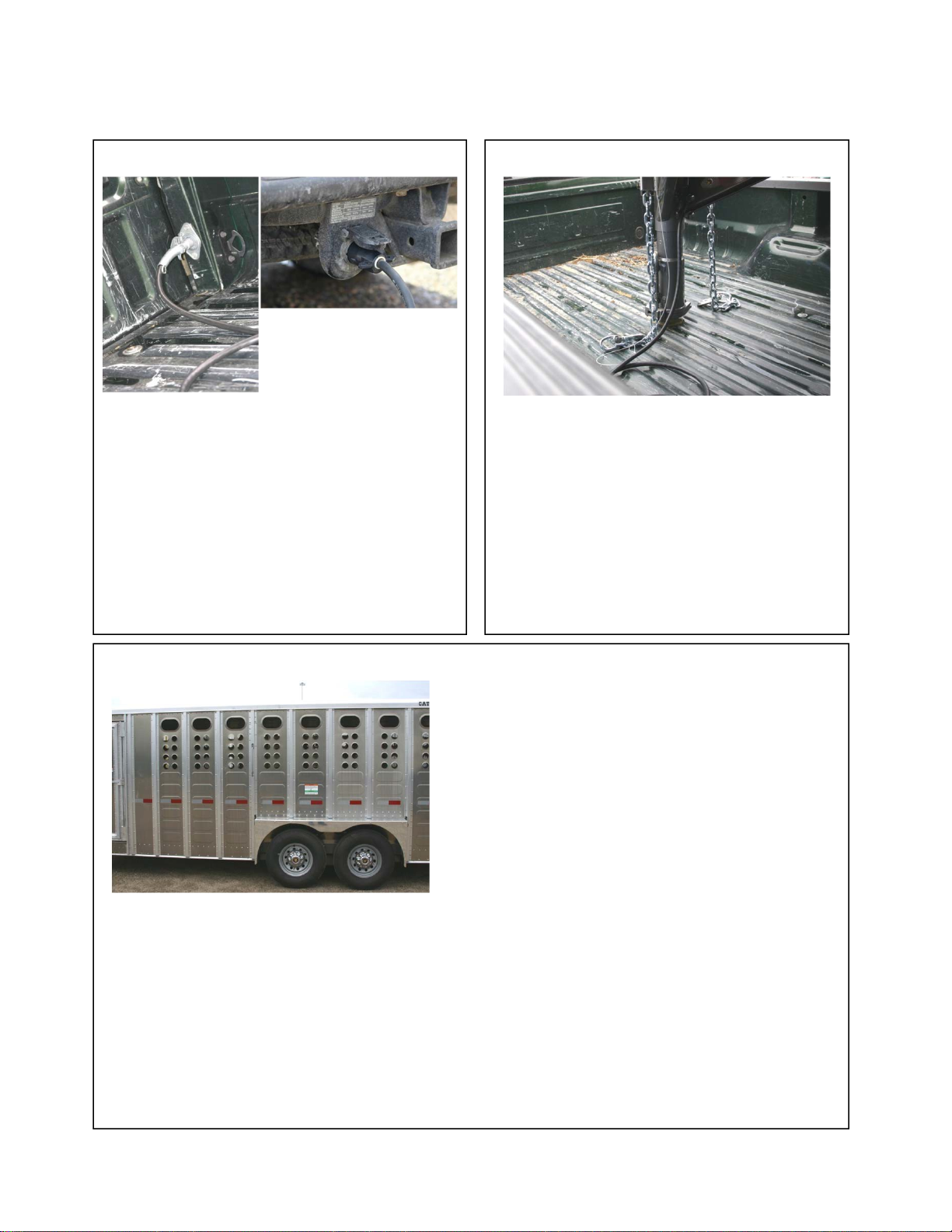
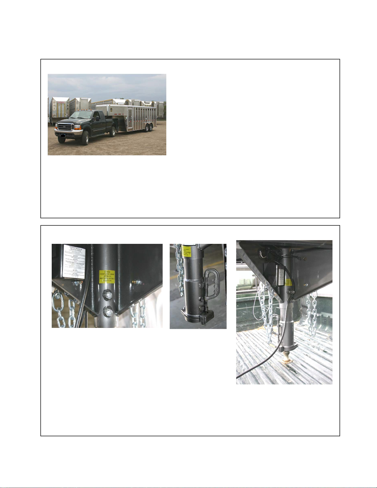
SAFETY CHAINS
COUPLER ATTACHMENT
After hook-up, check for positive engagement of
the hitch ball and coupler. Be certain that lock
handle is completely engaged before towing the
trailer. Also check to insure that coupler
adjustment set screws are torqued to 65-70 ft. lbs
The safety chains should hook
individually behind the coupler to the
attachment points in the tow vehicle (as
shown in the photo). They MUST NOT
be attached to the ball.
4-1
BEFORE TRIP INSPECTIONPROCEDURE
BRAKEAND ELECTRICALCONTROLS
BRAKE CONTROLS
Check brakes for proper operation before
each trip. On trailers with electric brakes,
fasten the breakaway switch actuating cable
securely to the towing vehicle.
Make certain
the breakaway battery is fully charged.
Your breakaway battery kit contains a tow
charger which can keep your battery charged.
The charger is hooked to the clearance light
circuit and will charge while running lights
are being used.
Connect the front receptacle and check for
proper
operation of stop lights, right / left turn
signals and running lights. Repair
malfunctioning lights prior to trip. Check and
clean all lights and reflectors. Proper
operation requires clean and positive contact
between electrical connectors. Be sure the
plug on the light cable and trailer connectors
are free of corrosion. Inspect all wiring to see
it is not frayed.
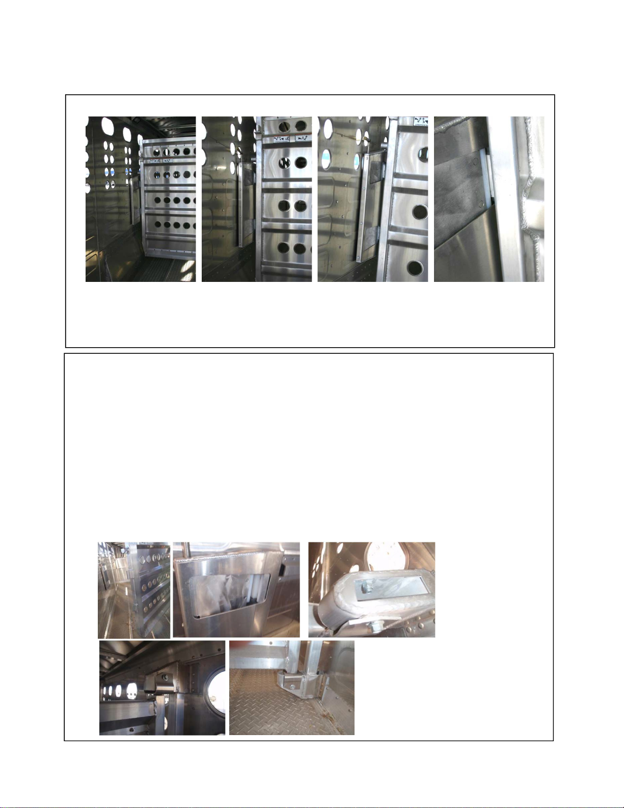
SIDE STRUCTURE
Check the trailer sides for inconspicuous damage to the top and bottom rails as well as the side
structure. Any problems observed in the side structure should be corrected immediately to
prevent the damage from extending further. Unrepaired damage could affect the safe load
carrying capacity of the side structure.
Punched side trailers are built with aluminum side skin. DO NOT use holes to hang heavy
objects on the side. DO NOT use the holes to tie animals. This could damage the side skin.
Failure to follow these procedures may result in unnecessary wear and malfunction. It may also
create difficulties with the mechanical operation of the trailer, and could possibly result in
personal injury and/or property damage.
4-2
BEFORE TRIP INSPECTIONPROCEDURE
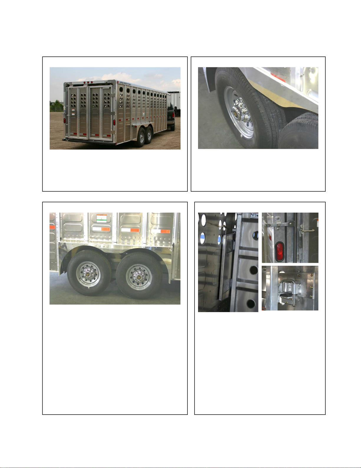
GATES
TIRES
Check tires for cuts and abrasions.
Check air pressure before each trip.
Inflate as recommended by tire
manufacture.
Before traveling, be sure that all gates are
locked in either a fully open, or fully closed
position. All roll-
up doors must be closed and
ropes secured.
WHEELS & RIMS
DOOR LOCKS
Check wheel nuts after initial 50 to 100 miles
of service. Refer to the torque requirements
for the correct procedure and specifications if
necessary. Failure to use properly matched
wheels, studs, brakes or cap nuts will result
in equipment damage and could result in
injury or death if wheel comes off.
Insufficient mounting torque can cause wheel
shimmy, resulting in damage to parts and
extreme tire wear. Excessive mounting
torque can cause studs and cap nuts to brake
and discs to crack in stud hole area.
Check all gate locks, access door locks, side
door locks and rear door locks before each
trip to insure that they are in proper working
order. Any door, gate locks or keepers
which show excessive wear should be
replaced immediately. Care should be taken
to keep the area around the do
or frame clear
of any debris or animal waste. A build-
up of
animal waste may result in
more pressure being applied to locks than
they were designed to withstand.
4-3
OPERATING INSTRUCTIONS
OPERATION OF BRAKES
Your trailer brakes are designed to work together with
your towing vehicle brakes to stop the combined load.
When one does the stopping for both, the overload
causes heat build-
up which can result in brake wear, a
direct loss of braking power and increased brake
lining wear.
Jack-knifing can occur if the tow vehicle brakes
are used alone, allowing the trailer to push the
vehicle. This can result in equipment damage and
personal injury.
Complete details for making adjustments on or replacement within your braking system can be
found in the brake manufacturer’s supplement provided with this manual.
Proper synchronization of tow vehicle to trailer braking can only be accomplished by road
testing. Follow the instructions found in the manufacturer’s supplement for correct
synchronization procedures.
OPERATION OF COUPLER
The coupler installed on your trailer is of steel pipe design,
adjustable in height to meet different vehicle hitch heights. The
coupler should be adjusted so that your trailer is level when
towed, not nose up or nose down. To adjust the coupler, back
towing vehicle under the coupler. Level your trailer using the
trailer landing gear, then loosen the two coupler set screws and
lower the inner unit over the tow vehicle hitch ball. Tighten the
coupler set screws to 65-70 foot pounds of torque. The coupler
is now set to the correct height for your vehicle.
Be certain that coupler lock handle is completely engaged
before towing the trailer.
5-1
OPERATING INSTRUCTIONS
OPERATION OF GATES
Divide gate is provided with a slam lock. Be sure that slam lock is completely engaged before
towing the trailer.
To prevent personal injury, stand clear of swinging gate until slam lock is engaged
ADJUSTMENT OF GATES
Adjustment of gate to slam lock: If your gates need to be adjusted,
1)
Locate the slam lock and gate. Latch on the gate (fig 1) must line up in the center of
catch on the slam lock (fig 2).
Decide if top latch or bottom latch is out of adjustment. Loosen up the bolts on the hinges
(fig 3, 4, 5) and tilt gate to the right to adjust the bottom latch or to the left to adjust the
top. What you are trying to accomplish is to center the latch on the gate (fig 1) to the
center of the catch (fig 2).
Once the gate is back in alignment tighten up the top and bottom bolts (fig 3, 4, 5) and
try the gate. If you need to do some fine tuning on the gate just follow the instructions
2)
3)
FIG 3
FIG 2
FIG 1
FIG 5
FIG 4
5-2

GENERALMAINTENANCE
FASTENERS
FLOOR
Your Merritt Gooseneck trailer is constructed
with aluminum tread plate floors to reduce
slipping. Never use sand or abrasive materials
for animal bedding as this will cause excessive
floor wear. The most important part of floor
maintenance is cleaning.
Floors, deck rails, coupler assemblies,
and tandem sub-
assemblies are attached
to the trailer with zinc plated and
stainless steel fasteners.
Inspect monthly that all zinc plated
fasteners are in place. If any are
missing or loose, they should be
replaced immediately.
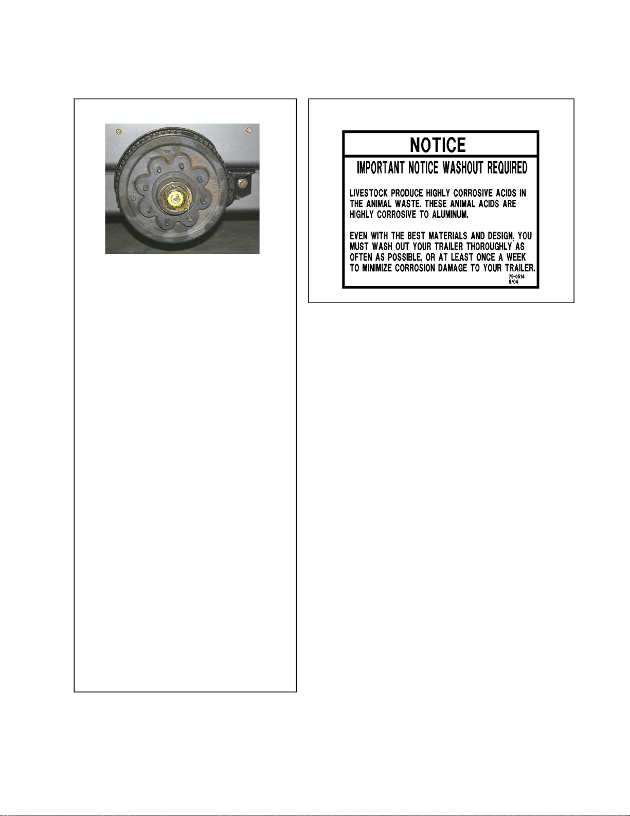
WHEEL BEARINGS
GATE AND RAMP HINGES
Wheel bearings and cups should be inspected for
corrosion or wear every 12 months or 12,000
miles. Bearing adjustment and proper lubrication
is essential to the function and reliability of your
trailer axles. Please refer to the Dexter Axle
“Operations Maintenance Service Manual” for
the proper lubricant specifications.
When new bearings are needed, they must
always be replaced in sets of a cone and a
cup.
Gate, door and ramp hinges are provided
with grease fittings. They should be
lubricated on a regular basis in order to
avoid unnecessary wear.
6-1
GENERALMAINTENANCE
GREASE SEALS
GENERAL MAINTENANCE
7,000 lb, 8,000 lb,. Torflex axles are
standard with E_Z lube spindles. This
feature allows the bearings to
periodically lube without removing hubs
from axle. Please refer to the Dexter Axle
“Operation Maintenance Service
Manual” for additional details.
The 7,000 lb, 8,000 lb. Torflex axles and
wheel bearings must be manually
lubricated. The bearings and cups should
be inspected and/or lubricated every 12
months or 12,000 miles. Please refer to
the Dexter Axle “Operation Maintenance
Service Manual” for additional details.
The 10K Torflex axles are equipped with
oil lubricated hubs, periodically check
and refill the hub as necessary with a
high quality hypoid gear oil to the level
indicated on the clear plastic oil cap. The
oiled can be filled from either the oil fill
hole, if present in the hub or through the
rubber plug hole in the cap itself. The
bearing and cups should be inspected
every 12 months or 12,000 Miles
`
6-2

BRAKES
BRAKES
See Notice: Brakes Adjustment (Page 7-2). Adjust your trailer brakes after the first 200 miles and
then after every 3,000 miles or 3 months of use. The brake drum should be inspected every 12
months or 12,000 miles. Inspect the drum surface for excessive wear or heavy scoring. If worn
more than .020”, oversized drums should be turned. The maximum re-bore should not exceed
.090”
On trailers with electric brakes, also inspect the inner surface of the brake drum that contacts the
brake magnet. If the surface is scored or worn unevenly, it should be refaced by removing not
more than .030” of material.
Check the brake magnet for wear and current draw every 6 months or 6,000 miles.
It is important that the wheel bearing bores are not contaminated by metallic chips
resulting from drum turning or re-facing. Make certain that wheel bearing cavities are
clean before reinstalling bearings seals. The presence of contaminants will cause premature
wheel bearing failure.
7-1

BRAKES
BRAKES ADJUSTMENT*
Brakes need to be adjusted (1) after the first 200 miles of
operation when the brake shoes have “seated”, (2) at 3,000
miles intervals, (3) or as use and performance requires. The
brakes should be adjusted in the following manner:
1.
Jack up trailer and secure on adequate jack stands. Check
that the wheel and drum rotate freely.
2.
Remove the adjusting hol
e cover from the adjusting slot on
the bottom of the backing plate
3.
With a screwdriver or standard adjusting tool, rotate the
star wheel of the adjuster assembly to expand the brake
drums. Adjust the brake shoe out until the pressure of the
linings against the drum make the wheel difficult to turn.
4.
Then rotate the star wheel in the opposite direction until
the wheel turns freely with a lining drag.
5.
Replace the adjusting hole cover and lower the wheel to
the ground.
6.
Repeat the above procedure on all brakes.
* This section applicable to trailers equipped with Dexter
Axles. Taken from the Dexter Axle Service Manual.
Adjusting Hole Cover
7-2
NOTICE
GOOSENECK TRAILER BRAKES
•7,000 lb axles may have manually adjusted brakes
•
Manual adjusting brakes require proper maintenance to prevent problemsfrom
developing. `
•
Effective 2018 model year all 7,000, 8,000, 10,000 lb axles have automatic forward
adjusting brakes.
•
The automatic forward adjusting brakes still require periodic inspection and
adjustment asnecessary.

WHEELS ANDTIRES
8-1
WHEELS
Wheels are a critical component of your
running gear system. When replacing the
trailer wheels it is critical to match the
capacity rating and to ensure that they are
equal or greater than the original
equipment supplied by the manufacture.
Do not attempt to repair or modify a
wheel. Even minor modifications can
have great effect. Do not install a tube
to correct a leak through the rim. If the
rim is cracked, the air pressure in the
tube may cause the pieces of the rim to
explode with great force and can cause
serious injury or death.
TORQUE REQUIREMENTS
It is extremely important to apply and
maintain proper wheel mounting torque to
your trailer axle. Torque is a measure of the
amount of tightening applied to a fastener
(nut or bolt) and is expressed as length X
force. A force of 90 pounds applied at the
end of a wrench one foot long will yield 90
foot pounds of torque. Torque wrenches are
the best method to assure that the proper
amount of torque is being applied to a
fastener.
Be sure to use only the fasteners matched to
the cone angle of your wheel (usually 60 or
90 degrees)
The proper procedure for attaching your
TORQUE wheels is as follow:
SEQUENCE 8 BOLT 1. Start all bolts or nuts by hand to prevent
cross threading.
Wheel Nut Torque Guide 2. Tighten bolts or nuts in the sequence
Nut size torque (ft. lbs.) detailed below.
1/2”-20 (Cone) 90-120 3. The tightening of the fasteners should be
9/16”-18 (Cone) 90-120 Steel done in stages. Following the recommended
9/16”-18 (Cone) 120-140 aluminum sequence, first tighten all the fasteners to 20-
5/8”-18 (Cone) (note #1) 190-210 25 ft. lb., and finally to the required torque
5/8”-18 (Flanged nut) 275-325 (One-Piece) based on the size of the wheel nut (see chart).
5/8”-18 (Flanged nut) (note #2) 140-160 (two Piece) 4. Wheel nut/bolts should be torqued before
Note #1 This is when nut is used in conjunction with the first road use and after each wheel
the reinforcing ring. removal. Check and re-torque after the
Note #2 This two piece flange nut is used on the
Alco Aluminum Dual wheel application.

WHEELS ANDTIRES
8-2
Trailers Over 10,000 Pounds GVWR
NOTE: These trailers are not required to have a tire information placard on the vehicle.
Determine the empty weight of your trailer by weighing the trailer using a public scale or other means. This step
does not have to be repeated.
Locate the GVWR (Gross Vehicle Weight Rating) of the trailer on your trailer's federal VIN Tag.
Subtract the empty weight of your trailer from the GVWR stated on the VIN label. That weight is the maximum
available cargo capacity of the trailer and may not be safely exceeded.
TIRE SAFETY
Everything Rides On It
The National Traffic Safety Administration (NHTSA) has published a brochure (DOT HS 809 361) that discusses all
aspects of Tire Safety, as required by CFR 575.6. This brochure is reproduced in part below. It can be obtained and
downloaded from NHTSA, free of charge, from the following web site:
www.nhtsa.dot.gov/cars/rules/TireSafety/ridesonit/tires_index.html
Studies of tire safety show that maintaining proper tire pressure, observing tire and vehicle load limits (not carrying
more weight in your vehicle than your tires or vehicle can safely handle), avoiding road hazards, and inspecting tires
for cuts, slashes, and other irregularities are the most important things you can do to avoid tire failure, such as tread
separation or blowout and flat tires. These actions, along with other care and maintenance activities, can also:
Improve vehicle handling, Help protect you and others from avoidable breakdowns and accidents, Improve fuel
economy, Increase the life of your tires.
This information presents a comprehensive overview of tire safety, including information on the following topics:
Basic tire maintenance, Uniform Tire Quality Grading System, Fundamental characteristics of tires, Tire safety tips.
Use this information to make tire safety a regular part of your vehicle maintenance routine. Recognize that the time
you spend is minimal compared with the inconvenience and safety consequences of a flat tire or other tire failure.
Safety First–Basic Tire Maintenance
Properly maintained tires improve the steering, stopping, traction, and load-carrying capability of your vehicle.
Underinflated tires and overloaded vehicles are a major cause of tire failure. Therefore, as mentioned above, to avoid
flat tires and other types of tire failure, you should maintain proper tire pressure, observe tire and vehicle load limits,
avoid road hazards, and regularly inspect your tires.
Finding Your Vehicle's Recommended Tire Pressure and Load Limits
Tire information and vehicle certification labels contain information on tires and load limits. These labels indicate
the vehicle manufacturer's information including: Recommended tire size, Recommended tire inflation pressure,
Vehicle capacity weight (VCW–the maximum occupant and cargo weight a vehicle is designed to carry), Front and
rear gross axle weight ratings (GAWR– the maximum weight the axle systems are designed to carry).Federal tag is
permanently attached to the vehicle near the front left side.
Understanding Tire Pressure and Load Limits
Tire inflation pressure is the level of air in the tire that provides it with load-carrying capacity and affects the overall
performance of the vehicle. The tire inflation pressure is a number that indicates the amount of air pressure

WHEELS ANDTIRES
8-3
measured in pounds per square inch (psi)–a tire requires to be properly inflated. (You will also find this number on
the vehicle information placard expressed in kilopascals (kPa), which is the metric measure used internationally.)
Manufacturers of passenger vehicles and light trucks determine this number based on the vehicle's design load limit,
that is, the greatest amount of weight a vehicle can safely carry and the vehicle's tire size. The proper tire pressure for
your vehicle is referred to as the "recommended cold inflation pressure." (As you will read below, it is difficult to
obtain the recommended tire pressure if your tires are not cold.)
Because tires are designed to be used on more than one type of vehicle, tire manufacturers list the "maximum
permissible inflation pressure" on the tire sidewall. This number is the greatest amount of air pressure that should
ever be put in the tire under normal driving conditions.
Checking Tire Pressure
It is important to check your vehicle's tire pressure at least once a month for the following reasons:
Most tires may naturally lose air over time.
Tires can lose air suddenly if you drive over a pothole or other object or if you strike the curb when parking.
With radial tires, it is usually not possible to determine under inflation by visual inspection.
For convenience, purchase a tire pressure gauge to keep in your vehicle. Gauges can be purchased at tire dealerships,
auto supply stores, and other retail outlets.
The recommended tire inflation pressure that vehicle manufacturers provide reflects the proper psi when a tire is
cold. The term cold does not relate to the outside temperature. Rather, a cold tire is one that has not been driven on
for at least three hours. When you drive, your tires get warmer, causing the air pressure within them to increase.
Therefore, to get an accurate tire pressure reading, you must measure tire pressure when the tires are cold or
compensate for the extra pressure in warm tires.
Steps for Maintaining Proper Tire Pressure
Step 1: Locate the recommended tire pressure on the vehicle's tire information placard, certification label, or in the
owner's manual.
Step 2: Record the tire pressure of all tires.
Step 3: If the tire pressure is too high in any of the tires, slowly release air by gently pressing on the tire valve stem
with the edge of your tire gauge until you get to the correct pressure.
Step 4: If the tire pressure is too low, note the difference between the measured tire pressure and the correct tire
pressure. These "missing" pounds of pressure are what you will need to add.
Step 5: At a service station, add the missing pounds of air pressure to each tire that is underinflated.
Step 6: Check all the tires to make sure they have the same air pressure (except in cases in which the front and rear
tires are supposed to have different amounts of pressure).
If you have been driving your vehicle and think that a tire is underinflated, fill it to the recommended cold inflation
pressure indicated on your vehicle's tire information placard or certification label. While your tire may still be
slightly underinflated due to the extra pounds of pressure in the warm tire, it is safer to drive with air pressure that is
slightly lower than the vehicle manufacturer's recommended cold inflation pressure than to drive with a significantly
underinflated tire. Since this is a temporary fix, don't forget to recheck and adjust the tire's pressure when you can
obtain a cold reading.

WHEELS ANDTIRES
8-4
Tire Size
To maintain tire safety, purchase new tires that are the same size as the vehicle's original tires or another size
recommended by the manufacturer. Look at the tire information placard, the owner's manual, or the sidewall of the
tire you are replacing to find this information. If you have any doubt about the correct size to choose, consult with
the tire dealer.
Tire Tread
The tire tread provides the gripping action and traction that prevent your vehicle from slipping or sliding, especially
when the road is wet or icy. In general, tires are not safe and should be replaced when the tread is worn down to 1/16
of an inch. Tires have built-in tread wear indicators that let you know when it is time to replace your tires. These
indicators are raised sections spaced intermittently in the bottom of the tread grooves. When they appear "even" with
the outside of the tread, it is time to replace your tires. Another method for checking tread depth is to place a penny
in the tread with Lincoln's head upside down and facing you. If you can see the top of Lincoln's head, you are ready
for new tires.
Wheel Alignment
A wheel alignment adjusts the angles of the wheels so that they are positioned correctly relative to the vehicle's
frame. This adjustment maximizes the life of your tires and prevents your car from veering to the right or left when
driving on a straight, level road. These adjustments require special equipment and should be performed by a qualified
technician.
Tire Repair
The proper repair of a punctured tire requires a plug for the hole and a patch for the area inside the tire that surrounds
the puncture hole. Punctures through the tread can be repaired if they are not too large, but punctures to the sidewall
should not be repaired. Tires must be removed from the rim to be properly inspected before being plugged and
patched.
Tire Fundamentals
Federal law requires tire manufacturers to place standardized information on the sidewall of all tires. This
information identifies and describes the fundamental characteristics of the tire and also provides a tire identification
number for safety standard certification and in case of a recall.
Information on Passenger Vehicle Tires
P
The "P" indicates the tire is for passenger vehicles.
Next number
This three-digit number gives the width in millimeters of the tire from sidewall edge to sidewall edge. In general, the
larger the number, the wider the tire.
Next number
This two-digit number, known as the aspect ratio, gives the tire's ratio of height to width. Numbers of 70 or lower
indicate a short sidewall for improved steering response and better overall handling on dry pavement.
R
The "R" stands for radial. Radial ply construction of tires has been the industry standard for the past 20 years.

WHEELS ANDTIRES
8-5
Next number
This two‐digit number is the wheel or rim diameter in inches. If you change your wheel size, you will have to purchase
new tires to match the new wheel diameter.
Next number
This two‐ or three‐digit number is the tire's load index. It is a measurement of how much weight each tire can
support. You may find this information in your owner's manual. If not, contact a local tire dealer. Note: You may not
find this information on all tires because it is not required by law.
M+S
The "M+S" or "M/S" indicates that the tire has some mud
and snow capability. Most radial tires have these
markings; hence, they have some mud and snow
capability.
Speed Rating
The speed rating denotes the speed at which a tire is
designed to be driven for extended periods of time. The
ratings range from 99 miles per hour (mph) to 186 mph.
These ratings are listed below. Note: You may not find this
information on all tires because it is not required by law.
• For tires with a maximum speed
capability over 149 mph, tire
manufacturers sometimes use the
letters ZR. For those with a maximum
speed capability over 186 mph, tire
manufacturers always use the letters
ZR.
U.S. DOT Tire Identification Number
This begins with the letters "DOT" and
indicates that the tire meets all federal
standards. The next two numbers or letters
are the plant code where it was
manufactured, and the last four numbers
represent the week and year the tire was
built. For example, the numbers 3197 means
the 31st week of 1997. The other numbers are
marketing codes used at the manufacturer's
discretion. This information is used to contact
consumers if a tire defect requires a recall.
Tire Ply Composition and Materials Used
The number of plies indicates the number of layers of rubber-coated fabric in the tire. In general, the greater the number of
plies, the more weight a tire can support. Tire manufacturers also must indicate the materials in the tire, which include steel,
nylon, polyester, and others.
Maximum Load Rating
This number indicates the maximum load in kilograms and pounds that can be carried by the tire.
Letter Rating
Speed Rating
Q
99 mph
R
106 mph
S
112 mph
T
118 mph
U
124 mph
H
130 mph
V
149 mph
W
168* mph
Y
186* mph
Table of contents


