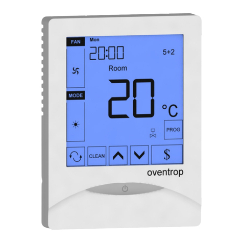
merten MEG6212-04 Series User manual

V6212-581-00 09/09
Push-buttonplus withroom temperaturecontrol unitKapitel3:Taster3.1TasterPlus© Merten2005V6212-581-0009/09
System M
System M
– You have to complete the push-button plus 2-gang
with a design frame System M.
– You have to complete the push-button plus 4-gang
with a design frame System M without central bridge
piece(art. no. 4788.., 4858.., 4868.., 4878.., 5158..,
4888).
¼DANGER
Risk of fatal injury from electrical current.
The unit may only be installed and connected by
skilled electicians. Observe the regulations valid
in the country of use, as well as the valid KNX
guidelines.
The push-button plus with room temperature con-
trol unit (reffered to below as the push-button) gives
you four (push-button 2-gang) or eight (push-button 4-
gang) operating surfaces. The keys can be set individu-
ally to perform various functions. Furthermore a room
temperature control unit is integrated, which allows you
to control temperature in various different ways.
Functions of the push-button:
– Switching, toggling, dimming, blind control
– Szenenfunktion
– Communication and disable functions
– Time control with synchronisation, reading external
temperature, fan control
Functions of the room temperature control unit:
– Heating/cooling with 1 controller output
– Heating/cooling with seperated controller outputs
– Heating/cooling with 2 controller outputs
The push-button can directly be connected to the KNX
and is parameterised by the electrical installer via the
KNX-Tool-Software (ETS).
Push-button plus with room
temperature control unit
Operating instructions
Push-button 2-gang plus with room
temperature control unit
Art. no. MEG6212-03../MEG6212-04..
Push-button 4-gang plus with room
temperature control unit
Art. no. MEG6214-03../MEG6214-04..
Necessary accessories
For your safety
Getting to know the push-button
ende
Blind
Lighting
ON OFF
Present
Absent
Blind
Lighting
ON OFF
Ventilation
Scope of delivery
Getting to know the keypad
The push-buttons opposite each other can be config-
ured as either individual push-buttons or a push-button
pair. The push-buttons are programmed with various
functions depending on the pre-setting.
For 4-gang push-button only:
The 4-gang push-button is equipped with an IR receiver,
with which you can control the push-button with any IR
remote control. Pressing push-buttons 1-8 on the remote
control activates the function of the corresponding push-
button. Push-buttons 9 and 10 of the remote control have
a direct effect on display push-buttons 9 and 10.
In order for the integrated room temperature control unit
to work in the best way, you should keep in mind the fol-
lowing when selecting the right installation side:
APush-button
BCover
CFoil strip
DSafty screw
ESticker (only push-button 4-gang)
Connections, displays and operating
elements
1 - 8: Function keys
9 + 10: Function keys for display
ADisplay
BLED
CIR receiver
DStaus LED
Mounting side
ABC E
++
++++
+
D
1
3
5
7
2
4
6
8
A
D
C
B1
3
2
4
910 910
110...160 mm
Sources of interference
Push-button 2-gang and 4-gang
Only push-button 4-gang
1Set the push-button to programming state
2Load the physical address and application from the
ETS into the push-button: The red programming
LED goes out.
|Note for the electrician
Make sure that you note the settings you have
made in the ETS which are important for the user
in the configuration table (see „Pre-settings ta-
ble“), because not all parameters that can be set
are shown in the display of the push-button.
Mounting the push-button
Operating the push-button
1
23
=
Push-button 2-gang and 4-gang
½CAUTION
The device could become damaged.
Before removing the push-button, check whether
it is secured with protection against theft. Always
remove the protection against theft before remov-
ing the push-button.
Opening the labelling field
Creating labelled foil strips
You can also create and print corresponding foil strip
templates with any layout program.
Size specifications for foils (in mm):
Consult the operating instructions of your printer to find
out which type of foil strips you can print.
|Only use the coloured foil strips enclosed as the
base, since this ensures that the push-button
LEDs under the labelling field can shine through.
|Two versions of coloured foil strips are provided:
one with a recess in the middle for the IR receiver,
and one without a recess. If you want to control
the push-button via an IR remote control, you
have to use the coloured foil strip with recess. Al-
ways only use one of the two coloured foil strips.
Closing the labelling field
Anti-theft protection
Dismantling the push-button
Labbelling the push-button
Push-button Height Width Thickness
2-gang 24,9 23 max. 0,15
4-gang 96,2 23 max. 0,15
12
3
12
1 2
When installing the push-button, the electrician defines
various settings that are necessary so you can use the
push-button correctly. Most of the explanations provided
on the following pages depend on these settings. The
electrician enters the settings in question in a table for
you (see table „pre-settings”).
|If you come across this symbol when reading,
it means that you can look up the corresponding
value in the table.
With the integrated room temperature control unit, you
can control the temperature in various different ways.
You can read and set important information on the dis-
play:
• Setpoint temperature
• Operating mode (comfort, standby, night, etc.)
• Working day/holiday
• Display mode (setpoint temperature, actual tempera-
ture, date etc.)
•Backgroundlighting
• Setting the time/switching time
Getting to know the display
You will see the following symbols on the display:
Pre-settings
Preface room temperature control unit/
display
Comfort mode or working day. The room tem-
perature is adjusted to the set comfort setpoint
temperature .
The flashing symbol means that the comfort ex-
tension is active.
Standby mode or holiday. The room tempera-
ture is adjusted to the set standby setpoint tem-
perature .
Night operation. The room temperature is ad-
justed to the set night setpoint temperature .
Time control is active.
Constant display: The time has been synchro-
nised.
Flashing display: The time has not been syn-
chronised; the displayed time may not be accu-
rate.
Alarm, symbol flashing. For 4-gang push-but-
ton: Additional acoustic warning sound possi-
ble .
1 2 3 4
5 6 7 Weekday display .
In combination with : Fan speed
Menu command „Setting the background light-
ing“ is activated.
Fan.
Heating control mode is active or controller re-
quires power.
Cooling control mode is active or controller re-
quires power.
Display under „Heating“ or „Cooling“ symbol.
- For heating or cooling:
„1“: Setpoint temperature has not yet been
reached. The controller is heating or cooling.
„2“: Level 2 is activated(display only if two-step
heating/cooling is set.
- For heating and cooling: Two modes are avail-
able: Manual or automatic
°C Temperature display in degrees Celsius
°F Temperature display in degrees Fahrenheit
88:88 Time display or value display
Getting to know the control menu
There is a control menu for selecting the individual func-
tions of the room temperature controller.
A rocker is integrated in the cover of the display. It has
three contacts: left, centre and right. With these push-
buttons, you can access the control menu, scroll back-
wards and forwards and change individual values.
Overview of the menu structure
*Long push-button action = approx. 5 s
**Short push-button action = approx. 1 s
|If you don‘t press any push-button within a period
of about one minute, the room temperature con-
trol unit automatically returns to the standard dis-
play. The values that were set before the control
menu was opened are restored; any changes
that you may have made are not saved. Ex-
ception: The temperature is saved directly.
Push-button action Function triggered
Center –
Long push-button action*
Select menu
Save
Return to standard display
Center –
Short push-button action** Select next menu com-
mand
Left/Right –
Short push-button action** Change value
t2.1 ... t2.4
t1.1... t1.4
Setpoint
temperature Operation mode
Workday/
leisure day
Display mode
Standard Display
(current temp.)
edit hour
edit minutes
Time/
switching time
Display backlight

V6212-581-00 09/09
Standard display
Here you see an example of the standard display:
• „Comfort“ operating mode
• Actual temperature
• Heating is active in order to reach the comfort set-
point temperature .
• is constantly displayed: The time has been syn-
chronised with the time switch (e.g. year time switch
REG-K). Clock symbol flashes: The time has not (yet)
been synchronised.
•Weekdaydisplay3= Wednesday
|Note that the display of the weekday depends on
the pre-settings. The electrician has set ,
a specific weekday to 1. In some countries the
first day of the week is not Monday, but Sunday,
for example. The other numbers have different
meanings accordingly (e.g., 2 = Monday,
3 = Tuesday etc.).
Setting the setpoint temperature
The electrician has specified three setpoint tempera-
tures ( for both heating and cooling):
• for comfort mode
• for standby mode
• for night operation
|You see the setpoint temperature of the current
operating mode. You can only change this set-
point temperature. In order to change the setpoint
temperature of another operating mode, you first
have to switch the operating mode (see „Setting
the operating mode“).
|The electrician specified , within which limits
this value can be changed (for example, within a
minimum of 16 °C up to a maximum of 26 °C). You
cannot set any value below or above these limit
values. If the electrician made the appropriate
setting , the 4-gang push-button emits a warn-
ing sound as soon as you attempt to exceed
these limit values.
Setting the room temperature control
unit/display view
1x 5 s
+ 0,5°- 0,5°
1x 5 s
1
2
=
Setting the operating mode
• b 0 = comfort mode
Select this operating mode if you are staying in the
room. The heating is set to the comfort setpoint tem-
perature (e.g. 21 °C ).
• b 1 = standby mode
Select this operating mode when you are not in the
room over a longer period of time. The heating is set to
the standby setpoint temperature (e.g. 18 °C ).
• b 2 = night operation
The heating is set to the night setpoint temperature
(e.g. 15 °C ).
• b 3 = comfort extension (flashes)
Select this operating mode if you want to suppress
night operation temporarily. The heating is set to the
comfort setpoint temperature (e.g. 21 °C ).
|The electrician may have set , the times at
which the operating mode switches automatically
from night operation to comfort mode and vice
versa.
Setting the working day/holiday
• h 0 = holiday
•h1=workingday
1
1x 5 s
2
1x 1 s
+
-
1x 5 s
=
1
1x 5 s
2
2x 1 s
1x 5 s
=
Setting the display mode
|With the display mode, you can select which val-
ues you want to see in the display.
• d 0 = actual temperature (without decimal point)
• d 1 = setpoint temperature (to 0.5 degree accuracy)
• d 2 = temperature from external temperature sensor
•d3=date
•d4=time
• d 5 = fan speed
• d 6 = date and time in alternation
• d 7 = date, time and fan speed in alternation
• d 8 = actual and setpoint temperature in alternation
• d 9 = actual/setpoint temperature and time in alterna-
tion
• d 10 = actual/setpoint temperature and fan speed in al-
ternation
• d 11 = temperature from external temperature sensor
and actual temperature
• d 12 = temperature from external temperature sensor,
actual temperature and time in alternation
• d 13 = actual/setpoint temperature, date and time in al-
ternation
• d 14 = actual/setpoint temperature, fan speed and
time in alternation
• d 15 = emperature from external temperature sensor,
actual temperature, fan speed and time in alternation
Setting the background lighting
1
1x 5 s
2
3x 1 s
+-
1x 5 s
=
1
1x 5 s
2
4x 1 s
4
+
1 = 10 =...
=
1x 5 s
-
3
Setting the internal clock time and switching times
|If the time is updated by an external time switch,
the updated time is displayed here. If you change
this time manually, it will be overwritten again by
the time switch during the next update.
|You can only use the control menu to adjust the
switching times which have been pre-pro-
grammed via the ETS. Switching times which are
not defined in the ETS are shown when they are
called up in the display with „--:--“ and cannot be
set using the push-buttons on the display.
•t 0 = time (either transmitted from the external time
switch or from the internal clock)
•t 1.1 bis t 1.4 = time channel 1, switching time 1-4
•t 2.1 bis t 2.4 = time channel 2, switching time 1-4
3Press central push-button and hold : he hour dis-
play for the selected time/switching time starts to
flash.
4Press the left or right push-button on the display:
Set the hours as desired
5Press the central push-button briefly : The minute
digits now flash.
6Press the left or right push-button on the display:
Set the minutes as desired.
7Press the central push-button briefly: The set time
(t...) appears again.
8Press the central push-button briefly again: Save
the desired new setting.
|Synchronise the time via an external time switch
to guarantee precision over a long period of time.
Selecting the setpoint temperature or operating
mode directly
The electrician specified , whether you can access
and adjust the setpoint temperature or the operating
mode directly using the right/left push-button, or whether
none of these functions is activated.
11 x push-button left/right – short push-button ac-
tion.
The menu command „Set setpoint temperature“ or „Set
operating mode“ is displayed with the last set value.
Change the value by pressing the left or right push-but-
ton on the display. The value is saved directly; you don‘t
have to save it separately. After approx. 5 s, the room
temperature control unit returns automatically to the
standard display.
1
1x 5 s
2
5x 1 s
+-
1x 5 s
=
Push-button assignment
Time control channel 1
Time control channel 2
Alarm functions
Setpoint adjustment valid until:
Operation mode change / Permanent
Week starts (1): on Fri / Sat / Sun / Mon
Direct selection: Setpoint temperature / Operation
mode / None
Other display views
APL. Application not loaded or faulty
E 2 Heating setpoint temperature = cooling setpoint
temperature
E 3 ETS application is not compatible
E 4 Upper control value range = lower control value
range
E 5 FRAM error
E 6 Error in temperature sensor
E 7 STACK error
E 8 RAM error
E 9 Buffer error
Presettings table
Push-button 1 _____________________________
Push-button 2 _____________________________
Push-button 3 _____________________________
Push-button 4 _____________________________
Push-button 5 _____________________________
Push-button 6 _____________________________
Push-button 7 _____________________________
Push-button 8 _____________________________
Switching
time
1 234
Time ___:___ ___:___ ___:___ ___:___
Function: _______________________________
Switching
time
1 234
Time ___:___ ___:___ ___:___ ___:___
Function: _______________________________
Alarm sounds if actual temperature is less than
the frost protection temperature or
Alarm sounds if the setpoint adjustment limit is
exceeded
Others:
____________________________________
Heating setpoints in °C/°F Adjustment limit in °C/°F
Comfort: ______ min: _____ max: _____
Standby: ______ min: _____ max: _____
Night: ______ min: _____ max: _____
Heating setpoints in °C/°F Adjustment limit in °C/°F
Comfort: ______ min: _____ max: _____
Standby: ______ min: _____ max: _____
Night: ______ min: _____ max: _____
Frost
protection: ______ min: _____ max: _____
Heat
protection: ______ min: _____ max: _____
If you have technical questions, please contact the Cus-
tomer Care Center in your country.
www.schneider-electric.com
This product must be installed, connected and used in
compliance with prevailing standards and/or installation
regulations. As standards, specifications and designs
develop from time to time, always ask for confirmation of
the information given in this publication.
Technical data
Power supply: via KNX
Connection: Bus connecting terminal
Display elements
Push-button
2-/4-gang: 1x Display
1x operational LED
Push-button 2-gang: 4x Status LED
Push-button 4-gang: 8x Status LED
Piezo buzzer
Operating elements
Push-button
2-/4-gang: 3 push-buttons to navigate
menu
Push-button 2-gang: 4 push-buttons
Push-button 4-gang: 8 push-buttons
IR receiver
(angle of reception: 60°)
Measuring range: 0 to 40 °C
Measuring accuracy: ± 1 K, depending on installa-
tion site; Offset can be config-
ured
Controller type: 2-step
Continuous PI controller
Switching PI controller (PWI)
Controller mode: Heating with 1 controller
output
Cooling with 1 controller out-
put
Heating with 2 controller out-
puts
Cooling with 2 controller out-
puts
Heating and cooling with
separate controller outputs
2-step heating with 2 controller
outputs
2-step cooling with 2 controller
outputs
2-step heating and 2-step
cooling with 4 control outputs
Type of protection: IP 20
Schneider Electric Industries SAS

© 2009 Merten by Schneider Electric 1
Push-button, 4-gang plus with room temperature control unit and IR receiver
Multifunction with RTCU and FanCoil 1817/1.0
Settings in ETS
Selection in the product database
Selection in the product database
|The application can only be operated with ETS3.
Settings in ETS
Manufacturer: Merten
Product family: 1.5 Multifunction Push Button
Product type: 1.5.07 System M with IR
Range name: Multifunction with RTCU and FanCoil 1817/1.0
Media type: Twisted Pair
Product name: Push-button, 4-gang plus, room temp. control + IR
Order number: MEG6214-03xx, MEG6214-04xx
Manufacturer: Merten
Product family: 2.3 Push Button, 4-gang
Product type: 2.3.15 System M
Range name: Multifunction with RTCU and FanCoil 1817/1.0
Media type: Twisted Pair
Product name: Push-button, 4-gang plus, room temp. control + IR
Order number: MEG6214-03xx, MEG6214-04xx
Manufacturer: Merten
Product family: 7.1 Heating/Single Room Thermostat
Product type: 7.1.17 System M thermostat
Range name: Multifunction with RTCU and FanCoil 1817/1.0
Media type: Twisted Pair
Product name: Push-button, 4-gang plus, room temp. control + IR
Order number: MEG6214-03xx, MEG6214-04xx
Manufacturer: Merten
Product family: 1.5 Multifunction Push Button
Product type: 1.5.02 System Design with IR
Range name: Multifunction with RTCU and FanCoil 1817/1.0
Media type: Twisted Pair
Product name: Push-button, 4-gang plus, room temp. control + IR
Order number: MEG6214-40xx, MEG6214-41xx
Manufacturer: Merten
Product family: 2.3 Push Button, 4-gang
Product type: 2.3.14 System Design
Range name: Multifunction with RTCU and FanCoil 1817/1.0
Media type: Twisted Pair
Product name: Push-button, 4-gang plus, room temp. control + IR
Order number: MEG6214-40xx, MEG6214-41xx
Manufacturer: Merten
Product family: 7.1 Heating/Single Room Thermostat
Product type: 7.1.16 System Design thermostat
Range name: Multifunction with RTCU and FanCoil 1817/1.0
Media type: Twisted Pair
Product name: Push-button, 4-gang plus, room temp. control + IR
Order number: MEG6214-40xx, MEG6214-41xx
Application overview
Application Vers. Functions
Multifunction with
RTCU and FanCoil
1817/1.0
1Push-button functions:
Sendtogglecommands-1bit,1byte
Send switching commands - 1 bit,
1byte
Dimming
Blind control
Send edge commands - 1 bit, 2 bit (pri-
ority), 4 bit, 1 byte (distinction between
short/long operation)
Send edge commands - 2 byte (dis-
tinction between short/long operation)
Parameterise 8-bit linear regulator
Retrieve scenes
Setpoint adjustment
Operation mode
Set the parameters for the disable
function for push-buttons
Set the parameters for scenes in the
scene module
Signal function
Time control
Room temperature control unit
Display external temperature in display
Control and display the fan speed
Behaviour when bus voltage recovers/
bus voltage fails

2© 2009 Merten by Schneider Electric
Push-button, 4-gang plus with room temperature control unit and IR receiver
Multifunction with RTCU and FanCoil 1817/1.0
Multifunction application with RTCU and FanCoil 1817/1.0
Function overview
This application provides you with the following func-
tions:
• Temperature control with various display options
• Scene function
• Disable function for push-buttons
• Time control
•Valvecontrol
• Push-button functions
All buttons can be assigned different functions inde-
pendently. You can do the following:
• Switch and toggle
• Dim
• Control blinds
• Save and retrieve scenes
• Select a linear regulator function
• Save edge functions
• Adjust setpoints
• Access operation modes and toggle between them
The status LEDs can also be utilised independently of
one another and in a wide variety of ways.
Group addresses
Group addresses are managed dynamically. Maximum
number of group addresses and assignments: 254 ad-
dresses, 255 connections
Notes on this documentation
This application enables you to implement a multitude
of functions with the push-button. However, which func-
tions are possible in each individual case depends on
the KNX devices being controlled (e.g. dimming actua-
tors, switch actuators etc.). The functions described
here therefore show only the settings for this push-but-
ton.
|Many parameters and their settings are depend-
ent on the settings you have already made for oth-
er parameters. This means that some parameters
will appear or disappear and the values available
for selection will change according to settings you
have already made. These dependencies have
not been shown in the table for reasons of clarity.
All settings are always shown.
|Configurable times (staircase timer, ON delay,
OFF delay, cyclic intervals etc.) are set via the
base and factor parameters. The actual time is giv-
en by the multiplication of the two values. Exam-
ple: Base = 1 second * factor = 3 gives 3 seconds.
|The bold values in a table are the values set dur-
ing factory configuration.
Before you start, specify certain basic settings on the
"General" tab. You can specify the following:
• Whether the operational LED switches off or displays
that the device is operating.
• Whether a push-button emits a sound when activated.
• Which remote control IR range (infrared range) the
push-buttons react to.
• How the date and time are received.
• Whether and how the time is sent cyclically to the bus.
• How long the push-button's start-up delay should be
after bus voltage recovery.
General settings for date and time
Here you set whether the date and time are received by
two communication objects (3 byte each) or by only one
communication object. In the latter case, there is an
8byteobjectavailable.
If you send the time cyclically to the bus, you either have
an output object with 3 byte or one with 8 byte, depend-
ing on which format you selected.
For further details about time control, synchronisation
and the master-slave function, see the "Time control"
chapter.
Multifunction application with RTCU and
FanCoil 1817/1.0
Basic settings
Ge n e r a l
Parameter Settings
Switch on operational LED Yes
No
Switch on acoustic push-button
acknowledgement
Yes
No
IR range IR range 1-10
IR range 11-20
IR range 21-30
IR range 31-40
IR range 41-50
Push-button 1/2 IR channel 1/2, 11/12, 21/22,
31/32, 41/42
Push-button 3/4 IR channel 3/4, 13/14, 23/24,
33/34, 43/44
Push-button 5/6 IR channel 5/6, 15/16, 25/26,
35/36, 45/46
Push-button 7/8 IR channel 7/8, 17/18, 27/28,
37/38, 47/48
Left / right menu button = IR channel 9/10, 19/20, 29/30,
39/40, 49/50
Receive date and time In one communication object
In two communication objects
Send time cyclically No
Every minute
Every hour
Daily
Format of sent time Date/time format (8 byte)
Time format (3 byte)
Device's start-up delay in s (0-255) 2-255, 4

© 2009 Merten by Schneider Electric 3
Push-button, 4-gang plus with room temperature control unit and IR receiver
Multifunction with RTCU and FanCoil 1817/1.0
Setting the display
Start-up delay
The start-up delay is the time delay between the bus
voltage recovery and the device's functional start. Set a
time after which the current values can be read by other
KNX devices.
Communication objects
You can select the following communication objects:
Here, you set the display options and display functions:
• You can disable the control menu so that the menu
buttons cannot be used to make further changes to
the settings.
• You use the display mode to specify which values you
want to display on the basic display (actual tempera-
ture, setpoint temperature, time, date, external tem-
perature and fan speed). You can display these
values either individually or in alternation. You can
also set the display rhythm for alternating displays.
The display mode can also be set using the control
menu on the push-button.
• For the weekday display, you can set day "1". This
means that the first weekday can be defined as: Fri-
day, Saturday, Sunday or Monday. Each weekday is
then shown in the display with a different number ac-
cordingly.
• Time format and unit of temperature display (Celsius/
Fahrenheit).
• The background lighting on the display can either be
switched off or on at all times, or can be switched on
during operation. You can also set the persistence pe-
riod and the brightness of the background lighting.
|The parameters for the background illumination
and display mode can be changed using the menu
buttons on the push-button (see operating instruc-
tions).
If you use room temperature control ("Control general"
tab), additional possible settings appear:
• You can specify whether or not the operation mode
can be changed when the frost or heat protection op-
eration mode is activated.
• "Access menu setpoint temperature/operation mode
directly" Here, you specify which operation mode you
want to select with a short push of a button on the
menu buttons. You can choose between the control
menu "Set setpoint temperature" or "Set operation
mode".
• On the display, a symbol can show either the current
controller status or whether heating or cooling is acti-
vated.
Function Object name Type Prio Flags Behaviour
Time con-
trol
Date object input 3 byte Low WC Receive
Time con-
trol
Time object input 3 byte Low WC Receive
Time con-
trol
Date/time object
input
8 byte Low WC Receive
Time con-
trol
Date/time object
output
8 byte Low CT Transmit
Time con-
trol
Time object out-
put
3 byte Low CT Transmit
Setting the display
Display heating and cooling symbol = shows current con-
troller status
Display Type of control
Heating active, correcting variable ≠0
Cooling active, correcting variable ≠0
12
(below the
symbols)
1 = Heating/cooling active, correcting variable ≠0
For two-stage heating/cooling
1 = Basic level active, correcting variable ≠0
2 = Basic level and additional level active, correcting
variable ≠0
-- Insensitive zone, correcting variables = 0
Display heating and cooling symbol = shows heating/cool-
ing
Display Type of control
Heating
Cooling
12
(below the
symbols)
1 = Heating/cooling active, correcting variable ≠0
For two-stage heating/cooling:
1 = Basic level active, correcting variable ≠0
2 = Basic level and additional level active, correcting
variable ≠0

4© 2009 Merten by Schneider Electric
Push-button, 4-gang plus with room temperature control unit and IR receiver
Multifunction with RTCU and FanCoil 1817/1.0
Use signal function
The signal function enables the push-button to display
various states to you by means of:
• The bell symbol in the display
• Flashing status LEDs or
• Acoustically
The following states can be displayed:
• The specified limits for setpoint adjustment have not
been reached or have been exceeded.
• The preconfigured value of the actual temperature
has not been reached or has been exceeded.
The acoustic signalling ends after a parameterised time
(1 to 254 seconds) or once the actual temperature is
back within the set range.
When a signal is issued, a "1" is transmitted to the bus
via the "Feedback object output", and a "0" is transmit-
ted at the end. The "Feedback object input" can (for ex-
ample) be set to "1" by another sensor and the push-
button reacts as parameterised.
|With the setting "Acoustic signal stops - after a pa-
rameterised time", the acoustic signal only sounds
for the parameterised duration. However, the visu-
al display continues until the signal ends. You can
acknowledge the signal by pressing a menu but-
ton. It is also possible to acknowledge the signal if
an alarm is triggered via the feedback object.
|With the setting "Acoustic signal stops - if actual
temp. is within limits again", the signal cannot be
acknowledged. The acoustic and visual signalling
remain until the actual temperature is back within
the parameterised limits. It is not possible to ac-
knowledge the signal when the alarm is triggered
via the feedback object.
Display
Parameter Settings
User menu enabled Yes
No
Adjust operation mode during
frost / heat protection
Yes
No
Set display mode (multiple
names appear during the
change)
Actual temperature
Setpoint temperature
External temperature
Date
Time
Fan speed
Date/time
Date, time, fan speed
Actual temperature, setpoint tem-
perature
Actual temperature, setpoint tem-
perature, time
Actual temperature, setpoint tem-
perature, fan speed
External temperature, actual tem-
perature
External temperature, actual tem-
perature, time
Actual temperature, setpoint tem-
perature, time
Actual temperature, setpoint tem-
perature, fan speed, time
External temperature, actual tem-
perature, fan speed, time
Display rhythm 3 s - 10 s, 5 s
Time display 00:00 ...23:59
01:00 ...12:59 (AM/PM)
Access menu setpoint tempera-
ture/operation mode directly
(menu buttons)
No
Setpoint adjustment
Operation mode changed
Display heating and cooling
symbol
Shows the current controller status
Shows heating/cooling
Unit of temperature display °C, °F
Display "1" corresponds to Friday
Saturday
Sunday
Monday
Switch on background lighting No
Yes
During operation + persistence
Persistence period in s (1-254) 1-254, 10
Set brightness
(1 = very dark / 10 = very bright)
1-10, 5
Use signal function
Signal function
Parameter Settings
Use signal function Yes
No
Set signal function
Report if the limits of setpoint
adjustment are reached
Yes
No
Type of signal Only flashing display
Flashing display and acoustic
The acoustic alarm stops After a parameterised time
When actual temperature is within
the limits again
Reporting time in s (1-254) 1-254, 60
Report if actual temperature is
higher than
20.0 = 68.0 °F to
40.0 °C = 104.0 °F,
No,
20.0 °C = 68.0 °F
Report if actual temperature is
lower than
0.0 = 32.0 °F to
19.0 °C = 66.2,0 °F,
No,
3.0 °C = 37.4 °F

© 2009 Merten by Schneider Electric 5
Push-button, 4-gang plus with room temperature control unit and IR receiver
Multifunction with RTCU and FanCoil 1817/1.0
Push-button information
Communication objects
You can select the following communication objects:
On the “Push-button info” tab you can see which push-
button names in ETS correspond to which push-but-
tons on the device. The names assigned cannot be
changed.
Each time the button is pressed, the 1-bit object type
first inverts the object value and then transmits it to the
bus, in other words making a “0” into a “1”. If the same
button is pressed again, the “1” turns back into a “0”.
The device is thus switched on and off alternately. This
switching behaviour is called “toggling”.
For 1-byte object types, you can set two values, which
are transmitted alternately after each press of the but-
ton.
An update or change to the object values is possible via
the bus when another sensor switches the actuator
(e.g. via a two-way circuit or a central command). To
prevent “incorrect” toggling, the state of the actuator
(“1” or “0”) must be tracked in the push-button. To do
this, connect the group address of the second sensor to
the switch/value object of the push-button.
Two objects (1 bit / 1 byte) can also be transmitted in
any combination when the push-button is pressed.
Status indication
The status LED can:
• Be switched on or off continuously.
• Light up when pressed (for a long period), and go out
when released.
•Flash.
• Display the status of the switch/value object. When
the 1 byte object type is used, the LED lights up if val-
ue 1 is greater than zero.
• Display the status of the status feedback object.
Parameters
Function Object name Type Prio Flags Behaviour
Signal
function
Feedback object
input
1 bit Low WC Receive
Signal
function
Feedback object
output
1 bit Low CT Transmit
Push-button information
Push-button info
Parameter
Push-button 1 = Upper left push-button
Push-button 2 = Upper right push-button
Push-button 3 = Upper left middle push button
Push-button 4 = Upper right middle push button
Push-button 5 = Lower left middle push button
Push-button 6 = Lower right middle push button
Push-button 7 = Lower left push-button
Push-button 8 = Lower right push-button
Left menu button = Left push-button next to display
Right menu button = Right push-button next to display
Sending toggle commands - 1-bit, 1-byte
Push-button X
Parameter Settings
Select push-button function Toggle
Parameter Settings
Number of objects One
Two
Object A / Object B 1 bit
1 byte in steps 0 % - 100 %
1 byte continuous 0-255
Value 1 100 %, 90 %, 80 %, ..., 0 %,
25 %, 75 %
255, 254, 253, ...0
Value 2 0 %, 10 %, 20 %, ... 100 %,
25 %, 75 %
0, 1, 2, 3, ... 255

6© 2009 Merten by Schneider Electric
Push-button, 4-gang plus with room temperature control unit and IR receiver
Multifunction with RTCU and FanCoil 1817/1.0
Sending switching commands - 1-bit, 1-byte
Communication objects
You can select the following communication objects:
When a push-button is pressed, the following values
can be sent via the switch/value object
• An ON or OFF telegram
• 1 byte values in steps (0 % - 100 %)
• 1 byte values, infinitely adjustable (0-255)
• Two objects at the same time (1-bit, 1-byte) in any
combination
Status indication
The status LED can:
• Be switched on or off continuously.
• Light up when pressed (for a long period), and go out
when released.
•Flash.
• Display the status of the switch/value object. When
the 1 byte object type is used, the LED lights up if val-
ue 1 is greater than zero.
• Display the status of the status feedback object.
Parameters
Trigg er status LE D Swi t c hed on
Switched off
From switch/value object A
From switch/value object B
From status feedback object
Operation = ON / release = OFF
Long operation = ON / release = OFF
Flashes
Flashes when switch/value object A not equal
to 0
Flashes when switch/value object B not equal
to 0
Flashes when switch/value object A equals 0
Flashes when switch/value object B equals 0
Flashes when status feedback object equals 1
Flashes when status feedback object equals 0
Operation = flash / release = OFF
Long operation = flash / release = OFF
Function Object name Type Prio Flags Behaviour
Push-button X Switch object A/B 1 bit Low WCT Transmit/
receive
Push-button X Value object A/B 1 byte Low WCT Transmit/
receive
Push-button X Status feedback
object
1 bit Low WC Receive
Parameter Settings Sending switching commands -
1-bit, 1-byte
Push-button X
Parameter Settings
Select push-button function Switching
Parameter Settings
Number of objects One
Two
Object A / Object B 1 bit
1 byte in steps 0 % - 100 %
1 byte continuous 0-255
Value ON telegram
OFF telegram
100 %, 90 %, 80 %, ..., 0 %,
25 %, 75 %
255, 254, 253, ...0
Trigger status LED Switched on
Switched off
From switch/value object A
From switch/value object B
From status feedback object
Operation = ON / release = OFF
Long operation = ON / release = OFF
Flashes
Flashes when switch/value object A not equal
to 0
Flashes when switch/value object B not equal
to 0
Flashes when switch/value object A equals 0
Flashes when switch/value object B equals 0
Flashes when status feedback object equals 1
Flashes when status feedback object equals 0
Operation = flash / release = OFF
Long operation = flash / release = OFF

© 2009 Merten by Schneider Electric 7
Push-button, 4-gang plus with room temperature control unit and IR receiver
Multifunction with RTCU and FanCoil 1817/1.0
Dimming
Communication objects
You can select the following communication objects: You can use the dimming function for the following:
• Dim brighter and darker using one push-button (sin-
gle-button dimming)
• Either dim brighter or darker. You need a second
push-button to dim in the other direction (two-button
dimming).
Status indication
The status LED can:
• Display the status of the switch object
• Light up when pressed (for a long period), and go out
when released
• Be on or off continuously
•Flash
• Display the status of the status feedback object
Common parameters for single-button and two-
button dimming
You can use the corresponding push-button to switch
the light on or off (brief press) or dim it (longer press, the
exact period can be parameterised). When switching
takes place, an ON/OFF telegram is sent via the switch
object. When dimming, dimming up or dimming down is
carried out via the 4-bit dimming object; the parameters
for the dimming steps can be set. You can also transmit
the relevant dimming step cyclically for a period of time
which can be set as required.
Function Object name Type Prio Flags Behaviour
Push-button X Switch object A/B 1 bit Low WCT Transmit/
receive
Push-button X Value object A/B 1 byte Low WCT Transmit/
receive
Push-button X Status feedback
object
1 bit Low WC Receive
Dimming
Push-button X
Parameter Settings
Select push-button function Dimming
Parameter Settings
Trigger status LED Switched on
Switched off
From switch object
From status feedback object
Operation = ON / release = OFF
Long operation = ON / release = OFF
Flashes
Fashes when status feedback object not equal
to 0
Flashes when status feedback object equals 0
Flashes when status feedback object equals 1
Flashes when status feedback object equals 0
Operation = flash / release = OFF
Long operation = flash / release = OFF

8© 2009 Merten by Schneider Electric
Push-button, 4-gang plus with room temperature control unit and IR receiver
Multifunction with RTCU and FanCoil 1817/1.0
Dimming
Single-button dimming
You can dim both lighter and darker and also switch
both on and off using a single push-button.
The current switching or dimming direction is always
dependent on the previous action, i.e. if switched off, a
brief push of the button will switch the light on and vice
versa, and if the light has been dimmed up, prolonged
operation of the push-button will dim the light down
again. On release after prolonged actuation, a stop tel-
egram will be transmitted via the 4-bit dimming object,
thus terminating the dimming procedure in the dimming
actuator.
An update or change to the object value is possible via
the bus when another sensor switches or dims the ac-
tuator (e.g. via a two-way circuit or a central command).
To prevent “incorrect” switching/dimming activity, the
state of the actuator must be tracked in the push-button.
To do this, connect the group address of the second
sensor to the switch/dimming object of the push-button.
A single command is sufficient to cycle through the dim-
ming range. This dimming procedure can be used for
most applications. The other possible dimming steps
(1/2 - 1/64 brighter or darker) dim brighter or darker by
the selected step. For example, if the step is set to 1/4,
you would need to push the button for a prolonged pe-
riod four times in succession to dim from minimum to
maximum brightness.
Two-button dimming
You can dim either lighter or darker and switch either on
or off with a single push-button. A second push-button
for the opposite direction must be parameterised.
You can specify whether a stop telegram is to be trans-
mitted when the push-button is released. If you have
enabled the transmission of a stop telegram, a stop tel-
egram will be transmitted via the 4-bit dimming object
when the push-button is released after prolonged actu-
ation, thus terminating the dimming procedure in the
dimming actuator.
A single command is sufficient to cycle through the dim-
ming range. This dimming procedure can be used for
most applications. The other possible dimming steps
(1/2 - 1/64 brighter or darker) dim brighter or darker by
the selected step. For example, if the step is set to 1/4,
you would need to push the button for a prolonged pe-
riod four times in succession to dim from minimum to
maximum brightness.
Communication objects
You can select the following communication objects:
Parameter Settings
Long operation time equals
100 ms * factor (4-250)
4 - 250, 6
Dimming direction Brighter
Darker
Brighter and darker
Send dimming levels cyclically Yes
No
Cycle time = basis * factor
Basis 0.1 s, 1 s, 1 min
Factor (3-255) 3 - 255, 8
Parameter Setting
Dimming direction Brighter and darker
Step dimming (brighter) To max. brightness
1/2 brighter
1/4 brighter
1/8 brighter
1/16 brighter
1/32 brighter
1/64 brighter
Step dimming (darker) To min. brightness
1/2 darker
1/4 darker
1/8 darker
1/16 darker
1/32 darker
1/64 darker
Parameter Setting
Dimming direction Brighter
Darker
Step dimming (brighter) To max. brightness
1/2 brighter
1/4 brighter
1/8 brighter
1/16 brighter
1/32 brighter
1/64 brighter
Step dimming (darker) To min. brightness
1/2 darker
1/4 darker
1/8 darker
1/16 darker
1/32 darker
1/64 darker
Stop telegram after release Yes
No
Function Object name Type Prio Flags Behaviour
Push-button X Switch object 1 bit Low WCT Transmit/re-
ceive
Push-button X Dimming object 4 bit Low WCT Transmit/re-
ceive
Push-button X Status feedback
object
1 bit Low WC Receive

© 2009 Merten by Schneider Electric 9
Push-button, 4-gang plus with room temperature control unit and IR receiver
Multifunction with RTCU and FanCoil 1817/1.0
Blind control
You can use the blind control function to do the follow-
ing:
• Raise the blinds/adjust the slats using a single push-
button and lower the blinds/adjust the slats using a
second push-button (two-button blind operation).
• Move the blind using an individual push-button and
adjust the slats (single-button blind operation).
• Move the blind to a pre-specified position.
• Move the blind back and forth between two previously
specified positions.
Status indication
The status LED can:
•Flash
• Light up when pressed, and go out when released
• Be on or off continuously
• Display the status of the status feedback object
Two-button blind operation
You can either raise or lower the blind with a single
push-button.
When the corresponding push-button is pressed for a
short time, a stop/step telegram is transmitted; when
the push-button is pressed for a longer period (the ex-
act period can be parameterised), a movement tele-
gram is transmitted. With this function, you must
parameterise a second push-button with the corre-
sponding settings for blind movement in the opposite
direction. Both push-buttons must be given the same
group addresses.
Single-button blind operation
You can both ra i s e and lower the blind with a single
push-button.
The current direction of movement of the blind, or the
direction of the slat adjustment, always depends on the
previous action, i.e. when the blind has just been low-
ered, it will be raised the next time the push-button is
activated for a long period (the exact period can be pa-
rameterised).
When a stop/step telegram has been transmitted to ad-
just the slats, a stop/step telegram for the same direc-
tion of movement can be generated by pressing the
push-button again, as long as this subsequent push-
button action is carried out within a set time period
(which can be parameterised). If that time period has
elapsed, the direction of rotation of the slats will change
when the push-button is pressed briefly.
The push-button can receive telegrams via the stop/
step and movement object, and can generate corre-
sponding telegrams when the push-button is pressed,
according to the values received. An update or change
to the object values is possible via the bus when anoth-
er sensor switches the actuator (e.g. via a two-way cir-
cuit or a central command). To prevent “incorrect”
movement, the state of the actuator must be tracked in
the push-button. To do this, connect the group address
of the second sensor to the stop/step and movement
object of the push-button.
Blind control
Push-button X
Parameter Setting
Select push-button function Blind
Parameter Setting
Trigger status LED Switched on
Switched off
From status feedback object
Operation = ON / release = OFF
Long operation = ON / release = OFF
ON after long operation / release = OFF
Flashes
Flashes when status feedback object equals 1
Flashes when status feedback object equals 0
Operation = flash / release = OFF
Long operation = flash / release = OFF
Parameter Setting
Long operation time equals
100 ms * factor (4-250)
4 - 250, 6
Direction of movement, blind Up
Down
Parameter Setting
Long operation time equals
100 ms * factor (4-250)
4 - 250, 6
Direction of movement, blind Up and Down
Pause for slat - change of direction
100 ms * factor (5-50)
5 - 50, 10

10 © 2009 Merten by Schneider Electric
Push-button, 4-gang plus with room temperature control unit and IR receiver
Multifunction with RTCU and FanCoil 1817/1.0
Sending edge commands - 1 bit, 2 bit (priority), 4 bit, 1 byte
Moving the blind to a pre-specified position
If the blind actuator is capable of moving to specific po-
sition, you can use this function to specify one or two
positions to which the blind can be moved using 1 byte
position values with a push-button action. The position
values can be set in steps between 0% and 100%, or in-
finitely from 0-255.
When moving to a position, the set value for the blind
position and the slat position is transmitted using a
short (or long) push-button action.
To address two positions, enter the required blind posi-
tion and slat position for both. Position value 1 is trans-
mitted with a short push-button action, while position
value 2 is transmitted with a long push-button action.
No movement or stop/step objects exist with these set
parameters.
Communication objects
You can select the following communication objects:
With this edge function you can transmit one or two ob-
jects simultaneously, and select the size of the objects
required as needed (1 bit, 2 bit priority control, 4 bit or
1 byte in steps or infinitely). A distinction is made be-
tween the normal edge function and the extended edge
function:
• With the normal edge function, you can specify which
actions should be carried out when a push-button is
pressed, and which should be carried out when a
push-button is released.
• With the extended edge function you can also param-
eterise different actions to take place upon short and
long operation of the push-button.
Status indication
The status LED can:
• Be switched on or off continuously.
• Light up when pressed (for a long period), and go out
when released.
•Flash.
• Display the status of object A/B.
• Display the status of the status feedback object.
Parameter Setting
Direction of movement, blind With positional values
Select number of positionings One position (short operation)
Two positions (distinction be-
tween short/long operation)
Positional value 1 (short operation) In steps of 0% - 100%
Continuous 0-255
Position of blind 100 %, 90 %, 80 %, ..., 0 %,
25 %, 75 %
255, 254, 253, ...0
Position of slats 0 %, 10 %, 20 %, ... 100 %,
25 %, 75 %
0, 1, 2, 3, ... 255
Positional value 2 (long operation) In steps of 0% - 100%
Continuous 0-255
Position of blind 100 %, 90 %, 80 %, ..., 0 %,
25 %, 75 %
255, 254, 253, ...0
Position of slats 0 %, 10 %, 20 %, ... 100 %,
25 %, 75 %
0, 1, 2, 3, ... 255
Function Object name Type Prio Flags Behaviour
Push-button
X
Stop/step object 1 bit Low WCT Transmit/re-
ceive
Push-button
X
Movement ob-
ject
1 bit Low WCT Transmit/re-
ceive
Push-button
X
Blind position 1 byte Low CT Transmit
Push-button
X
Slat position 1 byte Low CT Transmit
Push-button
X
Status feedback
object
1 bit Low WC Receive
Sending edge commands -
1 bit, 2 bit (priority), 4 bit, 1 byte
Push-button X
Parameter Setting
Select push-button function Edges 1 bit, 2 bit (prio), 4 bit, 1 byte
values
Select edge function Normal (operate, release)
Extended (+ long and short opera-
tion)
Parameter Setting
Trig g er s tatus LED Switched on
Switched off
From object A
From object B
From status feedback object
Operation = ON / release = OFF
Long operation = ON / release = OFF
Flashes
Flashes when object A not equal to 0
Flashes when object B not equal to 0
Flashes when object A equals 0
Flashes when object B equals 0
Flashes when status feedback object equals 1
Flashes when status feedback object equals 0
Operation = flash / release = OFF
Long operation = flash / release = OFF

© 2009 Merten by Schneider Electric 11
Push-button, 4-gang plus with room temperature control unit and IR receiver
Multifunction with RTCU and FanCoil 1817/1.0
Sending edge commands - 1 bit, 2 bit (priority), 4 bit, 1 byte
Normal edge function
With the normal edge function, you can specify which
actions should be carried out when a push-button is
pressed, and which should be carried out when a push-
button is released. These actions could include:
• Send 1 or 0 (with 1 bit)
• Send value 1 or value 2 (with 2 bit, 4 bit or 1 byte):
You can enter two values and set whether and how
they are to be transmitted.
• Object sends its value:
The object transmits the value which it currently has.
Therefore you can, for example, transmit a value with
the sending group address which was previously re-
ceived via another group address.
• Toggle:
The current object value is inverted and then transmit-
ted. The device is thus switched on/off alternately or
transmitted value 1/value 2 (toggling). The value can
be modified via the bus.
• No action
The values available to you are 1 bit, 2 bit (priority con-
trol), 4 bit, 1 byte in steps or infinitely.
Push-button X
Parameter Setting
Edge function Normal (operate, release)
Number of objects One
Two
Push-button X - edges
object A/B
Parameter Setting
Object A / Object B 1 bit
2 bit (priority control)
4 bit
1 byte in steps 0 % - 100 %
1 byte continuous 0-255
Action on operation Sends 1
Sends 0
Toggle s
Sends its value
None
Sends value 1
Sends value 2
Action at release Sends 1
Sends 0
Toggle s
Sends its value
None
Sends value 1
Sends value 2
Value 1 Switch on with priority (11)
Switch off with priority (10)
Remove priority control(00)
Dim-darker-stop
To min. brightness
1/2 darker
1/8 darker
1/16 darker
1/32 darker
1/64 darker
1/4 darker
Dim-brighter-stop
To max. brightness
1/2 brighter
1/4 brighter
1/8 brighter
1/16 brighter
1/32 brighter
1/64 brighter
100 %, 90 %, 80 %, ..., 0 %,
25 %, 75 %
255, 254, 253, ...0
Value 2 Switch on with priority (11)
Switch off with priority (10)
Remove priority control (00)
Dim-darker-stop
To min. brightness
1/2 darker
1/8 darker
1/16 darker
1/32 darker
1/64 darker
1/4 darker
Dim-brighter-stop
To max. b r ightness
1/2 brighter
1/4 brighter
1/8 brighter
1/16 brighter
1/32 brighter
1/64 brighter
100 %, 90 %, 80 %, ..., 0%,
25 %, 75 %
255, 254, 253, ...0
Push-button X - edges
object A/B
Parameter Setting

12 © 2009 Merten by Schneider Electric
Push-button, 4-gang plus with room temperature control unit and IR receiver
Multifunction with RTCU and FanCoil 1817/1.0
Sending edge commands - 1 bit, 2 bit (priority), 4 bit, 1 byte
Principle of the edge function
Using the following diagrams, you can see how the
edge function behaves when edges rise or fall.
The settings for “Action on operation / Action at release”
are shown directly above each diagram.
Extended edge function
With the extended edge function, you have a wider
range of functions available. For example, you can set
different actions for short and long presses of a push-
button, both for when the push-button is pressed and
for when it is released. You can also set a cycle time
which can be parameterised for each object.
|When parameterising, bear in mind that you need
to set all four types of push-button operation
(short/long press, pressing and releasing the but-
ton) in order to ensure that the push-button func-
tions as required.
|In order to read the object values, you may need to
set the Read flags manually.
The following activation sequence chart shows the
phases into which the pulse edge function is divided:
Example 1
Object A = 1 bit
Sends 1 / None None / Sends 0
Object A
Example 2
Object A = 1 bit
Sends 1 / Sends 0 Sends 0 / Sends 1
Object A
Example 3
Object A = 1 bit
Toggles / None None / Toggles
Object A
Example 4
Object A = 1 byte continuous 0-255
Value 1 = 255
Value 2 = 50
Sends value 1 / Sends value 2 Toggles / None
Object A
1 1 1
t
t
0 0 0
t
t
1 1
t
t
t
t
10
000 1 0101
0 1
t
t
t
t
1010
t
t
t
t
50
255
50
255
50
255 255
Example 5
Object A = 2 bit (priority control)
Value 1 = 11 (switch on with priority)
Value 2 = 10 (switch off with priority)
Sends value 1 / sends value 2 Toggles / None
Object A
Dead man's switch Toggling with priority
Push-button X
Parameter Setting
Edge function Extended (+ long and short op-
eration)
Long operation time equals
100 ms * factor (4-250)
4 - 250, 6
Number of objects One
Two
t
t
t
t
11101110111011
t
press
release
long operating time
Direct action
on operation
button
Action on achieving
the long operating time
Action on release
after achieving the
long operating time
Action on release before
the long operating time
has elapsed

© 2009 Merten by Schneider Electric 13
Push-button, 4-gang plus with room temperature control unit and IR receiver
Multifunction with RTCU and FanCoil 1817/1.0
Sending edge commands - 1 bit, 2 bit (priority), 4 bit, 1 byte
Push-button X - edges
object A/B
Parameter Setting
Object A/B 1 bit
2 bit (priority control)
4 bit
1 byte in steps 0 % - 100 %
1 byte contiuous 0-255
Direct action on operation Sends 1
Action on release before
the long operating time
has elapsed
Sends 1 immediately and then cycli-
cally
Action on achieving the
long operating time
Sends 1 only cyclically
Action on release after
achieving the long operat-
ing time
Sets object value to 1 (readable only)
Sends 0
Sends 0 immediately and then cycli-
cally
Sends 0 only cyclically
Sets object value to 0 (readable only)
Sends value 1
Sends value 1 immediately and then
cyclically
Sends value 1 only cyclically
Sets object value to value 1 (readable
only)
Sends value 2
Sends value 2 immediately and then
cyclically
Sends value 2 only cyclically
Sets object value to value 2 (readable
only)
Togg l e s
Toggles, sends immediately, then cy-
clically
Toggles, only sends cyclically
Toggles and is not sent
Toggles cyclically, sends immediately,
then cyclically
Toggles cyclically, only sends cyclical-
ly
Toggles cyclically and is not sent
Sends its value
Sends its value immediately and then
cyclically
Sends 1 and after a cycle time 0
Sends value 1, then value 2 after a cy-
clic time
Cyclically increase the current object
value by 1
Cyclically reduce the current object
value by 2
None (stops cyclical sending)
No change
None (stop after current cycle time)
Value 1 Switch on with priority (11)
Switch off with priority (10)
Remove priority control (00)
Dim-darker-stop
To min. brightness
1/2 darker
1/8 darker
1/16 darker
1/32 darker
1/64 darker
1/4 darker
Dim-brighter-stop
To max. brightness
1/2 brighter
1/4 brighter
1/8 brighter
1/16 brighter
1/32 brighter
1/64 brighter
100 %, 90 %, 80 %, ..., 0 %,
25 %, 75 %
255, 254, 253, ...0
Value 2 Switch on with priority (11)
Switch off with priority (10)
Remove priority control (00)
Dim-darker-stop
To min. brightness
1/2 darker
1/8 darker
1/16 darker
1/32 darker
1/64 darker
1/4 darker
Dim-brighter-stop
To ma x . b rightness
1/2 brighter
1/4 brighter
1/8 brighter
1/16 brighter
1/32 brighter
1/64 brighter
100 %, 90 %, 80 %, ..., 0%,
25 %, 75 %,
255, 254, 253, ...0
Cycle time = basis * factor
Basis 0.1 s, 1 s, 1 min, 1 h, 1 day
Factor (3-255) 3-255, 10
Push-button X - edges
object A/B
Parameter Setting

14 © 2009 Merten by Schneider Electric
Push-button, 4-gang plus with room temperature control unit and IR receiver
Multifunction with RTCU and FanCoil 1817/1.0
Sending edge commands - 1 bit, 2 bit (priority), 4 bit, 1 byte
A description of the most important actions is given be-
low:
• Sends [value]:
Transmits the current value and stops a cyclical trans-
mission.
• Sends [value] immediately and then cyclically:
If no cycle time is running, [value] is transmitted imme-
diately and a new cycle time is started. If a cycle time
is already running, it is interrupted, [value] is transmit-
ted and a new cycle time is started.
• Sends [value] only cyclically:
If no cycle time is running, [value] is transmitted imme-
diately and a new cycle time is started. If a cycle time
is already running, it is not interrupted; [value] is
transmitted after the current cycle time has elapsed,
and a new cycle time is started.
• Sets object value to [value] (readable only)
[value] is written into the object and is not transmitted.
Any active cycle time is terminated.
• Toggles:
Compares the current object value with [value]. If both
are the same, value 1 or value 2 is transmitted. If they
are different, [value] is transmitted.
• Toggles, sends immediately, then cyclically:
If no cycle time is running, the value is toggled (see
“toggles”), transmitted immediately, and a new cycle
time is started. If a cycle time is already running, it is
interrupted, the toggled value is transmitted and a
new cycle time is started. Subsequently, the value
which has already been toggled is always transmitted
cyclically.
• Toggles, only sends cyclically:
If no cycle time is running, the toggled value is trans-
mitted immediately and a new cycle time is started. If
a cycle time is already running, it is not interrupted;
the toggled value is transmitted after the current cycle
time has elapsed, and a new cycle time is started.
Subsequently, the value which has already been tog-
gled is always transmitted cyclically.
• Toggles and is not sent:
The toggled value is written into the object and is not
transmitted. Any active cycle time is terminated.
• Toggles cyclically, sends immediately, then cyclically:
If no cycle time is running, the value is toggled (see
“toggles”), transmitted immediately, and a new cycle
time is started. If a cycle time is already running, it is
interrupted, the toggled value is transmitted and a
new cycle time is started. Subsequently, it is always
toggled cyclically and the new value is transmitted.
• Toggles cyclically, only sends cyclically:
If no cycle time is running, the toggled value is trans-
mitted immediately and a new cycle time is started. If
a cycle time is already running, it is not interrupted;
the toggled value is transmitted after the current cycle
time has elapsed, and a new cycle time is started.
Subsequently, it is always toggled cyclically and the
new value is transmitted.
• Toggles cyclically and is not sent:
The toggled value is written into the object and is not
transmitted. Subsequently, it is always toggled cycli-
cally and the new value is written into the object.
• Sends its value:
The current object value is transmitted. Any active cy-
cle time is terminated.
• Sends its value immediately and then cyclically:
If no cycle time is running, the current object value is
transmitted immediately and a new cycle time is start-
ed. If a cycle time is already running, it is interrupted,
the current object value is transmitted and a new cycle
time is started. Subsequently, the current object value
is always transmitted cyclically.
• Cyclically increase the current object value by [value]:
If no cycle time is running, [value] is added to the cur-
rent object value, the object value is transmitted, and
a new cycle time is started. If a cycle time is already
running, it is not interrupted; the current object value
with [value] added is transmitted and a new cycle time
is started.
• Reduce the current object value by [value] cyclically:
If no cycle time is running, [value] is subtracted from
the current object value, the object value is transmit-
ted, and a new cycle time is started. If a cycle time is
already running, it is not interrupted; the current ob-
ject value with [value] subtracted is transmitted and a
new cycle time is started.
• Sends [value A] and after a cycle time [value B]:
[value A] is transmitted immediately, and [value B] is
transmitted after one cycle time, regardless of wheth-
er a cycle time is already running or not (staircase
lighting timer function).
• None (stops cyclical sending):
No action is carried out, and any active cycle time is
stopped.
•Nochange:
The current action remains unchanged (e.g. “sends
value 1, then value 2 after a cycle time”).
• None (stop after current cycle time):
No action is currently carried out, but any active cycle
time is not stopped. It runs through until the end, and
then transmits the corresponding value.

© 2009 Merten by Schneider Electric 15
Push-button, 4-gang plus with room temperature control unit and IR receiver
Multifunction with RTCU and FanCoil 1817/1.0
Sending edge commands - 1 bit, 2 bit (priority), 4 bit, 1 byte
Examples of use for the edge function
The following activation sequence chart shows the
phases into which the pulse edge function is divided:
Staircase lighting function with cleaning light
function
With a brief press of a push-button, the switch actuator
switches on the light. A long press of the push-button
extends the staircase lighting function (= cleaning light
function) until a second long press of the button switch-
es off the actuator. The switch actuator requires a stair-
case lighting function and a disable function for this
function.
Short and long staircase timer
You can use this function to produce a brief and a long
staircase lighting time with the push-button. The switch
actuator requires no staircase lighting function for this
request.
With a brief press of the push-button, the switch actua-
tor switches on the light, and after a parameterised cy-
cle time (e.g. 3 minutes), it switches it back off again.
With a long press of the push-button, the same function
is carried out, but with a longer cycle time (e.g. 6 min-
utes).
Number of objects = 2 (object A/B)
Object A/B = 1 bit
Object A: Action on release before the long operating time has
elapsed = Sends 1
Object B: Action on achieving the long operating time = Toggles
Connect object A with the switch object and object B with the disable
object of the switch actuator.
Object A
Object B
Switch ac-
tuator, re-
lay
T 1 = Staircase timer period
t
press
release
long operating time
Direct action
on operation
button
Action on achieving
the long operating time
Action on release
after achieving the
long operating time
Action on release before
the long operating time
has elapsed
t
t
t
1
1
t
0
T 1
Number of objects = 2 (object A/B)
Object A/B = 1 bit
Object A: Action on release before the long operating time has
elapsed = Sends 1 and after a cycle time 0.
Cycle time = e.g. 3 minutes
Object B: Action on release after achieving the long operating time
= Sends 1 and after a cycle time 0.
Cycle time = e.g. 6 minutes
Connect object A and object B with the switch object of the switch ac-
tuator.
Object A
Object B
Switch ac-
tuator, re-
lay
T 2 = Short cycle time
T 3 = Long cycle time
t
t
t
1
1
t
0
0
T 2
T 3

16 © 2009 Merten by Schneider Electric
Push-button, 4-gang plus with room temperature control unit and IR receiver
Multifunction with RTCU and FanCoil 1817/1.0
Sending edge commands - 1 bit, 2 bit (priority), 4 bit, 1 byte
Switching the light on/off permanently, or switch-
ing off after a cycle time has elapsed
With a brief press of a push-button, the switch actuator
switches the light on or off permanently. With a long
press of a push-button, the light switches on, and after
a parameterised cycle time (e.g. 6 minutes), it switches
back off again. Due to the cycle time in the push-button
which can be parameterised, the switch actuator re-
quires no staircase lighting function for this function.
Electronic protection against theft
This example will show you how to program electronic
theft protection for the push-button. It is activated by a
brief push-button action and then transmits cyclically.
As soon as the push-button is forcibly separated from
the bus, this can be reported or an alarm can be trig-
gered.
Effect lighting
This example shows you how to program effect lighting,
for example for a display window. A long push-button
action switches between two different lighting scenes.
A short push-button action stops the toggling and trans-
mits a scene which switches off everything. The scene
module of the push-button is used to retrieve the scene.
Communication objects
You can select the following communication objects:
Number of objects = 2 (object A/B)
Object A/B = 1 bit
Object A: Action on release before the long operating time has
elapsed = toggles
Object B: Action on achieving the long operating interval = sends 1
and after a cycle time 0.
Action on release after achieving the long operating time
= no change.
Cycle time = e.g. 6 minutes.
Connect object A and object B with the switch object of the switch ac-
tuator.
Number of objects = 1 (object A)
Object A = 1 bit
Object A: Action on release before the long operating time has
elapsed = Sends 1 immediately and then cyclically.
Action on achieving the long operating time = No change.
Action on release after achieving the long operating time
= No change.
Cycle time = e.g. 10 minutes.
Connect object A with an object that listens cyclically for telegrams
(e.g. a safety object). The monitoring time set on the safety object
must be longer than the cycle time of the push-button. If the safety
object receives no telegrams from the push-button during this time,
a reaction which can be parameterised is activated (e.g. channel is
switched on).
Object A
Safety ob-
ject (re-
ceiving)
Reaction
T 4 = Cycle time
T 5 = Monitoring time
1
t
t
t
1
t
111
11
T 4 T 4 T 4
T 5 T 5
Number of objects = 2 (object A/B)
Object A/B = 1 byte contiuous 0-255
Object A: Direct action on operation = None (stops cyclical send-
ing).
Action on release before the long operating time has
elapsed = Sends value 1.
Action on achieving the long operating time = None
(stops cyclical sending).
Action on release after achieving the long operating time
= None (stops cyclical sending).
Value 1 = 3
Object B: Direct action on operation = None (stops cyclical send-
ing).
Action on release before the long operating time has
elapsed = None (stops cyclical sending).
Action on achieving the long operating time = None
(stops cyclical sending).
Action on release after achieving the long operating time
= Toggles cyclically, sends immediately, then cyclically.
Value 1 = 1
Value 2 = 2
Cycle time = e.g. 1 minute.
Connect object A and object B with the extension unit object of the
scene function.
Object A
Object B
T 4 = Cycle time
Function Object name Type Prio Flags Behav-
iour
Push-button X Object A/B1bitLowWCTTransmit/
receive
Push-button X Object A/B2bitLowWCTTransmit/
receive
Push-button X Object A/B 1 byte Low WCT Transmit/
receive
Push-button X Status feedback
object
1 bit Low WC Receive
t
t
t
12121
3
T 4 T 4T 4

© 2009 Merten by Schneider Electric 17
Push-button, 4-gang plus with room temperature control unit and IR receiver
Multifunction with RTCU and FanCoil 1817/1.0
Sending edge commands - 2 byte
With this edge function, you can send a 2-byte object in
floating point format or in integer format (with or without
sign). A distinction is made between the normal edge
function and the extended edge function:
• With the normal edge function, you can specify which
actions should be carried out when a push-button is
pressed, and which should be carried out when a
push-button is released.
• With the extended edge function, you can also set the
actions before and after the long button actuation pe-
riod is completed.
Status indication
The status LED can:
• Be switched on or off continuously.
• Light up when pressed (for a long period), and go out
when released.
• Flash.
• Display the status of the status feedback object.
Normal edge function
With the normal edge function, you can specify which
actions should be carried out when a push-button is
pressed, and which should be carried out when a push-
button is released. These actions could include:
• Send value 1 or value 2:
You can specify two values and set whether and how
they are to be transmitted.
• Object sends its value:
The object transmits the value which it currently has.
Therefore you can, for example, transmit a value with
the sending group address which was previously re-
ceived via another group address.
•Noaction
Available values are the floating point value or integer
values with/without sign.
Sending edge commands - 2 byte
Push-button X
Parameter Setting
Select push-button function Edges with 2 byte values
Select edge function Normal (operate, release)
Extended (+ long and short op-
eration)
Parameter Setting
Trigger status LED Switched on
Switched off
From status feedback object
Operation = ON / release = OFF
Long operation = ON / release = OFF
Flashes
Flashes when status feedback object equals 1
Flashes when status feedback object equals 0
Operation = flash / release = OFF
Long operation = flash / release = OFF
Push-button X
Parameter Setting
Select edge function Normal (operate, release)
Action on operation Sends value 1
Sends value 2
Sends its value
None
Action at release Sends value 1
Sends value 2
Sends its value
None
Push-button X - edges values
Parameter Setting
Object type value Floating point
Integer with sign
(-32768...32767)
Integer without sign (0 … 65535)
Value 1 = basis * factor
Basis (possible values in brack-
ets)
0,01, ... 327,68; 0,01
Factor (0-2047) 0 - 2047, 1000
Value 2 = basis * factor
Basis (possible values in brack-
ets)
0,01, ... 327,68; 0,01
Factor (0-2047) 0 - 2047, 2000
Value 1 (-32768 - 32767) -32768...32767, 32767
Value 2 (-32768 - 32767) -32768...32767, -32768
Value 1 (0-65535) 0-65535, 65535
Value 2 (0-65535) 0-65535, 0

18 © 2009 Merten by Schneider Electric
Push-button, 4-gang plus with room temperature control unit and IR receiver
Multifunction with RTCU and FanCoil 1817/1.0
Sending edge commands - 2 byte
Extended edge function
With the extended edge function, you have a wider
range of functions available. For example, you can set
different actions for short and long presses of a push-
button, both for when the push-button is pressed and
for when it is released. You can also set a cycle time
which can be parameterised for the object.
|When parameterising, bear in mind that you need
to set all four types of push-button operation
(short/long press, pressing and releasing the but-
ton) in order to ensure that the push-button func-
tions as required.
|In order to read the object values, you may need to
set the Read flags manually.
The following activation sequence chart shows the
phases into which the pulse edge function is divided:
A description of the actions is given below:
• Sends [value]:
Transmits the current value and stops a cyclical trans-
mission.
• Sends [value] immediately and then cyclically:
If no cycle time is running, [value] is transmitted imme-
diately and a new cycle time is started. If a cycle time
is already running, it is interrupted, [value] is transmit-
ted and a new cycle time is started.
• Sends [value] only cyclically:
If no cycle time is running, [value] is transmitted imme-
diately and a new cycle time is started. If a cycle time
is already running, it is not interrupted; [value] is
transmitted after the current cycle time has elapsed,
and a new cycle time is started.
• Sets object value to [value] (readable only)
[value] is written into the object and is not transmitted.
Any active cycle time is terminated.
• Sends its value:
The current object value is transmitted. Any active cy-
cle time is terminated.
• Sends [value A] and after cycle time [value B]:
[value A] is transmitted immediately, and [value B] is
transmitted after one cycle time, regardless of wheth-
er a cycle time is already running or not (staircase
lighting timer function).
• None (stops cyclical sending):
No action is carried out, and any active cycle time is
stopped.
•Nochange:
The current action remains unchanged (e.g. “sends
value 1, then value 2 after a cycle time”).
Communication objects
You can select the following communication objects:
Push-button X
Parameter Setting
Select edge function Extended (+ long and short oper-
ation)
Long operation time equals
100 ms * factor (4-250)
4 - 250, 6
Direct action on operation
Action on release before the
long operating time has elapsed
Action on achieving the long op-
erating time
Action on release after achiev-
ing the long operating time
Sends value 1
Sends value 1 immediately and
then cyclically
Sends value 1 only cyclically
Sets object value to value 1 (read-
able only)
Sends value 2
Sends value 2 immediately and
then cyclically
Sends value 2 only cyclically
Sets object value to value 2 (read-
able only)
Sends its value
Sends value 1, then value 2 after
cycle time
None (stops cyclical sending)
No change
Cycle time = basis * factor
Basis 0.1 s, 1 s, 1 min, 1 h, 1 day
Factor (3-255) 3-255, 10
t
press
release
long operating time
Direct action
on operation
button
Action on achieving
the long operating time
Action on release
after achieving the
long operating time
Action on release before
the long operating time
has elapsed
Push-button X - edges, values
Parameter Setting
Object type value Floating point
Integer with sign
(-32768...32767)
Integer without sign (0 … 65535)
Value 1 = basis * factor
Basis (possible values in
brackets)
0,01, ... 327,68; 0,01
Factor (0-2047) 0 - 2047, 1000
Value 2 = basis * factor
Basis (possible values in
brackets)
0,01, ... 327,68; 0,01
Factor (0-2047) 0 - 2047, 2000
Value 1 (-32768 - 32767) -32768...32767, 32767
Value 2 (-32768 - 32767) -32768...32767, -32768
Value 1 (0-65535) 0-65535, 65535
Value 2 (0-65535) 0-65535, 0
Function Object name Type Prio Flags Behaviour
Push-button X Value object A 2 byte Low WCT Transmit/
receive
Push-button X Status feedback
object
1 bit Low WC Receive
This manual suits for next models
3
Table of contents
