MESSKO SNT36 User manual

BA 2084/03/05 DE-EN . MESSKO INSTRUMENTS
MESSKO®SNT36
GLEICHSTROMVERSORGUNG
DC-POWER SUPPLY
Betriebsanleitung / Operating Instructions

BA 2084/03/052

BA 2084/03/05 3
Inhaltsverzeichnis
1 Sicherheit. . . . . . . . . . . . . . . . . . . . . . . . . . . . . . . . . .4
1.1 Sicherheitshinweise............................4
1.2 Bestimmungsgemäße Verwendung ...............4
1.3 Hinweise für den Betrieb des Geräts..............4
2 Produktbeschreibung ........................5
3 Montage ..................................5
4 Elektrischer Anschluss .......................6
4.1 Eingangsspannung ............................6
4.2 Ausgangsspannung ............................6
5 Technische Daten ...........................7
Für zukünftige Verwendung aufbewahren!
Contents
1 Safety.....................................4
1.1 Safety instructions ............................4
1.2 Specified application ..........................4
1.3 Important notes on equipment operation .........4
2 Product specification. . . . . . . . . . . . . . . . . . . . . . . . .5
3 Installation ................................5
4 Electrical connection.........................6
4.1 Input voltage .................................6
4.2 Output voltage ...............................6
5 Technical data ..............................7
Please keep this manual at hand for future reference!
HINWEIS
Die in dieser Betriebsanleitung enthaltenen Angaben
können von dem gelieferten Gerät abweichen.
Änderungen bleiben vorbehalten.
NOTE
Data contained herein may differ in details from the
equipment delivered.
We reserve the right to make alterations without notice.
Inhaltsverzeichnis/Contents

BA 2084/03/054
1 Sicherheit/Safety
1 Sicherheit
1.1 Sicherheitshinweise
Alle Personen, die mit der Montage, Inbetriebnahme,
Bedienung, Wartung und Instandhaltung des Geräts zu tun
haben, müssen
- fachlich ausreichend qualifiziert sein und
- diese Betriebsanleitung genau beachten.
Bei Fehlbedienung oder Missbrauch drohen Gefahren für
- Leib und Leben,
- das Gerät und andere Sachwerte des Betreibers und
- die effiziente Funktionsweise des Gerätes
In dieser Betriebsanleitung werden drei Arten von Sicher-
heitshinweisen verwendet, um wichtige Informationen
hervorzuheben.
1 Safety
1.1 Safety instructions
All personnel involved in installation, commissioning,
operation or maintenance of this equipment must:
- be suitably qualified and
- strictly observe these operating instructions.
Improper operation or misuse can lead to
- serious or fatal injury,
- damage to the equipment and other property of the user
- a reduction in the efficiency of the equipment.
Safety instructions in this manual are presented in three
different forms to emphasize important information.
1.2 Specified application
The type SNT36 devices are ready-to-connect switching power
supply units with an output voltage of 24VDC.
It is important to read and observe the limit values for
operation indicated on the nameplate and in the operating
instructions prior to commissioning the device.
1.3 Important notes on equipment operation
The user is obliged to comply with the national health and
safety regulations.
It is especially emphasized that works performed to live,
i.e. dangerous-contact components, are permissible only
while these components are either de-energized or protected
against direct contact.
Electrical installation is subject to the relevant national safety
regulations. It is imperative to connect the protective conductor
in order to ensure trouble-free operation.
1.2 Bestimmungsgemäße Verwendung
Die Geräte vom Typ SNT36 sind anschlussfertige Schaltnetzteile
mit einer Ausgangsspannung von 24VDC.
Vor Inbetriebnahme des Geräts sind die auf dem Typenschild
und in der Betriebsanleitung angegebenen Grenzwerte in der
Anwendung zu beachten und unbedingt einzuhalten.
1.3 Hinweise für den Betrieb des Geräts
Die nationalen Unfallverhütungsvorschriften hat der Anwen-
der unbedingt einzuhalten.
Es wird besonders darauf hingewiesen, dass das Arbeiten
an aktiven, d.h. berührungsgefährlichen Teilen nur zulässig
ist, wenn diese Teile spannungsfrei sind oder gegen direktes
Berühren geschützt sind.
Bei der elektrischen Installation sind die nationalen Vor-
schriften zu beachten. Um einen störungsfreien Betrieb zu
gewährleisten, ist der Schutzleiter unbedingt anzuschließen.
CAUTION
This information indicates particular danger to the
equipment or other property of the user. Serious or fatal
injury cannot be excluded.
ACHTUNG
weist auf Gefahren für das Gerät oder andere Sachwerte
des Betreibers hin. Ferner können Gefahren für Leib und
Leben nicht ausgeschlossen werden.
HINWEIS
weist auf wichtige Informationen zu einer konkreten
Thematik hin.
NOTE
These notes give important information on a certain
issue.
WARNING
This information indicates particular danger to life and
health. Disregarding such a warning can lead to serious
or fatal injury.
WARNUNG
weist auf besondere Gefahren für Leib und Leben hin.
Ein Nichtbeachten dieser Hinweise kann zu schwersten
Verletzungen oder Tod führen.
BA 2084/03/05 5
2 Produktbeschreibung/Product specification
3 Montage/Installation
ACHTUNG
Zur besseren Wärmeabfuhr sollten die Geräte einen Min-
destabstand zu anderen Geräten von 10mm haben.
CAUTION
For better cooling, a minimum distance of 10 mm should
be maintained between devices.
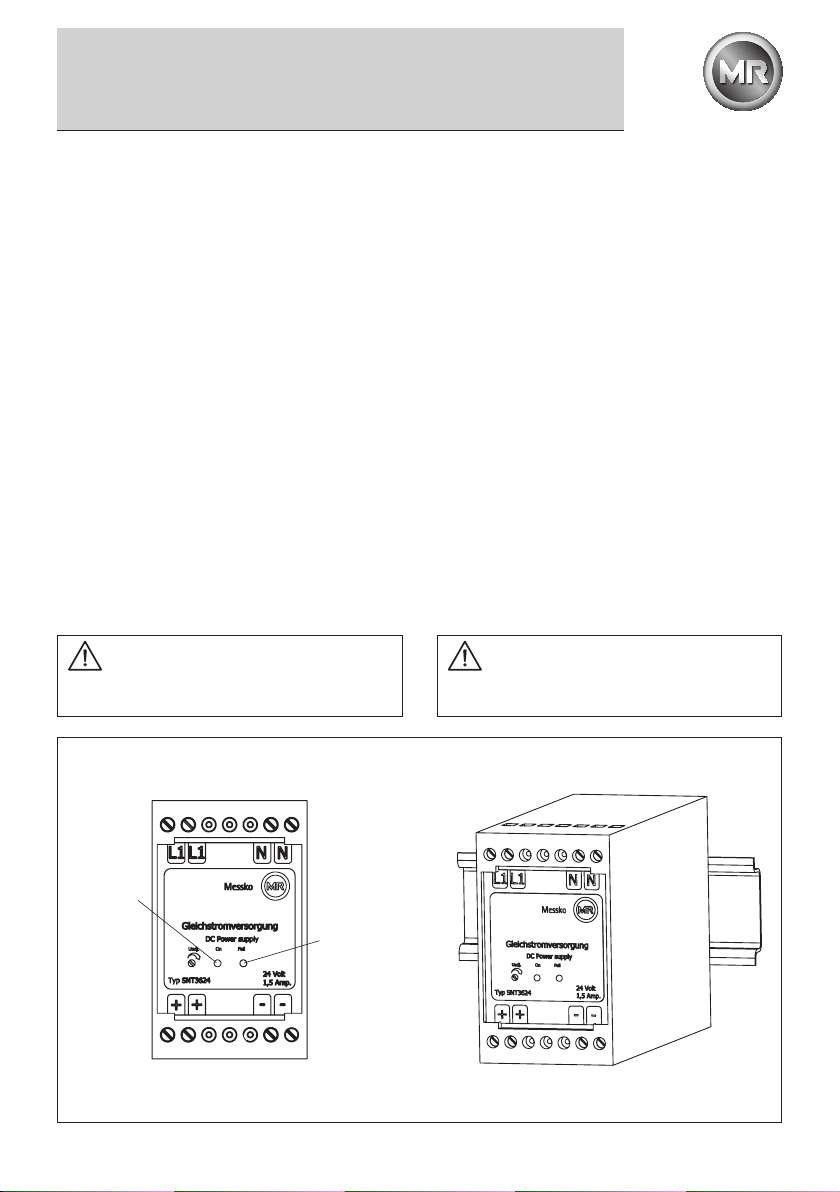
2 Produktbeschreibung
Die Schaltnetzteile sind für einen Eingangsspannungsbereich
von 85-270VAC (0-400Hz) bzw. 110-400VDC ausgelegt.
Ausgangsseitig liefert das Gerät 24VDC.
Das Gerät besitzt folgende Eigenschaften:
• DerAusgangistpotentialfreinachVDE0551.
• Tropentauglich-Gießharzvollverguss.
• Kurzschlussfest,überlast-undleerlaufsicher.
• VerpolungsschutzamAusgang.
• DerEingangkannmit0,8Aträgeabgesichertwerden.
Die grüne LED (siehe Bild 1) signalisiert, dass das Gerät
eingangsseitig ordnungsgemäß angeschlossen wurde und die
Versorgungsspannung anliegt.
Die rote LED (siehe Bild 1) signalisiert eine Störung durch
Kurzschluss,ÜbertemperaturoderÜberlast.NachBeseitigung
der Störung und einer Abkühlzeit kann das Netzteil wieder in
Betrieb genommen werden.
3 Montage
Das Gerät eignet sich zur Montage auf einer 35mm Hutschiene
nach DIN EN 60715 TH35-7,5 bzw. TH35-15 (siehe Bild 1).
2 Product specification
The switching power supply units are designed for an input
voltage range of 85 to 270VAC (0 to 400 Hz) or 110 to 400VDC.
The device supplies 24VDC on the output side.
The device offers the following features:
• Theoutputispotential-freeinaccordancewithVDE0551.
• Canbeusedinthetropics-castresin,fullyencapsulated
• Shortcircuitproof,overloadandnoloadresistant
• Protectedagainstpolereversalontheoutput
• Theinputcanbeprotectedwitha0.8Adelayedfuse.
The green LED (see Fig. 1) signals that the device was con-
nected correctly on the input side and the supply voltage is
available.
The red LED (see Fig. 1) signals a malfunction due to short cir-
cuit, excess temperature or overload. After the correction of
the malfunction and a cooling off period, the power supply
can be put into operation again.
3 Installation
The device is suitble for mounting on a 35-mm rail in accor-
dance with DIN EN 60715 TH35-7,5 or TH35-15 (see Fig. 1).
Grüne LED
Green LED
Rote LED
Red LED
Bild 1/Fig. 1
BA 2084/03/056
4 Elektrischer Anschluss/ Electrical connection
ACHTUNG
Der elektrische Anschluss darf ausschließlich von
qualifiziertem, ausgebildetem Personal, welches in die
entsprechenden Sicherheitsvorschriften des jeweiligen
Landes unterwiesen wurde, durchgeführt werden.
CAUTION
The electrical connection may only be performed by
qualified, trained personnel who have been instructed
in the applicable safety regulations of the particular
country.
4 Elektrischer Anschluss
ACHTUNG
Induktive Verbraucher (Schütze, Motoren, Magnetventile,
etc. die nicht ordnungsgemäß nach den relevanten Richt-
linien entstört sind (Varistoren, RC-Glieder, etc.) können
zur Störung der Netzteilregelung führen.
4 Electrical connection
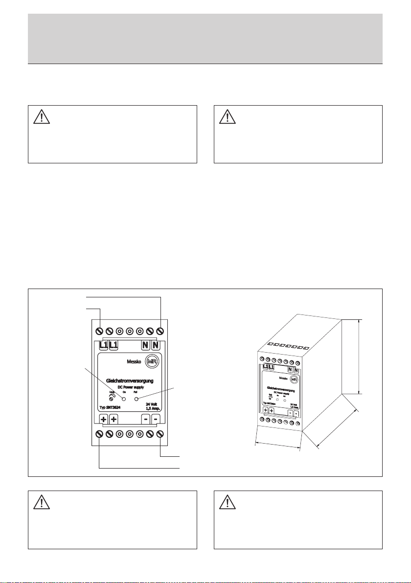
110
75
84
Grüne LED
Green LED
Rote LED
Red LED
Bild 2/Fig. 2
4.1 Eingangsspannung
Eingangsseitigstehenjeweils2KlemmenfürL1(+)undN(-)zum
Anschluss der Eingangsspannung zur Verfügung (siehe Bild 2).
Der Eingang kann mit 0,8A träge abgesichert werden.
4.2 Ausgangsspannung
Ausgangsseitig liefert das Gerät eine Gleichspannung von
24VDC(Klemmen+und-,sieheBild2).DerAusgangistver-
polungssicher, kurzschlussfest, überlast- und leerlaufsicher.
4.1 Input voltage
Ontheinputside,2terminalseachforL1(+)andN(-)are
available for the connection of the input voltage (see Fig. 2).
The input can be protected with a 0.8A delayed fuse.
4.2 Output voltage
On the output side, the device supplies a direct voltage of
24VDC(for+and-terminals,seeFig.2).Theoutputisprotec-
ted against pole reversal and is short circuit proof, and resistant
to overload and no load.
CAUTION
Inductive consumers (contactors, motors, solenoid valves, etc.)
which have not been correctly interference-suppressed in
accordance with relevant guidelines (varistors, RC elements,
etc.) may cause power supply regulation to malfunction.
85 - 270V AC
UIN =
110 - 400V DC
AC/DC-Eingang
AC/DC-Input
DC-Ausgang
DC-Output
-
UOUT= 24V DC
+

BA 2084/03/05 7
5 Technische Daten
Abmessungen: 48mmx75mmx110mm
(BxHxT)
Gewicht: ca. 0,5 kg
Eingangsgrößen
Eingangswechselspannung: 85 - 270V
Schutz gegen Spannungsspitzen: Bis max. 300V
Frequenz: 0 - 400Hz
Eingangsgleichspannung: 110 - 400V
Einschaltstromstoß: 16A
Ausgangsgrößen
Ausgangsspannung: 24VDC ± 1%
Leistungsaufnahme: max. 45VA
Einsatz der Strombegrenzung: ca.1,8A
Restwelligkeit: <25mV
Betriebsdaten
Arbeitstemperatur: -30°Cbis+70°C
Lagertemperaturbereich: -30°Cbis+105°C
Kühlung: natürlicheKonvektion
Sicherheitsdaten
PrüfspannungTrafo: 5kVAC gemäß VDE0551
Hochspannungsfestigung: Eingang/Ausgang 3,75kVAC
nach VDE0806/IEC380
Funkentstörgrad: gemäß VDE0871B und
EN 55022/B
Umgebungsfeuchte: 95% relative Feuchte im
Jahresdurchschnitt,
Betauung möglich,
tropentauglich
Schutzart: IP65 (Gehäuse)
IP20(Klemmen)
nach IEC 60529
Rüttelfestikeit: >30g bei 33Hz in X,Y und Z
nach IEC 68 und DIN 41640
5 Technical Data
Dimensions: 48mmx75mmx110mm
(BxHxD)
Weight: appr. 0.5 kgs
Input data
Input voltage AC: 85 - 270V
Protection against voltage peaks: Up to max. 300V
Frequency: 0 - 400Hz
Input voltage DC: 110 - 400V
Input current peak: 16A
Output data
Output voltage: 24VDC ± 1%
Power consumption: max. 45VA
Start of current limiting: appr. 1.8A
Residual ripple: <25mV
Operating data
Operatingtemperature: -30°Cto+70°C
Storagetemperaturerange: -30°Cto+105°C
Cooling: selfcooling
Safety data
Test voltage transformer: 5kVAC in accordance to
VDE0551
High-voltage resistance: Primary circuit/secondary
circuit 3.75kVAC acc. to
VDE0806/IEC380
Degree of EMI sppression: in accordance to VDE0871B
and EN 55022/B
Ambient humidity: 95% rel. humidity, yearly
average dewing allowed for
use in tropical ambient
Degree of protection: IP65 (housing)
IP20 (terminals)
acc. to IEC 60529
Vibration proof: >30g at33Hz in X,Y and Z
acc. to IEC 68 and
DIN 41640
5 Technische Daten/Technical Data

Messko GmbH
Gewerbegebiet An den Drei Hasen
Messko-Platz 1, 61440 Oberursel, Germany
Phone: +49 6171 6398-0
Fax: +49 6171 6398-98
Email: [email protected]
www.messko.com
Please note:
The data in our publications may dier from
the data of the devices delivered. We reserve
the right to make changes without notice.
BA 2084/03/05 DE-EN – MESSKO® SNT36 –
MS99095601 – 01/14 –
©Messko GmbH 2014
Table of contents
Other MESSKO Power Supply manuals


