MESSRING 8LE-D23 User manual
8LE-D23_BA_E.docm
05.02.2019
1/88
OPERATING INSTRUCTION
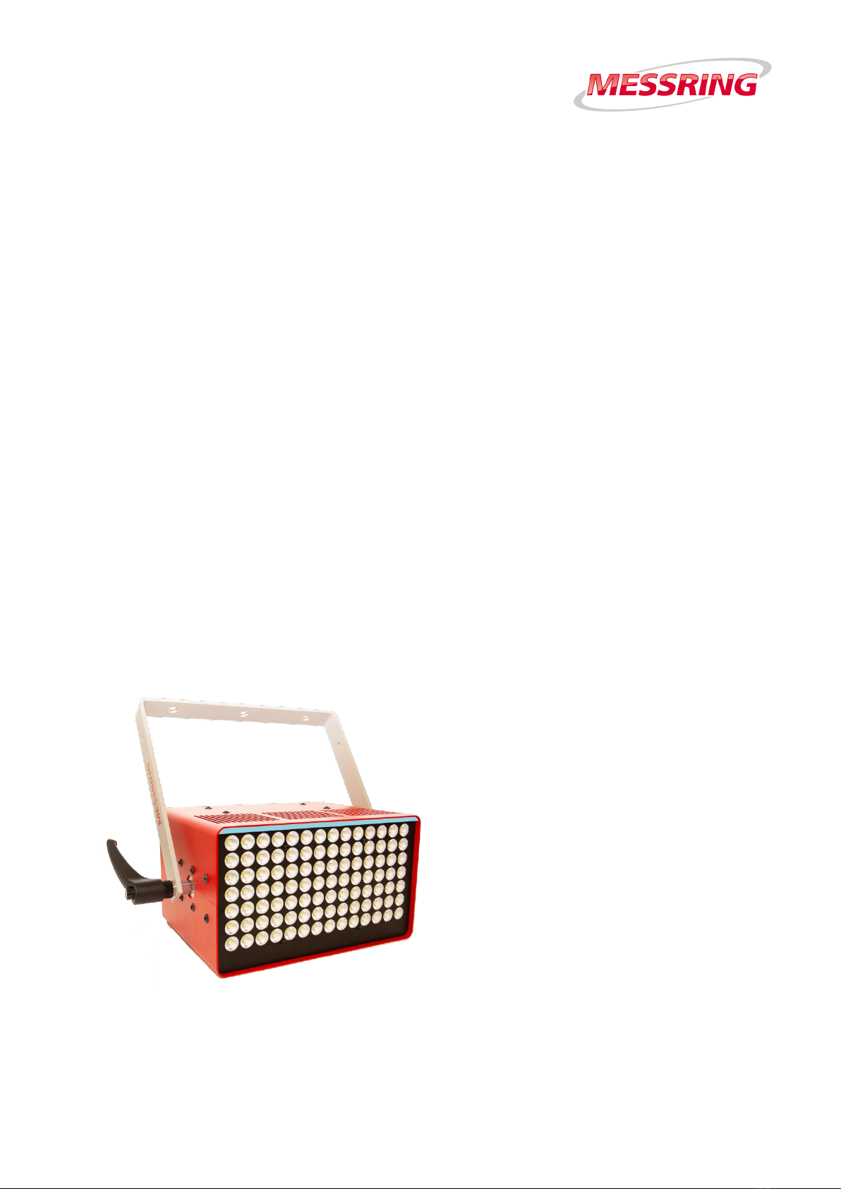
M=LIGHT LED, 1000W 8LE-D23
Contents
Chapter 1 About this operating instruction 2
Chapter 2 Health and Safety 5
Chapter 3 System Description 12
Chapter 4 Setup and Functioning 19
Chapter 5 M=LIGHT Control 43
Chapter 6 Maintenance 71
Chapter 7 Technical data 77
Chapter 8 Handling 79
Chapter 9 EU Declaration of Conformity 87
Chapter 10 Annex 88
Valid from serial number
17-00000
Valid from software version number
2.10.0.59

Property rights according to ISO 16016
About this operating instruction
2/88
05.02.2019
8LE-D23_BA_E.docm
Chapter 1 About this operating instruction
Contents
1.1 Property rights according to ISO 16016 2
1.2 Meaning of this Operating Instruction 2
1.3 Description of Signs and Symbols 3
1.3.1 Warnings 3
1.3.2 Description of More Signs and Symbols 4
1.4 Contact 4
1.1 Property rights according to ISO 16016
The content of this operating instruction is our intellectual property. We appreciate you
understanding, that we CANNOT allow disclosure of this document, either in full or in part, to third
parties, especially our competitors.
1.2 Meaning of this Operating Instruction
The operating instruction is part of your product. Consequently, you must keep this operating
instruction so that it is easily accessible for the operating staff at all times.
When selling or leaving the product to third parties, the operating instruction must be handed over
to the new owner or user. Immediately replace the operating instruction if it is lost or incomplete. In
this event, contact MESSRING GmbH.
Together with this operating instruction, you shall receive documents of third party manufacturers,
if necessary. Also familiarize yourself with these instructions and read the safety instructions and
warnings contained therein.
For your own safety, observe all safety instructions and warnings in chapter 2 of this operating
instruction. Also observe the warnings and safety instructions on the individual components and
activities in the other chapters.

About this operating instruction
Description of Signs and Symbols
8LE-D23_BA_E.docm
05.02.2019
3/88
1.3 Description of Signs and Symbols
1.3.1 Warnings
Depending on the scope of the consequences occurring in case of NON-COMPLIANCE with a
warning, there are four different risk levels. Each risk level is marked with a certain signal word and
a warning sign.
DANGER!
Refers to a dangerous situation which, in case of NON-COMPLIANCE,
will lead to death or severe injuries.
irreversible.
WARNING!
Refers to a dangerous situation which, in case of NON-COMPLIANCE,
may lead to death or severe injuries.
irreversible
CAUTION!
Refers to a dangerous situation which, in case of NON-COMPLIANCE,
may lead to minor or moderately severe injury.
reversible
NOTE!
Damage to property
Contact
About this operating instruction
4/88
05.02.2019
8LE-D23_BA_E.docm
Warning sign
Meaning
Hazard due to electric voltage
Hazard due to optical radiation
1.3.2 Description of More Signs and Symbols
Symbol
Meaning
Step.
Instruction to avoid hazards.
Result of a sequence of actions.
Hint / additional information.
New Test
Element of the CrashSoft user interface or labeling of an operating element.
NOT
Negation
1.4 Contact
MESSRING GmbH
Robert-Stirling-Ring 1
82152 Krailling
Germany
Phone: +49 89 898139-0
Email: service@messring.de

Health and Safety
Contact
8LE-D23_BA_E.docm
05.02.2019
5/88
Chapter 2 Health and Safety
This chapter provides information on dangers which emanate from the product.
The safety instructions and warnings aim to avoid fatal accidents, severe
injuries and damage to property.
Carefully read and observe all instructions in this chapter.
Observe the safety instructions and warnings on the individual
components and activities in the following chapters.
Completely read this operating instruction before beginning with
operation or maintenance of the M=LIGHT LED.
Observe regional, national and company-internal standards, directives
and regulations.
Content
2.1 Target groups 6
2.2 Main Sources of Danger 6
2.3 Purpose 6
2.3.1 Intended Use 6
2.3.2 Warning of Misuse 6
2.4 Staff, Workplaces and Hazard Area 7
2.4.1 Qualification and Level of Knowledge 7
2.4.2 Hazard area 7
2.5 Operator's Duties 8
2.5.1 Information and Instructions 8
2.6 Technical Condition 8
2.6.1 Modifications and Changes 8
2.6.2 Maintenance and Repair 8
2.6.3 Malfunction 8
2.7 Safety during Normal Operation 9
2.7.1 Warnings during Normal Operation 9

Target groups
Health and Safety
6/88
05.02.2019
8LE-D23_BA_E.docm
2.1 Target groups
The following sections of the chapter Health and Safety and Responsibility must be read in any
case:
Target Group
Read paragraphs
Operator of the facility
Chapter 2, completely
Operating staff
Chapter 2, without section 2.6.2
Maintenance staff
Chapter 2, completely
2.2 Main Sources of Danger
The main sources of danger when handling this product are:
I Burns on hot surfaces.
I Hazards due to electric voltage.
I Remaining under suspended loads.
I Eye injuries due to optical radiation.
I Danger to life for persons with active implants (e.g. cardiac pacemaker).
2.3 Purpose
2.3.1 Intended Use
The M=LIGHT LED is used for stationary lighting of fast processes recorded with a camera in
indoor areas, e.g.:
I Vehicle and sled tests in crash test facilities.
I Airbag ignition and unfolding.
I Tests with partial car bodies or vehicle interior equipment.
2.3.2 Warning of Misuse
Do NOT use M=LIGHT LED in outdoor areas.
Do NOT use M=LIGHT LED as work lighting for permanent work spaces.
Do NOT use M=LIGHT LED as on-board lighting.
Do NOT use M=LIGHT LED in the drip area under film pit covers.
Any use NOT described in section 2.3.1 is NOT as intended and consequently NOT PERMITTED.

Health and Safety
Staff, Workplaces and Hazard Area
8LE-D23_BA_E.docm
05.02.2019
7/88
2.4 Staff, Workplaces and Hazard Area
2.4.1 Qualification and Level of Knowledge
The M=LIGHT LED may be operated only by appropriately trained staff. The staff must carefully
read the operating instruction for the M=LIGHT LED beforehand and be familiar with the mode of
operation.
Maintenance and repair work on the M=LIGHT LED may only be carried out by qualified staff
specially trained for this purpose.
First read the Health and Safety chapter of the crash test facility completely before working
at the crash test facility.
First read the operating instruction of the M=LIGHT LED carefully before operating the
M=LIGHT LED for the first time.
Do NOT carry out any work for which you have NOT been trained.
The staff must know and comply with the applicable regulations for occupational health and safety
and for accident prevention.
WARNING!
Severe injuries or death from reduced responsiveness through alcohol
and other drugs or medications
Even minor quantities of alcohol and drugs impair concentration and the ability
to react. This may lead to very severe injuries or even death.
Do NOT work with the M=LIGHT LED if your concentration and
ability to react are impaired by drugs or alcohol.
2.4.2 Hazard area
For persons with active implants, the hazard area of 1 m around the M=LIGHT LED applies.

Operator's Duties
Health and Safety
8/88
05.02.2019
8LE-D23_BA_E.docm
2.5 Operator's Duties
2.5.1 Information and Instructions
Store the operating instructions within reach for operating and maintenance staff.
Carefully read the operating instruction before using the product.
Ensure that all persons are familiar with and comply with the current occupational health
and safety regulations.
2.6 Technical Condition
2.6.1 Modifications and Changes
DO NOT make any unauthorized changes to the product.
2.6.2 Maintenance and Repair
Strictly comply with all test and maintenance intervals.
Have maintenance work carried out only by appropriately trained maintenance staff.
Have only work which is described in this operating instruction carried out.
Have failures remedied immediately.
2.6.3 Malfunction
DO NOT operate the M=LIGHT LED if there is a defect.
DO NOT operate the M=LIGHT LED if a defect is suspected.
Inform MESSRING Service in the event of a defect (Section 1.4, Page 4).
Health and Safety
Safety during Normal Operation
8LE-D23_BA_E.docm
05.02.2019
9/88
2.7 Safety during Normal Operation
2.7.1 Warnings during Normal Operation
DANGER!
Severe injuries or death may be caused by electric shock from electric
charge inside the housing.
Immediately after disconnection, the contacts of the mains plug may still carry
voltage for a short period.
Do NOT touch the contacts of the mains plug directly after switch-off.
DANGER!
Severe injuries or death for persons with active implants
The magnetic field of the M=LIGHT LED may interfere with the function of
implants, e.g. cardiac pacemakers, if the safety distance specified for the
implant is not complied with.
Persons with active implants must keep a distance of at least 1 m to the
activated M=LIGHT LED.
DANGER!
Severe injuries or death due to dangerous electrical shock or burns due to
melting power cord
Unsuitable power cords can cause the power cord to overheat, resulting in
serious injury, death, burns, and dangerous voltage surges on the melting power
cord.
Use only the hot appliances power cord supplied by MESSRING with the
M=LIGHT LED.
DO NOT replace hot appliance power cords with other power cords.
DANGER!
Severe injuries or death may be caused by electric shock from electric
voltage
Work on components that have NOT been disconnected and are under
dangerous electric voltage will cause severe injuries (e.g. burns, paralysis,
cardiac arrest), including death.
Only have work carried out by qualified experts.
Use only power cords supplied by MESSRING with the M=LIGHT LED.
Observe the safety rules for switching-off and securing before working at
power lines and devices.

Safety during Normal Operation
Health and Safety
10/88
05.02.2019
8LE-D23_BA_E.docm
CAUTION!
Eye injuries due to optical radiation
Radiation with light from the M=LIGHT LED may lead to damage of the retina
and cornea of the eyes.
Keep sufficient safety distance to activated M=LIGHT LEDs.
Wear safety goggles when working on switched-on M=LIGHT LED
(e.g. Infield, Terminator Orange UV-400 / Art. no.: 9380 420).
Do NOT stay within radiation range of the lamp longer than required.
Do NOT directly look into the beam of light.
Do NOT use M=LIGHT LED as lighting for work stations.
CAUTION!
Burns at hot surfaces
Risk of burning on the housing of the M=LIGHT LED at temperatures of up to
100 °C.
Allow M=LIGHT LED to cool down first before touching it.
Risk of burning on the shaft of the M=LIGHT LED suspension after prolonged
operating time.
Do NOT touch the shaft of the suspension during operation or shortly
after switching off the M=LIGHT LED.
NOTE!
Damage and breakdown of the M=LIGHT LED
Overheating of the M=LIGHT LED due to insufficient ventilation.
Do NOT cover the ventilation slots.
Do NOT position the M=LIGHT LED directly on the housing.
DO NOT install the M=LIGHT LED in the exhaust air flow of additional
M=LIGHT LEDs.
NOTE!
Damage and breakdown of individual LEDs due to deposits of grease
or sweat.
Destruction of individual LEDs due to overheated grease or sweat residues.
Do NOT touch the LED array.
If required, rub the LEDs with a dry, clean cotton cloth.
Do NOT use cleaning agents.

Health and Safety
Safety during Normal Operation
8LE-D23_BA_E.docm
05.02.2019
11/88
NOTE!
Damage and malfunction of the LED array due to dripping liquids, as
well as water or oil during operation of the M=LIGHT LED in film pits.
Destruction of the LED array due to short circuit.
Make sure NO liquids can drip on the M=LIGHT LED.

Safety during Normal Operation
System Description
12/88
05.02.2019
8LE-D23_BA_E.docm
Chapter 3 System Description
Contents
3.1 Scope of Delivery 13
3.2 Specification 13
3.2.1 Special Properties and Performance Data 14
3.3 Main components of M=LIGHT LED 14
3.4 Accessories 15
3.4.1 M=LIGHT connection set USB 15
3.4.2 M=LIGHT installation set for stationary installation 17
3.4.3 Web IO Digital for TCP/IP 18

System Description
Scope of Delivery
8LE-D23_BA_E.docm
05.02.2019
13/88
3.1 Scope of Delivery
Quantity
Component
1
M=LIGHT LED, 1000 W
Option
M=LIGHT Connection set USB (8LE-D22-2)
Option
M=LIGHT Installation set (8LE-D24-2)
3.2 Specification
M=LIGHT LED for continuous or pulsed operation.
The M=LIGHT LED is made up of 98 LEDs and can be used in continuous or pulsed operation. In
pulsed operation, the M=LIGHT LED is synchronized with the high-speed camera and twice as
much light output can be achieved as in continuous mode. The M=LIGHT LED can optionally be
operated manually or via the CAN-bus with the help of the software. In pulsed operation, it is
possible to eliminate backlight effects due to control of separate M=LIGHT LED groups. For the
elimination of backlight effects, only one camera synchronized with one M=LIGHT LED group is
switched on (Figure 1).
Figure 1: Synchronization in pulsed operation
Pos.:
Description
1
Camera 1 switched on
2
M=LIGHT LED group 1 switched on
3
M=LIGHT LED group 2 switched off
4
Camera 2 switched off
5
Camera 1 switched off
6
M=LIGHT LED group 1 switched off
7
M=LIGHT LED group 2 switched on
8
Camera 2 switched on

Main components of M=LIGHT LED
System Description
14/88
05.02.2019
8LE-D23_BA_E.docm
3.2.1 Special Properties and Performance Data
I NO warm-up time required; the M=LIGHT LED is ready for operation directly after being switched
on.
I Test object is NOT overheated by radiation of heat.
I Can be synchronized with the Sync signal from a camera, a SYNC generator or M=Sync.
I CAN-bus-controlled.
I Non-flickering and dimmable.
I Stable aluminum housing.
I Customized lighting angles.
I Service life of the LEDs: more than 50,000 hours.
I Delay between Sync input and light flash: approx. 10 µs.
3.3 Main components of M=LIGHT LED
I LED array with status indication.
I Aluminum housing.
I Support bracket for one- and two-point attachment.
I CAN-bus connections.
I M=LIGHT control software for control of the M=Light LED via CAN-bus.
I CAN-bus interface for control of the CAN-bus via USB connection or network connection
(optional).

System Description
Accessories
8LE-D23_BA_E.docm
05.02.2019
15/88
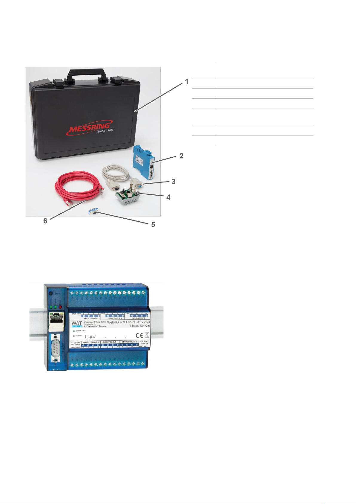
3.4 Accessories
3.4.1 M=LIGHT connection set USB
M=LIGHT connection kit for mobile connection of M=LIGHT LED, camera system and PC.
Figure 2: Connection M=LIGHT, camera and PC (schema)
Pos.:
Description
Cable NOT included in the scope of delivery
Cable included in the scope of delivery
1
USB-to-CAN Compact Interface Adapter
2
Cable length up to 90 m
3
M=LIGHT LED BUS Splitter mobile
4
12-24 V DC
5
Cable length up to 70 m

Accessories
System Description
16/88
05.02.2019
8LE-D23_BA_E.docm
Pos.:
Description
1
M=LIGHT LED BUS Splitter mobile
2
USB-to-CAN Compact Interface
Adapter
3
Power supply unit, power supply
4
Ethernet cable, software
5
Case
Figure 3: Scope of delivery for M=LIGHT connection set USB for mobile installation (8LE-D22-2)

System Description
Accessories
8LE-D23_BA_E.docm
05.02.2019
17/88
3.4.2 M=LIGHT installation set for stationary installation
Pos.:
Description
Cable NOT included in the scope of delivery
Cable included in the scope of delivery
1
12-24 V DC
2
Cable length up to 70 m
3
12-24 V DC
4
Cable length up to 90 m
5
CAN@net II Interface Adapter
6
Sub-D extension 9-pin included in the scope of delivery.
7
BUS terminator
8
Cable length up to 90 m
9
M=LIGHT LED BUS splitter for stationary installation
Figure 4: M=LIGHT installation set for stationary installation (schema)
Accessories
System Description
18/88
05.02.2019
8LE-D23_BA_E.docm
Pos.:
Description
1
Case
2
CAN@net II Interface Adapter
3
Sub-D extension 9-pin
4
M=LIGHT LED BUS splitter for
stationary installation
5
BUS terminator
6
Ethernet cable
Figure 5: Scope of delivery of M=LIGHT installation set for stationary installation (8LE-D24-2).
3.4.3 Web IO Digital for TCP/IP
Figure 6: 9.1 Web IO Digital for TCP/IP
The Web IO is an interface between the PLC of a test rig or crash test facility and the M=LIGHT
Control. The Web IO is used to enable an external PLC to send signals to the M=LIGHT Control or
to receive them from the M=LIGHT Control.

Setup and Functioning
Accessories
8LE-D23_BA_E.docm
05.02.2019
19/88
Chapter 4 Setup and Functioning
Contents
4.1 LED Array 20
4.1.1 Status display and fan speed with the LED matrix activated 20
4.1.2 Status display and fan speed with the LED matrix deactivated 21
4.2 Lighting angles 22
4.3 Rear Side of the Housing 24
4.3.1 Connecting / Disconnecting Voltage Supply 24
4.3.2 Establishing Signal Connections 26
4.3.3 Contact Assignment of CAN-Bus Connections 27
4.4 Support bracket 28
4.4.1 Changing the handle position of the attachment screws 29
4.5 M=LIGHT connection set USB 30
4.5.1 M=LIGHT LED BUS Splitter mobile 30
4.5.2 Connections M=LIGHT LED BUS Splitter mobile 30
4.5.3 USB-to-CAN Compact Interface Adapter 31
4.6 M=LIGHT LED BUS splitter stationary 33
4.6.1 CAN@net II 35
4.6.2 Bus terminator 37
4.6.3 Sub-D extension 9-pin 37
4.7 Web IO installation and programming 38
4.7.1 Activate Web IO for M=LIGHT Control 38
4.7.2 Adjusting the Web IO Digital 39
4.7.3 Select Web IO operating mode and light group 42
LED Array
Setup and Functioning
20/88
05.02.2019
8LE-D23_BA_E.docm
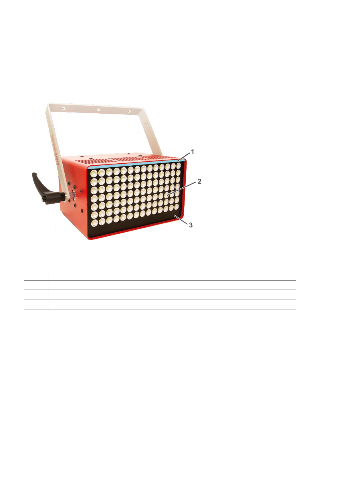
4.1 LED Array
The status display in the LED array shows the most important operating states of the M=LIGHT
LED.
Figure 7: LED array with status indication
Pos.:
Description
1
Status indication in the LED array
2
LED matrix
3
Front plate
4.1.1 Status display and fan speed with the LED matrix activated
The status display is switched off immediately after switching on the LED matrix.
The fan comes on when the LED array reaches a temperature of 26 °C.
Table of contents
Popular Lighting Equipment manuals by other brands

Equinox Systems
Equinox Systems SpectraPix Lithium Batten user manual

Lena Lighting
Lena Lighting UV-C STERILON SQUARE HEPA 2 144W PP Installation instruction

Lighting Technologies
Lighting Technologies ADV/K Series manual

Natec
Natec ALFAMA user manual

Renkforce
Renkforce 1170825 operating instructions

PLUSLITE
PLUSLITE FRESNEL PL200 User instructions

Doug Fleenor Design
Doug Fleenor Design PRESET 8 Installation and operation manual

Profoto
Profoto ProDaylight 800 Air user guide

Code 3
Code 3 XTP Series Installation and operation instructions

TPL VISION
TPL VISION SQUARE LIGHT RGB user guide

Lightolier
Lightolier Soli 48023ALU specification

Thorn
Thorn TROPHY installation instructions


