ZG Lighting Australia Pty Ltd.
www.thornlighting.com.au
ZG Lighting (NZ) Limited
www.thornlighting.com.nz 10/13
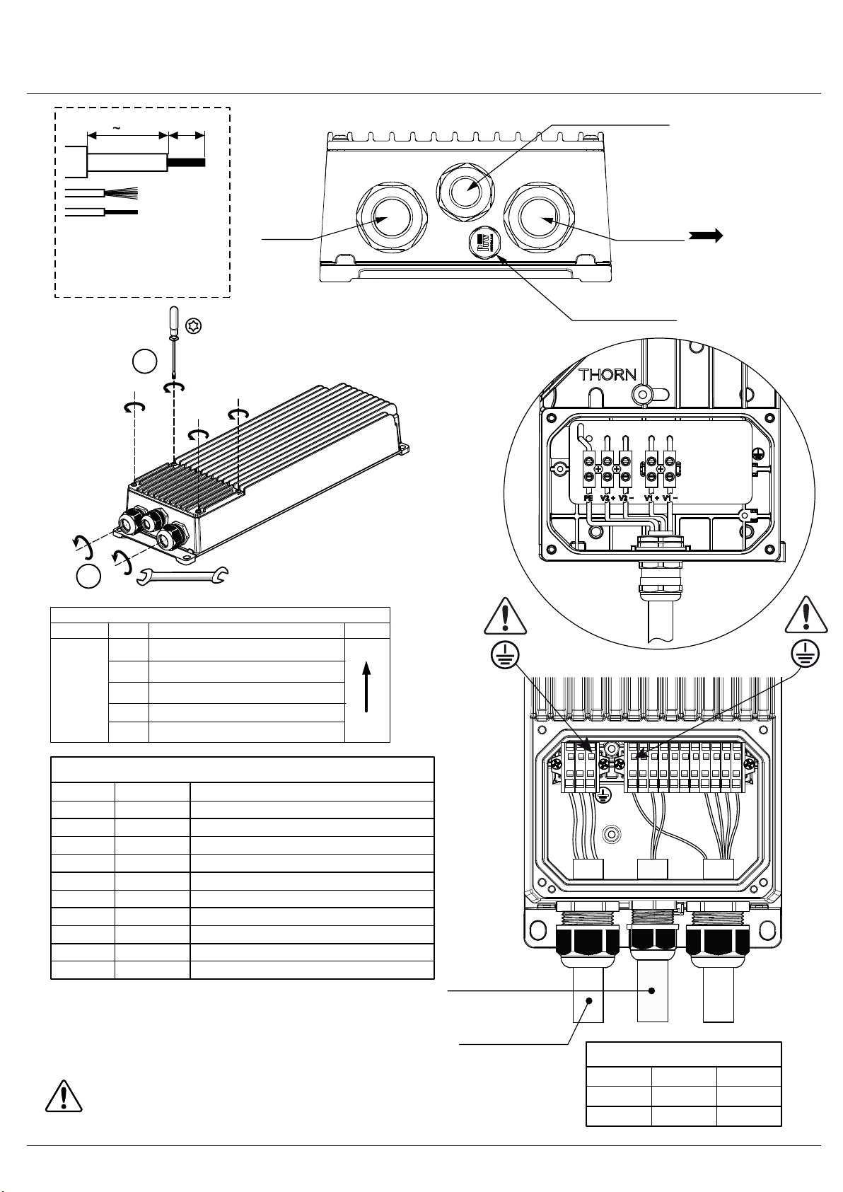
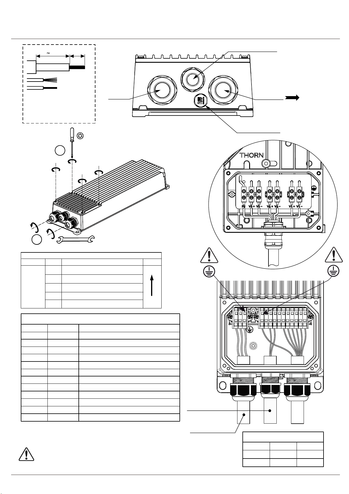
TROPHY GB IP66 468L / ELECTRICAL CONNECTION
8-9 mm
PINOUT
TROPHY GB Description
L AC INPUT
N
PE
AC INPUT
PROTECTIVE EARTH
PE PE FOR LED MODULE
DA+
CABLE GLAND
ØMinTYPE ØMax
6.3 mmM20 11.3 mm
10 mmM25 16.3 mm
The wiring should be strictly followed by the marking label instruction,
otherwise the product could be damaged or the functions could be affected.
Each set of + or - are not potential identical, cross connection is prohibited.
INPUT
M25
OUTPUT
M25
Ventilation Valve
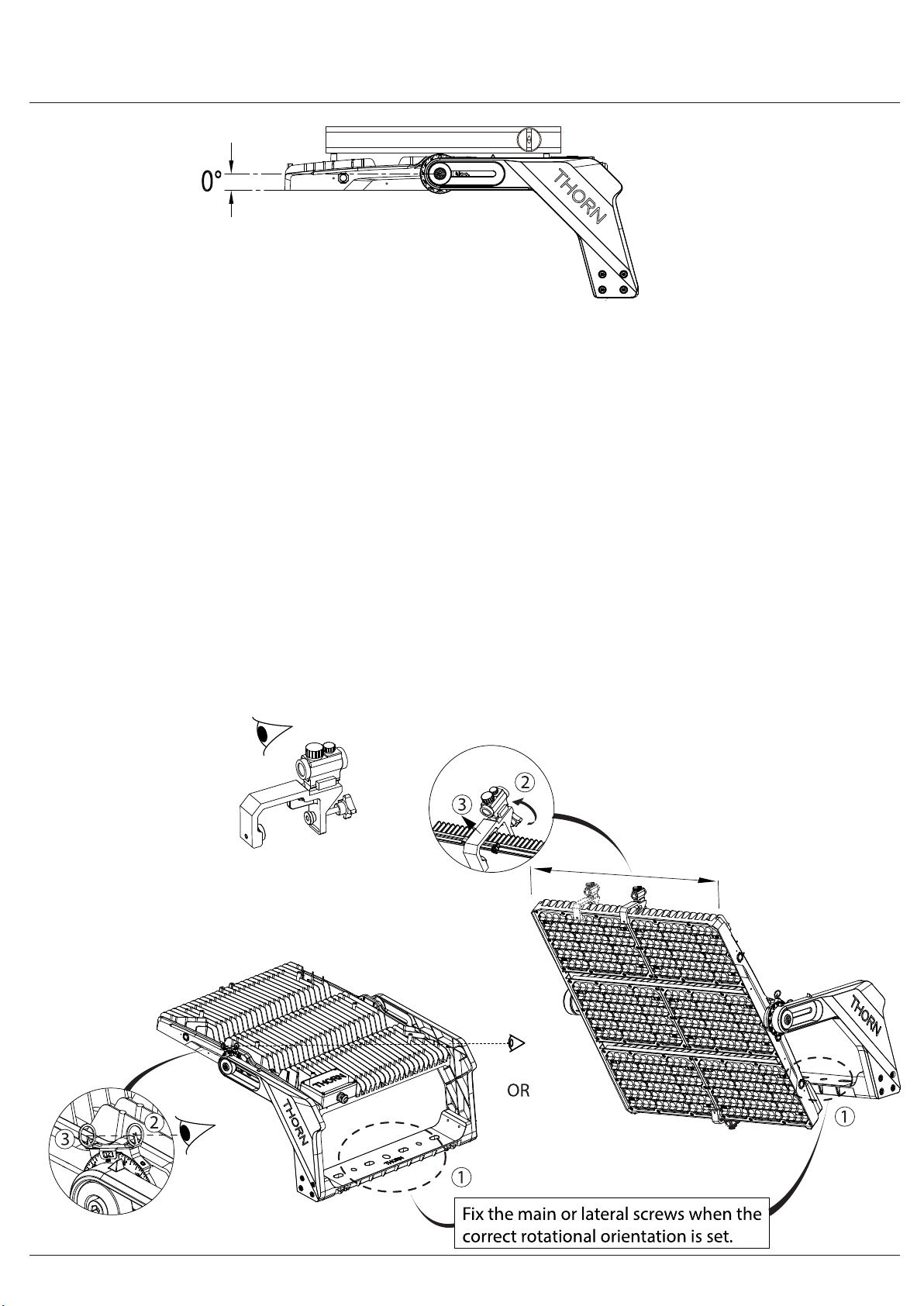
Floodlight
L N
PE PE NC DA+ DA- V3+ V3- V2+ V2- V1+ V1-NTC
Recommended :
H07RNF 3G1.5 mm²
50
Ø min = 1,0 mm²
Ø typ = 1,5 mm²
Ø max = 2,5 mm²
OK
V3-
V2+
V2-
V1+
OUTPUT CHANNEL 3- (BOT BRICK)
OUTPUT CHANNEL 2+ (MID BRICK)
OUTPUT CHANNEL 2- (MID BRICK)
OUTPUT CHANNEL 1+ (TOP BRICK)
OUTPUT CHANNEL 1- (TOP BRICK)V1-
OUTPUT CHANNEL 3+ (BOT BRICK)V3+
DA- DALI INPUT DA-
DALI INPUT DA+
DALI
M20
Recommended :
H07RNF 2G1.5 mm²
V3-
V2+
V2-
V1+
V1-
V3+
30
T20
2
1
30
T20
2
1
SIGNALLING LED INDICATIONS ON THE GEAR BOX
1
2
5
3
4
PERIOD PULSES FAULT DESCRIPTION PRIORITY
The encoded
faults are
based on
pulses
emitted every
4 seconds
Maximum
Minimum
One or more CCR module enabled by config are not
communicating with logic board
Firmware version of one or more CCR module is not
compatible with logic board firmware version
One or more CCR’s output is short-circuited
Load failure on one or more CCR’s output
Thermal derating active (output current reduction)