Met One BC 1060 User manual

BC 1060-9800 Rev B Page 1
Met One Instruments, Inc.
1600 NW Washington Blvd.
Grants Pass, OR 97526
Telephone: (541) 471-7111
Facsimile: (541) 471-7116
www.metone.com
BC 1060 Operation Manual - ©
Copyright 2018 Met One Instruments, Inc. All Rights Reserved worldwide. No part of this
publication may be reproduced, transmitted, transcribed, stored in a retrieval system, or translated into any other language in any
form without the express written permission of Met One Instruments, Inc.
BC
1060
B
LACK
C
ARBON
M
ONITOR
O
PERATION
M
ANUAL
BC
1060-9800,
R
EV
B

Page 2 BC 1060-9800 REV B

BC 1060-9800 REV B Page 3
Table of Contents
1 INTRODUCTION 5
1.1 About This Manual 5
1.2 Technical Service 5
1.3 BC 1060 – Two Wavelength Black Carbon Monitor 6
1.4 Safety Warnings 6
1.5 BC 1060 Instrument Specifications 7
2 SITE SELECTION AND POSITIONING CRITERIA 8
3 SETUP & DEPLOYMENT 8
3.1 Unpacking 8
3.2 Electrical Service 9
3.3 Shelter & Mounting Options 9
3.4 Sample Inlet Configurations 9
3.5 Assembling the BC 1060 9
3.6 Installing the Comet Cloud Modem 12
3.7 Filter Tape Installation, Loading, and Filter Material Notes 13
3.7.1 Installing Filter Tape on Initial Setup 13
3.7.2 Replacing Used Filter Tape 14
3.7.3 Verifying Remaining Filter Tape 15
3.8 Starting and Stopping Sample Operation 15
3.8.1 Entering the Setup Menu 15
3.8.2 Starting Initial Sample Operations 16
3.8.3 Stopping and Resuming Sample Operations 17
4 USER INTERFACE AND MENU SYSTEM 17
4.1 The User Interface Keypad and Display Functions 17
4.2 Main Sampling Screens 18
4.3 Menu Hierarchy and Navigation 19
4.4 Start or Stop Sample 20
4.5 Load Tape 20
4.6 View Alarm Log 20
4.7 Copy to USB Drive 20
4.8 The SETUP MENU 21
4.8.1 The CLOCK Setup Screen 21
4.8.2 The SAMPLE Setup Screen 21
4.8.3 The SERIAL PORT Setup Screen 22
4.8.4 The MEMORY Setup Screen – Clearing the Memory 22
4.8.5 The PASSWORD Setup Screen 22
4.8.6 The DIGITAL SENSOR Setup Screen 23
4.9 The CALIBRATE MENU 23
4.9.1 The CALIBRATE AT Screen 23
4.9.2 The CALIBRATE BP Screen 23
4.9.3 The CALIBRATE FLOW Screens 23
4.9.4 The CALIBRATE DILUTION Screens 24
4.9.5 The CALIBRATE AUDIT Screens 25
4.10 The TEST MENU 25

Page 4 BC 1060-9800 REV B
4.10.1 The SELF TEST Screen 25
4.10.2 The TAPE TEST Screen 26
4.10.3 The LEAK TEST Screen 26
4.10.4 The DIGITAL LINK Screen 26
4.11 The ADVANCED Menu 27
4.12 The ABOUT Screen 27
5 BC 1060 AIRFLOW SYSTEM 28
5.1 Airflow Control System Descriptions 29
5.2 Dilution Flow System Description 29
6 MAINTENANCE AND TROUBLESHOOTING 30
6.1 BC 1060 Error & Alarm Event Descriptions 30
6.2 Basic Problem Causes/Solutions Table 33
6.3 Suggested Periodic Maintenance Intervals 34
6.4 Temperature, Pressure, and Flow Audits and Calibrations 35
6.4.1 Ambient Temperature Calibration 35
6.4.2 Barometric Pressure Calibration 35
6.4.3 Flow Sensor Calibration 36
6.4.4 Dilution Flow Sensor Calibration 37
6.4.5 Temperature, Pressure, and Flow Audits 39
6.4.6 The CALIBRATE AUDIT Menu – Performing Optical Span Tests 39
6.5 Flow System Leak Checks 41
6.6 Debris Filter Changes 41
6.7 Inlet and Cyclone Cleaning 42
6.8 Internal Fuse 43
6.9 Factory Service Interval 44
7 DATA RETRIEVAL AND COMMUNICATIONS 44
7.1 Collecting BC 1060 Data Using a USB Flash Drive 44
7.2 BC 1060 Cloud Data 45
7.3 BC 1060 Data Outputs and Data Examples 45
7.4 Downloading Data Using Terminal Utility Programs 48
7.4.1 User Communication 48
7.4.2 Computer Communication 49
7.5 Flash Firmware Upgrades 51
8 ACCESSORIES AND PARTS 52
9 PRINCIPLE OF OPERATION 54
9.1 Mass Calculation 54
9.2 Instrument Calibration 56
9.3 Filter Media and Loading Effects 57

BC 1060-9800 REV B Page 5
1 INTRODUCTION
1.1 About This Manual
This document is organized with the most important information toward the front of the manual. All
users should read and understand the sections on setup, operation, and field audits. Toward the
back are sections that provide in-depth information on subjects such as diagnostics and
accessories. These sections should be consulted as needed.
This manual is periodically revised for maximum accuracy and to incorporate new features or
updates. User feedback is welcome. An electronic version of this manual is available upon request.
1.2 Technical Service
Should support still be required after consulting the printed documentation, contact one of the
expert Met One Instruments, Inc. Technical Service representatives during normal business hours
of 7:00 a.m. to 4:00 p.m. Pacific Time, Monday through Friday. In addition, technical information
and service bulletins are often posted on our website. Please contact us and obtain a Return
Authorization (RA) number before sending any equipment back to the factory. This allows us to
track and schedule service work and to expedite customer service.
Contact
Information:
Tel: + 541 471 7111
Fax: + 541 471 7115
Web: http:/www.metone.com
Email:
service@metone.com
Address:
Met One Instruments, Inc.
1600 Washington Blvd
Grants Pass, Oregon
97526 U.S.A.
Please have the instrument serial number available when contacting the manufacturer. On most
models manufactured by Met One Instruments, it will be located on a silver product label on the
unit, and also printed on the calibration certificate. The serial number will begin with a letter and be
followed by a unique four or five digit number such as U15915.

Page 6 BC 1060-9800 REV B
1.3 BC 1060 – Two Wavelength Black Carbon Monitor
The Met One Instruments, Inc. model BC 1060 Portable Carbon Monitor is a two-wavelength black
carbon monitor. It automatically measures and records optical transmission across filter media onto
which particulate matter has been deposited. Two industry standard wavelengths, 880 nm and 370
nm are used to determine the concentration of black carbon “BC” and “UVPM” (UV light absorbing
PM), respectively.
Figure 1-1 The BC 1060
Ambient air is drawn into the instrument at a controlled flow rate, generally though a size-selective
PM
2.5
or PM
1
fractionator. The sampled air is subsequently drawn through a heated inlet section
and then through special glass fiber filter tape, capturing ambient particulate matter. Optical
transmission at both wavelengths is measured through the filter tape allowing BC mass
concentrations to be calculated at each wavelength. The filter tape will advance when sufficient
particulate matter has been deposited on the tape to cause the attenuation of the selected channel
to exceed a factory recommended level or a user-selected value.
1.4 Safety Warnings
Optical Warnings: The BC 1060 monitor employs an LED light source in the near UV (370 nm)
and one the near IR (880 nm). This light is outside the range of normal human vision and could
present a potential invisible ocular exposure hazard. The UV light source is a 15 mW LED, emitting
at 370 nm. The near infrared source is a 7 mW IR LED emitting at 880 nm. Appropriate
precautions should be employed.
A protective housing with this warning symbol fully encapsulates the light
sources and optics system during normal operation. Whenever the optical
module is disassembled for service, the power cord must be disconnected in
order to prevent accidental exposure to UV and IR radiation.

BC 1060-9800 REV B Page 7
Electrical Warnings: The BC 1060 is a 12 Volt DC powered system, and there are no hazardous
live voltages located anywhere inside the instrument. It is equipped with an external desktop power
supply module with a 100-240 VAC 50/60 Hz input range, and a 12 VDC, 8.5 A output. The BC
1060 instrument is housed in a weather-proof case for deployment outdoors.
NOTE: Use ONLY Factory Power Supply. NO SUBSTITUTIONS!
Thermal Warnings: The instrument contains a 12 Volt 40 Watt internal heater, in the form of two
large, gold colored power resistors and a circulation fan located inside the electronics chassis.
These resistors are usually hot and should not be touched while the instrument is powered on, or
within several minutes after being powered off. The inlet heater tube located near the top and
inside the instrument may also be warm to the touch while operating and for several minutes after
powering off.
1.5 BC 1060 Instrument Specifications
PARAMETER SPECIFICATION
Measurement Principle:
Optical Absorption Wavelength
880 nm BC
370 nm UVPM
Measurement Range: 0.01 µg/m
3
to 100 µg/m
3
BC
Data Display Resolution 0.1 ng/m
3
LLD: ≤50 ng/m
3
with 1 minute sample time, ≤8 ng/m
3
with 1 hour sample time
Measurement Interval: 1, 5, 10, 15, 30, or 60 minutes
Sample Rate: 2 LPM
Filter Tape: Proprietary treated glass fiber
Operating Temperature: 0 to +40°C
Inlet Heater: 13 W (setpoints from 25 to 40 °C)
Ambient Sensor: 80866-1 ambient temperature sensor with solar shield included.
Sensor Input: Support for digital Wind Speed and Wind Direction inputs
Internal Data Storage: 4MB internal memory.
Data Download: One USB Flash Drive Port, USB Serial, RS-232 serial, Comet Cloud Modem
User Interface: Menu-driven interface with 4x20 character OLED display and dynamic keypad.
Mounting Options: Bench top or free standing with optional stand. A weatherproof shelter is not
required.
Unit Weight: Approximately 35 lbs. (18 kg)
Unit Dimensions: Height: 12” (30.5 cm) Width: 14” (35.6 cm) Depth: 14.5” (36.8 cm).
Input Power: 100 to 240VAC, 102 W
Specifications may be subject to change without notice. See BC 1060 datasheet for latest published specs.

Page 8 BC 1060-9800 REV B
2 SITE SELECTION AND POSITIONING CRITERIA
There are no special installation requirements for the BC 1060. It should simply be positioned in
the area containing the air to be sampled based on local monitoring needs.
3 SETUP & DEPLOYMENT
The BC 1060 is designed for easy setup and simple configuration for most applications. This
section describes the basic assembly, setup, and start-up of the instrument.
3.1 Unpacking
Unpack the carbon monitor and accessories and compare them to the packing list to make sure all
items are present.
Any damages to the equipment during shipping are the responsibility of the carrier. If any damage
to the shipment is noticed before unpacking, a claim must be filed with the commercial carrier
immediately. Follow any special unpacking instructions provided by the carrier as all items are
carefully removed from the containers and each component inspected. It is recommended to
document and photograph all damaged packages and items before, during, and after unpacking
them. Contact Met One Instruments (see Section 1.2 of this manual) to arrange for any
replacement items needed.
The instrument is supplied with one of each of the following standard accessories:
•TSP Inlet (part number 9441)
•PM2.5 Sharp Cut Cyclone (part number SCC 112)
•Power Supply Assembly (part number 82536) – includes housing, power supply, and US
power cord
•RS-232 Serial Communications Cable (part number 82459)
•USB Cable, A-B male (part number 500784)
•Span Check Membrane (part number 83011)
•Ambient Temperature Sensor with Cable (part number 80866-1)
•Solar Radiation Shield for Ambient Temperature Sensor (part number 820471)
•Filter Tape, one roll (part number 460211)
•Operation manual (part number BC 1060-9800)
•Comet Software CD (part number 80248)
•Assorted tubing and fittings
Optional Accessories may include:
•Mounting Stand (part number BCX-901)
•All In One Weather Sensor (AIO 2)
•Met Station One Weather Station (MSO)
•Comet Cloud Modem 2

BC 1060-9800 REV B Page 9
3.2 Electrical Service
The BC 1060 uses an external DC power supply which can be supplied with 100 - 240 VAC, 50 or
60 Hz input power. The sampler is rated at 70 Watts maximum continuous power with the sample
pump running. There are no hazardous live voltages located anywhere inside the instrument. The
power supply provides a 12 VDC, 8.5 A output. It is not weatherproof if removed from its protective
housing so the power supply should never be deployed outdoors without its case.
NOTE: Use ONLY Factory Power Supply. NO SUBSTITUTIONS!
The sample site needs to be equipped with AC power and a standard weatherproof outdoor
electrical outlet.
For critical applications, where possible sample invalidations due to power failures are
unacceptable, the sampler should be equipped with an uninterruptable power supply (UPS). The
supply must be rated for the electrical load and must be appropriately configured for an outdoor
application. Consult a qualified electrical contractor.
3.3 Shelter & Mounting Options
The BC 1060 is a weatherproof monitor designed to be mounted on a stand and then deployed in
the outdoors without the need for a shelter or other housing. However, if it is desired, it may also
be installed in an indoor location such as a walk-in shelter, a trailer or mobile lab, a mini outdoor
shelter, or inside of a permanent structure.
Benchtop Mounting: The BC 1060 may be installed on a table-top. Make sure the mounting
surface is level, and that the instrument is secured so that it won’t “walk” due to vibration. Always
leave adequate clearance at the back of the unit for access to the data port, power, ambient probe
connections and sampling lines.
3.4 Sample Inlet Configurations
The BC 1060 is designed to operate with an in-line PM
2.5
or PM
1
fractionator through flexible tubing
connected to the back of the instrument. The fractionators (sharp cut cyclones or SCC) are
designed to sample at 2 LPM.
The TSP inlet mounts atop the dilution adapter. The adapter is coupled directly to the inlet of the
SCC which is mounted on top of the 82977 support tube. The flexible sample tubing connects
onto the bottom of the support tube and is routed to the BC 1060 sample inlet on the rear of the
monitor. It connects using a push-to-connect fitting. See Figure 3-2.
3.5 Assembling the BC 1060
The BC 1060 is designed for easy setup and deployment. This allows it to be used for either
permanent long-term sampling at a fixed site or for portable audit sampling for temporary
applications.
Page 10 BC 1060-9800 REV B
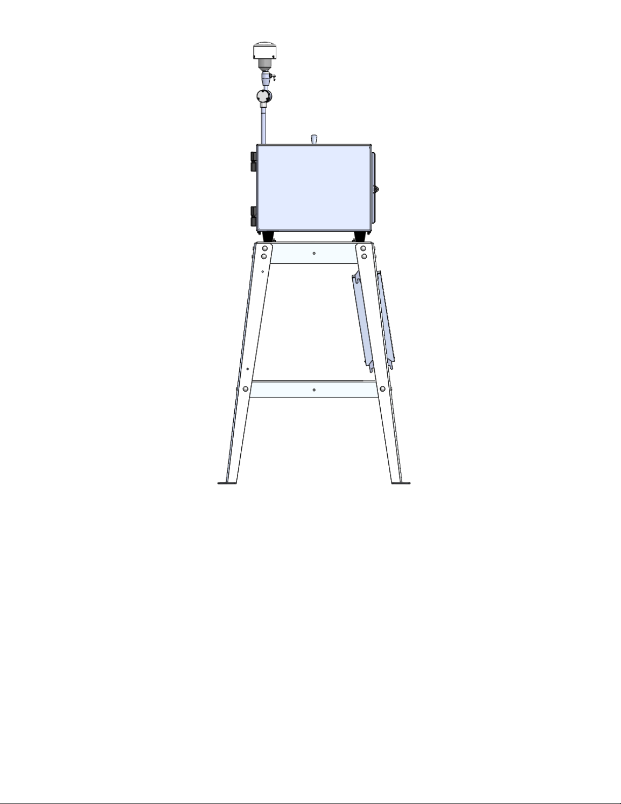
Figure 3-1 The BC 1060 Shown with Optional BCX-901 Stand
The following describes the standard method of setting up the BC 1060. If using the optional
mounting stand or sample inlet extension kit, refer to the associated manuals for those items for
additional instructions. Refer to Figure 3-2 and Figure 3-3.
1. Connect the TSP Inlet to the dilution adapter: Slide the TSP inlet onto the top of the
dilution adapter. Be certain the TSP inlet is fully seated onto the dilution adapter.
2. Connect the dilution adapter to the SCC: Slide the dilution adapter onto the inlet of the
SCC. Be certain the dilution adapter is fully seated onto the SCC.
3. Mount the SCC to the Support Tube. The support tube inlet should be inserted into the
outlet of the sharp cut cyclone. Be certain the inlet tube is fully seated within the cyclone.
4. Mount the Inlet Support Tube: Locate the inlet support tube mount on the back of the BC
1060 housing. Lightly pinch the upper and lower grips together and slide the tube through
both mounting holes. At the desired height, release the grips and the tube should be held
securely in place.
BC 1060-9800 REV B Page 11
5. Connect the Tubing: The dilution adapter will have a length of small flexible tubing
installed. This should be routed through the support tube mount to the appropriate fitting on
the back of the BC 1060 and inserted into the push-to-connect fitting. The sample inlet
tubing should be installed onto the bottom of the support tube and then into the sample port
on the back of the BC 1060. Both connections are made using push-to-connect fittings.
6. Connect the Ambient Temperature Sensor: The BC 1060 comes with an ambient
temperature sensor. The sensor should be mounted on the rear wall of the BC 1060 using
the two threaded studs located in the upper left corner. Remove the captive retaining
knobs, place the sensor bracket over the mounting studs and screw the knobs back onto
the rear of the monitor. Once mounted, connect the sensor signal cable to the three-pin
connector located beneath the sensor on the rear of the monitor.
7. Connect the Power Supply: Connect the power supply to the four-pin power connector on
the back panel of the BC 1060. The power supply has a universal AC voltage input. The
included US-type modular power cord can be changed to another type if needed.
The BC 1060 monitor is now ready to have power applied and begin the initial configuration
sequence. Plug in the AC power cable and follow the on-screen prompts. See Section 3.8.
Filter tape installation is described in Section 3.7.
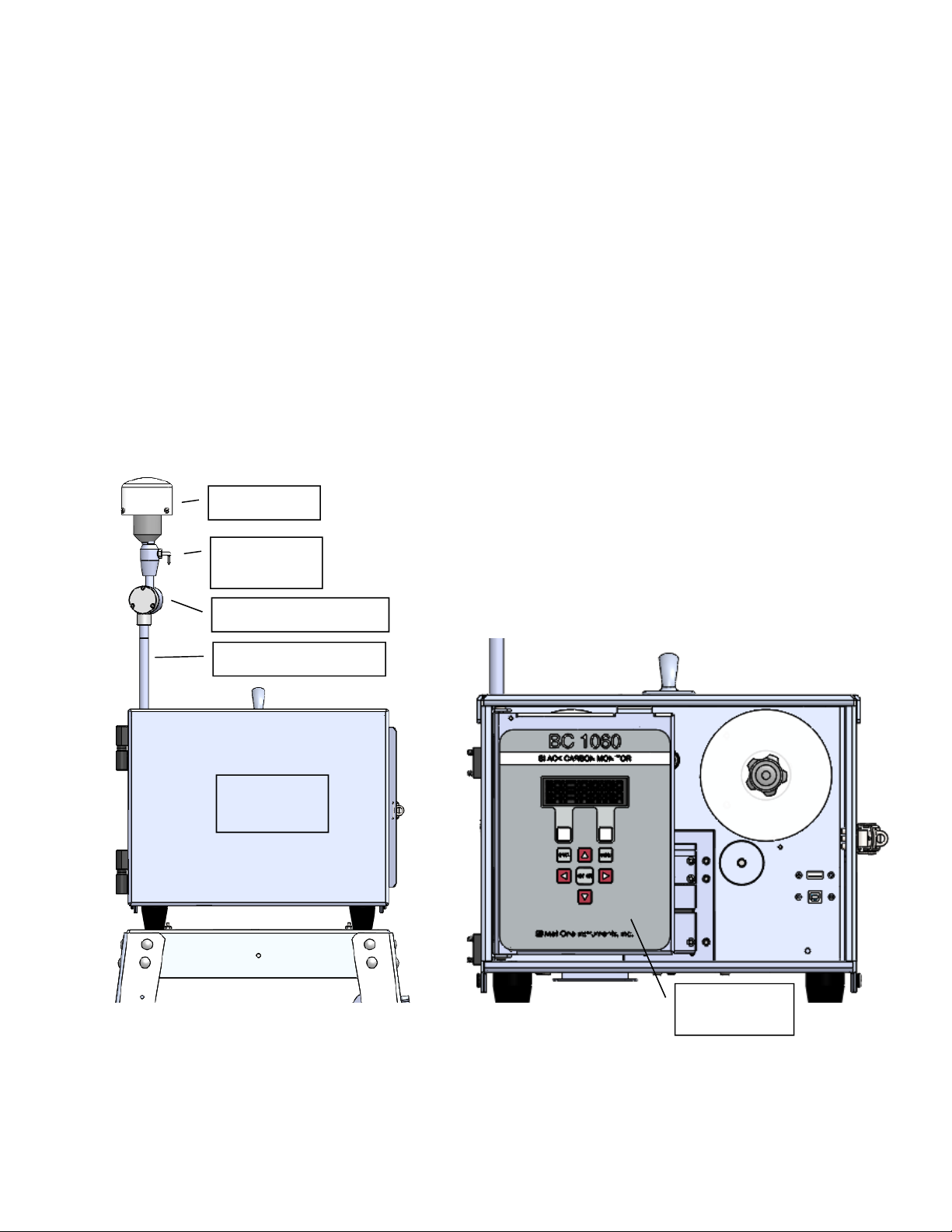
Figure 3-2 BC 1060 Front View
TSP Inlet
Dilution
Adapter
Sharp Cut Cyclone
Inlet Support Tube
Enclosure
Door
Display and
Keypad
Page 12 BC 1060-9800 REV B
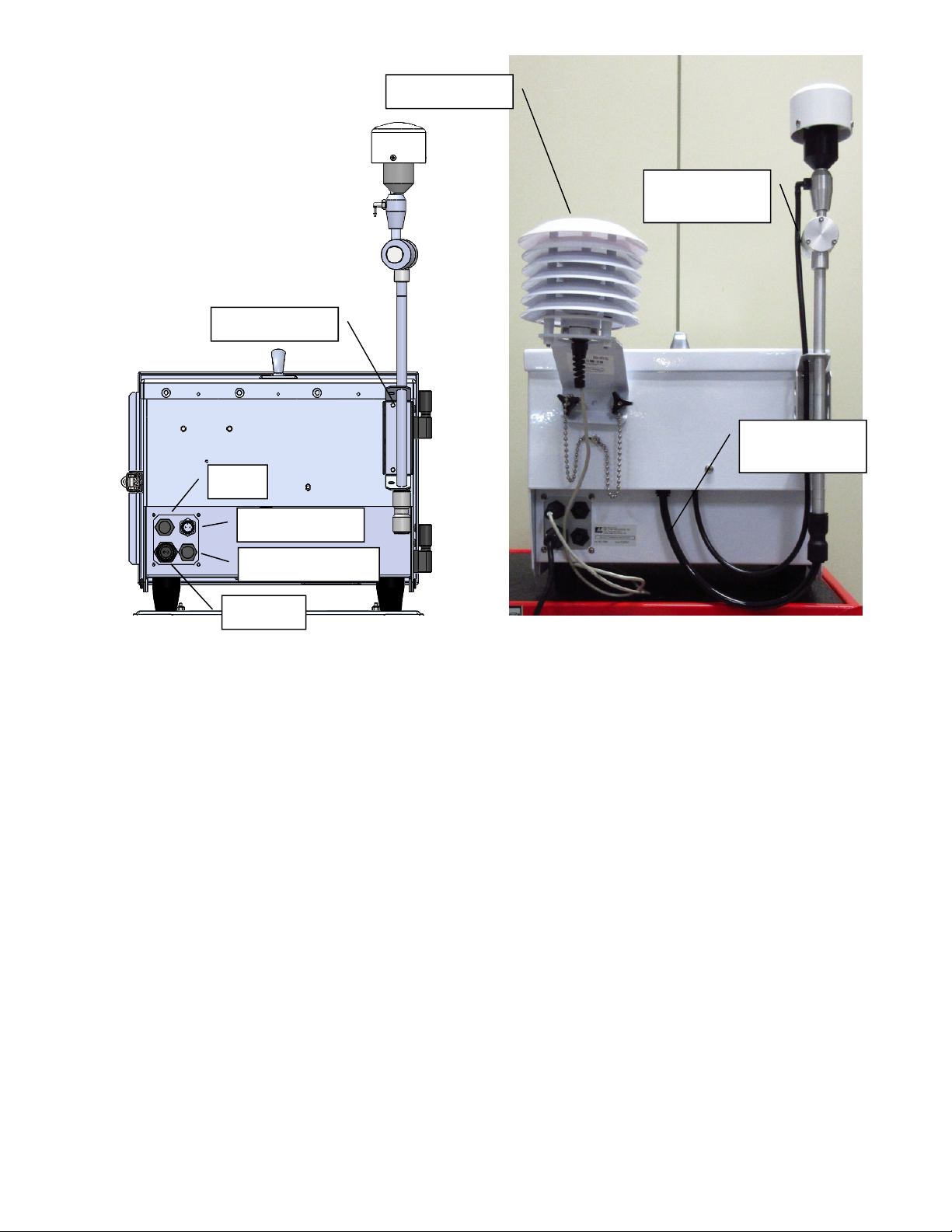
Figure 3-3 BC 1060 Rear Panel Connections
3.6 Installing the Comet Cloud Modem
The Comet Cloud Modem is an optional accessory that allows data collected by the BC 1060 to be
automatically pushed to the cloud. Data can then be charted and viewed on a web page from any
computer or mobile device with internet access. A cable connects the CCS Modem 2 to the BC
1060 Serial Comm connector (Figure 3-3). See CCS Modem 2 manual for more details.
AT
Power
Serial Comm
Digital Sensor
AT Sensor
Dilution
Tubing
Sample
Tubing
Inlet Mount

BC 1060-9800 REV B Page 13
3.7 Filter Tape Installation, Loading, and Filter Material Notes
The BC 1060 carbon monitor uses treated glass fiber filter tape rolls, available from Met One
Instruments under part number 460211. It is essential that this tape be used in the BC 1060 in
order to maintain proper instrument calibration and reproducibility. Since the filter tape advance
frequency depends upon filter-loading, the frequency with which the tape needs to be replaced is
variable. A roll of filter tape is expected to last anywhere from 2 to 12 months, depending on the
sampling conditions, tape load level, load channel and dilution settings selected.
Note: The BC 1060 tape transport system runs the filter tape from left to right. Notice that this
places the clean roll on the left side of the monitor. This is the opposite of the configuration used in
the Met One Instruments BAM-series monitors.
Warning: The filter tape is rolled with the checker pattern on the outside of the roll, and the softer
side on the inside. If the new roll is installed backwards on the supply reel, then the backing
material will be on top inside the measurement module, resulting in improper measurement. The
instrument cannot identify this incorrect condition.
3.7.1 Installing Filter Tape on Initial Setup
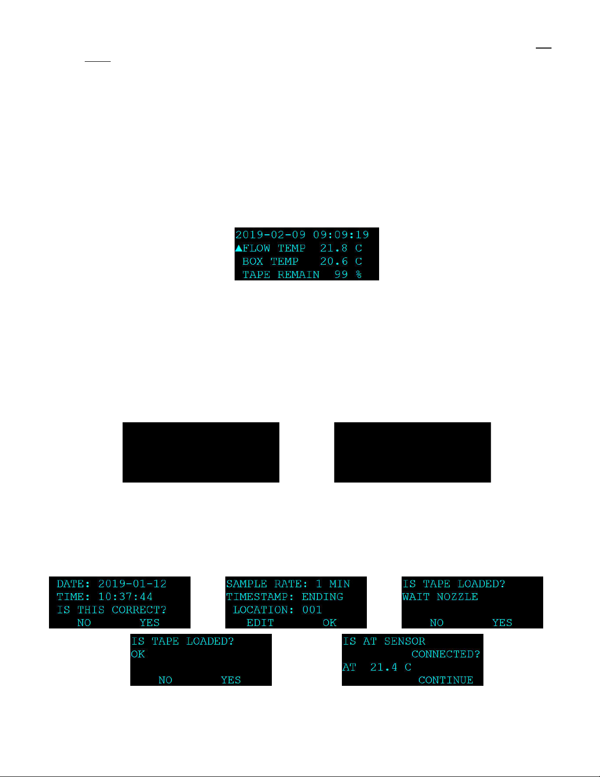
1. Apply power to turn the instrument ON.
2. Select SETUP when prompted (see Figure 3-8).
3. Advance past the first two setup screens (see Section 3.8.1).
4. Press the NO softkey on the “IS TAPE LOADED” screen.
5. Select YES to ARE YOU LOADING A NEW ROLL OF TAPE. The sequence will advance to
the tape counter reset screen (see Figure 3-4).
Figure 3-4 BC 1060 New Tape Loading Sequence Screens
6. Select YES to reset the tape counter to 100% TAPE REMAINING and advance to the LOAD
TAPE screen (see Figure 3-4).
7. Select OPEN to open the measurement module, if not already open.
8. Loosen the two tape reel knobs and remove the reel covers.
9. Install the new filter tape roll onto the left (supply) reel, with the tape coming off the left side
of the roll. Route the tape exactly as shown in Figure 3-5. It should go under the metal idler,
through the slot in the measurement module, under the encoder wheel, and then up to the
take-up reel on the right side of the instrument. Fasten the loose end of the tape to the left
edge of an empty core tube installed on the take-up reel, with cellophane tape. Make sure
that the softer side is UP and the textured side is DOWN.
10.Align the filter tape and take up the slack by turning the left (supply) reel.
11.Press the MOVE softkey. Verify that the tape spools correctly. Advance at least one turn of
filter tape over the take-up core.
12.Use the ESC key to return to the main menu.

Page 14 BC 1060-9800 REV B
Figure 3-5 BC 1060 Filter Tape Routing
3.7.2 Replacing Used Filter Tape
1. From the Main Menu, select LOAD TAPE.
2. Select YES to ARE YOU LOADING A NEW ROLL OF TAPE. The sequence will advance to
the tape counter reset screen (see Figure 3-6).
Figure 3-6 BC 1060 Replacement Tape Loading Sequence Screens
3. If installing a new full roll of tape, select YES to reset the tape counter to 100% TAPE
REMAINING and advance to the LOAD TAPE screen (see Figure 3-6).
If it is not desired to reset the counter to 100%, press the NO softkey to keep the current
remaining percentage. This may be necessary, for example, if the tape has been removed
for maintenance and then the same partial roll is being reinstalled.
4. Select OPEN to open the measurement module, if not already open.
5. Loosen the two tape reel knobs and remove the reel covers.
6. Remove the used tape and cores from the tape spools.
7. Install the new filter tape roll onto the left (supply) reel, with the tape coming off the left side
of the roll. Route the tape exactly as shown in Figure 3-5. It should go under the metal idler,
through the slot in the measurement module, under the encoder wheel, and then up to the
Encoder
Take-Up Reel
(used filter tape)
Rotates Clockwise
Supply Reel
(clean filter
tape)
Passive Idler
Measurement
Module
BC 1060-9800 REV B Page 15
take-up reel on the right side of the instrument. Fasten the loose end of the tape to the left
edge of an empty core tube installed on the take-up reel, with cellophane tape. Make sure
that the softer side is UP and the textured side is DOWN.
8. Align the filter tape and take up the slack by turning the left (supply) reel.
9. Press the MOVE softkey. Verify that the tape spools correctly. Advance at least one turn of
filter tape over the take-up core.
10.Use the ESC key to return to the main menu and then resume normal operations.
3.7.3 Verifying Remaining Filter Tape
1. From the main sampling screen, scroll to the bottom of the display with the ▼(down arrow)
key.
2. The remaining percentage of tape will be displayed as the last line (see Figure 3-7).
Figure 3-7 BC 1060 Tape Remaining
3. Scroll to the top of the main sampling screen with the ▲key for the default main sampling
screen view.
3.8 Starting and Stopping Sample Operation
When 12 VDC power is applied to the rear power connector, the BC 1060 will boot up and display
a splash screen identifying the instrument. After about three seconds, the Welcome screen is
displayed and the options to immediately begin sampling or to enter the setup menus are
presented.
Figure 3-8 BC 1060 Boot Sequence Screens
3.8.1 Entering the Setup Menu
Press the SETUP softkey to verify the required hardware connections and instrument configuration
settings. Pressing the NO or EDIT softkeys on any of the SETUP menu screens will provide
options for correcting or updating the items being displayed.
Figure 3-9 BC 1060 Setup Menu Screens
BC 1060
WWW.METONE.COM
WELCOME TO BC 1060
ARE YOU READY TO
START?
START NOW SETUP
Page 16 BC 1060-9800 REV B
Waiting on the TAPE LOADED? screen will force the BC 1060 to perform a tape test operation. If
the tape must be loaded, pressing the ESC key once it is installed will return to the SETUP
sequence. If the YES softkey is pressed on the TAPE LOADED? screen, the monitor will skip the
test and advance to the final screen to verify the AT senor is connected. Once complete, the BC
1060 will begin sampling as described in Section 3.8.2.
3.8.2 Starting Initial Sample Operations
Pressing the START NOW softkey will place
the BC 1060 into the sampling mode. A timer
will display indicating that sampling will begin
soon. The timer starts at 60 seconds and
counts down in one second intervals.
Figure 3-10 BC 1060 Boot Sequence Screens
The BC 1060 will automatically start sampling when the timer reaches zero. To start sampling
immediately, press the START softkey option. To cancel the startup sequence and enter the
Sampling Screen, press the STOP softkey option. After 30 minutes of inactivity, the unit will
automatically resume sampling.
If the START softkey is pressed, the monitor will advance to a fresh spot of filter tape, turn on the
pump, and display WAIT TOP-OF-MINUTE in the status field. Then the status field will change to
SAMPLING… It will take two full minutes before BC concentrations will appear if Sample Time is
set to 1 minute. If Sample Time is set for a longer period, the BC 1060 will display concentrations
after 1 full sample period.
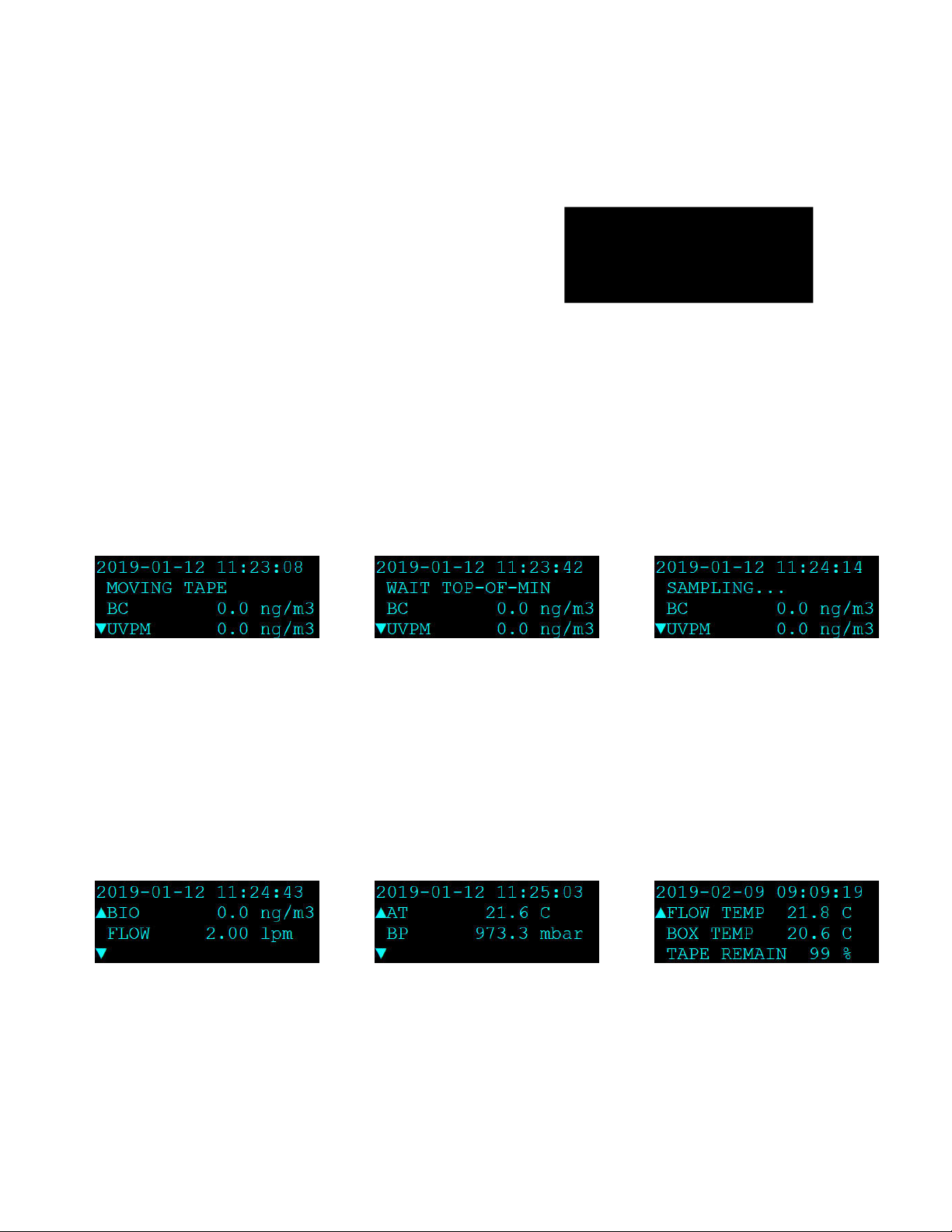
Figure 3-11 BC 1060 Startup Screens
The ▼icon on the left side of the screen indicates that the down arrow on the keypad can be used
to view the additional measurement channels. Press the down and up arrows, when indicated, to
cycle through the additional screens. The down arrow will navigate to the next screen and the up
arrow will return to the previous screen. Additional parameters available in the main screen are the
BIO measurement, total sample flow rate, dilution flow rate, ambient temperature, barometric
pressure, (Wind Speed, Wind Direction and RH, if digital sensor is enabled) sample flow path
temperature at the filter tape, internal temperature of the BC 1060 enclosure, and filter tape
remaining percentage. See samples of these screens in Figure 3-12. Note that the optional digital
sensor screens are not shown in these examples.
Figure 3-12 BC 1060 Additional Main Menu Screens
After powering up and starting sampling, the BC 1060 takes 1 – 3 hours to warm up and equilibrate
before optimal measurement stability is achieved.
The BC 1060 carbon monitor is factory configured with an array of default settings that are
appropriate for most sampling requirements. The operator may consider changing some of these
settings depending on specific requirements. See Section 4 for details about the user interface and
the instrument settings.
SAMPLE WILL BEGIN
IN 42 SECONDS...
STOP START
BC 1060-9800 REV B Page 17
3.8.3 Stopping and Resuming Sample Operations
To stop sampling, press either the ESC or MENU button while on the main screen. This will exit
the main screen and enter the main menu. Place the flashing cursor next to the STOP SAMPLE
option at the top of the menu and press the ENTER key. The BC 1060 will ask the user to confirm
if the sample should be stopped. If confirmed, the BC 1060 will stop running and return to the
main menu.
To resume sampling after the unit has been stopped for any reason, return to the main menu. The
top option of the menu will now read START SAMPLE. Place the cursor on this option and press
the ENTER key. The BC 1060 will ask the user to confirm if the sample should be started. If
confirmed, the BC 1060 will begin the startup sequence (see Section 3.8.2) and return to the
Sampling Screen.
Figure 3-13 BC 1060 Stop/Start Sample Screens
4 USER INTERFACE and MENU SYSTEM
This section describes the BC 1060 user interface system, and describes the functions of the main
menu options, including how to view data and errors.
Figure 4-1 BC 1060 User Interface and Display
4.1 The User Interface Keypad and Display Functions
The BC 1060 user interface consists of a 4x20 OLED display and a dynamic keypad. The two
white keys under the display are called “softkeys” or “hot keys”. These are dynamic keys which
change in response to a menu option displayed directly above them on the bottom row of the
display. The function of these keys depends on which menu is shown on the display.
Page 18 BC 1060-9800 REV B
The four arrow (cursor) keys are used to scroll up, down, left, and right, to navigate in the menu
system, and to select items or change fields on the screen. The arrow keys are also often used to
change parameters or increment/decrement values in the menu system.
The MENU key is used to enter the main menu. The ESC key is used to escape or exit out of a
screen or menu. The ENTER key enters parameters in a selected field or selects an item in a list.
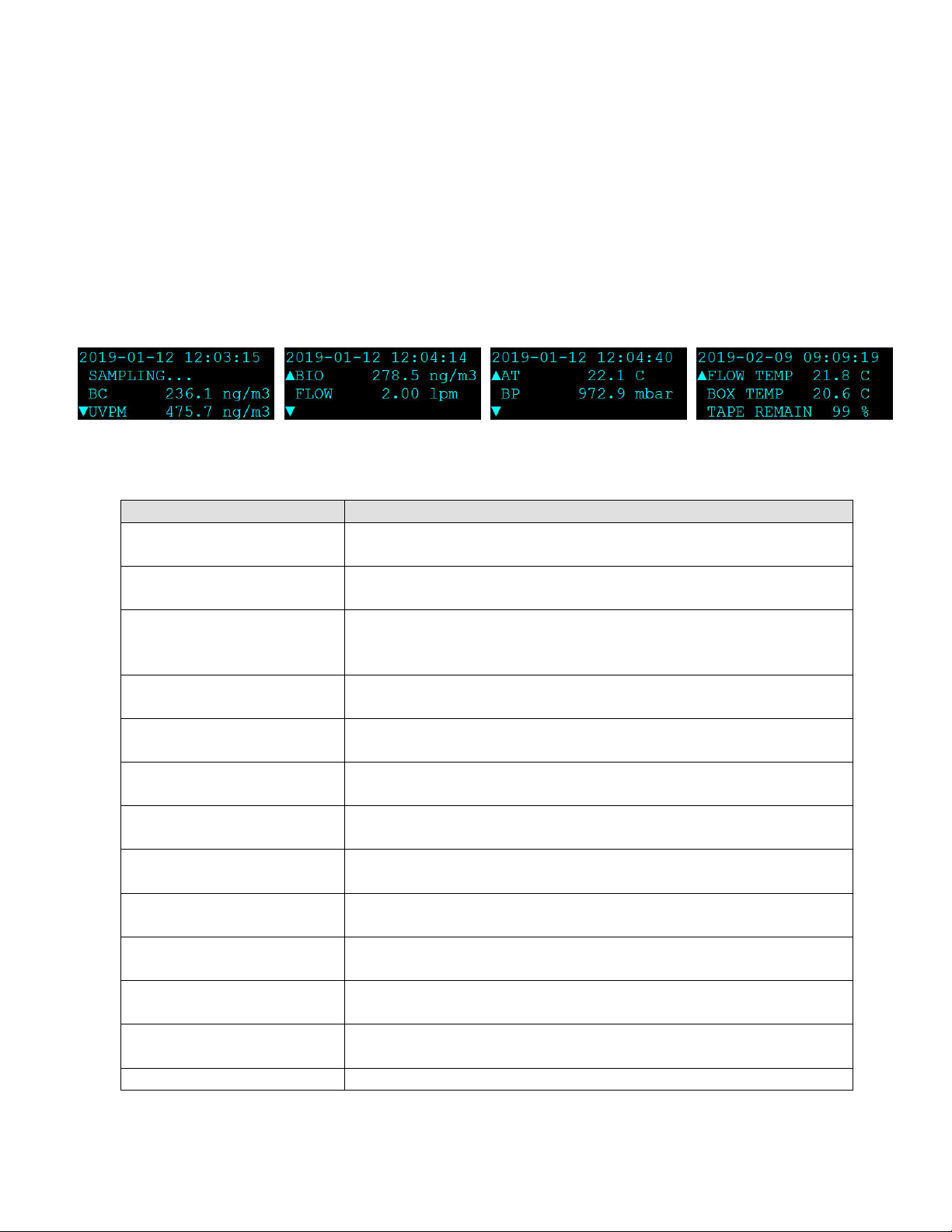
4.2 Main Sampling Screens
The BC 1060 main sampling/operation screens are shown in Figure 4-2. The current date and
time are always fixed at the top line of the display in these screens. The up/down arrow keys can
be used to scroll to additional viewable parameters. Note: Digital Sensor WS/WD/RH reports not
shown.
Figure 4-2 Main Sampling Screen order
The definitions of the fields shown in Figure 4-2 are as follows:
Parameter
Description
BC Sample period average of the black carbon concentration.
Nanograms per cubic meter.
UVPM Sample period average of the UV particulate concentration.
Nanograms per cubic meter.
BIO
Calculated concentration value: UVPM – BC. May be an
indicator of organic aerosol (Biomass) content. Nanograms
per cubic meter.
FLOW Sample period average of the actual sample flow rate
(through the sample filter)
. L
iters per minute
.
DILUTION Sample period average of the actual dilution flow rate.
L
iters per minute
.
AT Sample period average of the real-time ambient
temperature
.
Celsius.
BP Sample period average of the real-time ambient barometric
pressure
.
millibar.
WS Sample period average of the wind speed as reported by
the digital sensor, if present and enabled. Meters/second
WD Sample period average of the wind direction as reported by
the digital sensor, if present and enabled. Degrees
RH Sample period average of the relative humidity as reported
by the digital sensor, if present and enabled. Percent.
FLOW TEMP Sample period average of the temperature of the sample
air f
low measured just after the
filter tape
.
Celsius.
BOX TEMP Sample period average of the temperature of the inside of
the
BC 1060 enclosure
.
Celsius.
TAPE REMAIN
Estimated filter tape remaining. Percent.
Table 4-1 Main Display Parameter Descriptions

BC 1060-9800 REV B Page 19
4.3 Menu Hierarchy and Navigation
The BC 1060 menu structure is outlined in the following table:
Main Menu Sub Menu Options Overview
Power-On Start-up Menu
Section 3.8
No sub menu Guided Set-Up to help ensure instrument is ready to start sampling
Sampling Screen
Section 4.2
No sub menu Displays date, time, operational mode, carbon concentrations, flow
rates, ambient conditions and internal temperatures.
Start/Stop Sample
Section 4.4
No sub menu Start and stop sampling operations
Load Tape
Section 4.5
No sub menu Install the filter tape, verify tape movement, View filter tape remaining
percentage, and reset tape counter
View Alarm Log
Section 4.6
No sub menu View alarms
Copy to USB Drive
Section 4.7
No sub menu Copy data files to USB flash drive
Setup Menu
Section 4.8
Clock
Sample
Serial Port
Memory
Password
Digital Sensor
Set the date and time
Configure sample settings and set Location
Configure serial port
Clear stored data and alarm logs
Change or disable the user password
Enable/Disable optional WS/WD/RH sensor
Calibrate Menu
Section 4.9
Calibrate AT
Calibrate BP
Calibrate Flow
Calibrate Dilution
Calibrate Audit
Calibrate temperature sensor or restore default settings
Calibrate pressure sensor or restore default settings
Calibrate sample flow rate or restore default settings
Calibrate dilution flow rate or restore default settings
Verify the attenuation calibration
Test Menu
Section 4.10
Self-Test
Tape Test
Leak Test
Digital Link
Verify tape movement, flow and optical system operation
Verify tape movement
Check the flow system for leaks
Verify communications with optional WS/WD sensor
Advanced Menu
Section 4.11
Setup
Calibrate
Test
Factory Data
Download to USB
Configure advanced settings, set alarm & operational set points, and
restore factory default settings
Set LED Set Point
Test LED and box heater operation
Copy Factory data to USB flash drive
About
Section 4.12
No sub menu View the current model, serial, and firmware revision numbers
Table 4-2 BC 1060 Menu Hierarchy
Menu selections and instructions are detailed in the following sections of this operating manual as
assigned in the Main Menu column of Table 4-2 above.
Field editing in the BC 1060 is slightly different than the methods used in some of the other similar
Met One Instruments products.
The flashing cursor ■is moved to the field to be changed with the ▼▲ keys. Once the desired field
is highlighted, the ENTER key must be pressed to open it for editing.
A ▼symbol will appear next to opened fields where a pick list is available and the ▼▲ arrow keys
can then be used to cycle through the available choices. Once the preferred option is highlighted,
press the ENTER key again to select it and lock the field. To return to the previous menu, press
ESC.
If a numeric field is opened for editing, the cursor will be positioned at the leftmost digit. Use the
◄► keys to move the cursor to the digit to be modified and then use the ▼▲keys to
increment/decrement the value. Once all of the digits have been set to the required value, press
the ENTER key again to lock the field. To return to the previous menu, press ESC.

Page 20 BC 1060-9800 REV B
Use the ESC key to cancel any edit that may be in progress. The ESC and MENU keys are used
to exit the current menu and return to the previous menu level. If the Main Menu is currently
selected, the monitor will exit to the Main Sampling Screen.
4.4 Start or Stop Sample
This screen is used to begin or end the BC 1060 sampling
operations. It will be labeled on the main menu as either
START SAMPLE or STOP SAMPLE. The label indicates
the action that can be taken when entering this screen.
Once selected, press the START or STOP softkey (shown in
the START mode in Figure 4-3) to begin or end sampling.
See Section 3.8 for more details.
Figure 4-3 The Start Sample Screen
4.5 Load Tape
This screen enables operation of the Measurement Module
assembly and tape spools. Use the OPEN softkey to lower
the bottom of the measurement module and open the tape
path. When opened, the OPEN softkey will read as CLOSE,
indicating that when pressed, the key will close the
measurement module assembly. Use the MOVE button to
advance the tape one sample space. If the measurement
module is closed when the MOVE key is pressed, the BC
1060 will automatically open it and then advance the tape.
Provides the ability to reset the filter tape remaining counter.
REMAINING is the estimated percentage of filter tape
remaining on the current roll. See Section 3.7 for
instructions on loading the filter tape.
Figure 4-4 The Load Tape Screen
4.6 View Alarm Log
This screen is used to view time-stamped alarm events with
the most recent alarm displayed first. To view earlier alarms,
use the arrow keys to navigate through the list. The ◄and
▲keys will scroll to the previous alarm in the list (earlier
time stamps) and the ►and ▼keys will scroll to the next
alarm (later time stamps). This information is also reported
in the Alarm File (see Section 7.3).
Figure 4-5 The View Alarm Log
Screen
4.7 Copy to USB Drive
This screen is used to copy the stored user data files onto a
USB flash drive. Select ALL days or any number of days
between 1 and 999. See Section 7.1 and Section 7.3 for
more details.
Figure 4-6 The Copy to USB Drive
Screen
LOAD TAPE
REMAINING: 99%
CLOSED
OPEN MOVE
ARE YOU SURE YOU
WANT TO RESET THE
TAPE COUNTER?
YES NO
ARE YOU LOADING A
NEW ROLL OF TAPE?
NO YES
Table of contents
Other Met One Measuring Instrument manuals


