truflo UltraFlo 500 Series User manual

Clamp-On Ultrasonic Flow Meter
Read the user's manual carefully before starting to use the unit.
Producer reserves the right to implement changes without prior notice.
UltraFlo®500 Series
Operating Manual
Clamp-On Ultrasonic Flow Meter
UltraFlo®500 Series
Safety Information
Product Description
Features
Exploded View
Working Principle
Technical Specifications
Components
Installation and Connection
Panel Function
Keypad Functions
Powering ON
Display Description
Setup Menu
Pipe Parameter Setup Menu
System Setting Setup Menu
Calibration Setup Menu
Output Setting Setup Menu
Data Logging Setup Menu
Dimensions
Warranty, Returns & Limitations
03
03
04
04
05
05
06
06
07
07
07
08
08
09
09
11
12
14
14
15
2
23-0166 © Icon Process Controls Ltd.
Clamp-On Ultrasonic Flow Meter
UltraFlo®500 Series
Table of Contents

Notice : Is used to lead users to helpful information not related to personal injury.
Indicates a potential hazard. Failure to follow all
warnings may lead to equipment damage, injury,
or death.
Warning | Caution | Danger
Use of tool(s) may damage produced beyond
repair and potentially void product warranty.
Do Not Use Tools
Please always observe the following safety instructions!
Please pay attention to the safety instructions with the following pictograms and signal words in these operating instructions :
The Truflo®UF-500 Series clamp-on ultrasonic flow meters are easy to install with exceptional long life performance and they
require no alteration to current piping configurations.
The sensor sends over 50 pulses/sec in order to provide accurate measurement of liquid flow rates in full pipes and can be used
in low pressure systems.
The Flow Meter UltraFlo®should only be used for measuring the flow of pure, homogeneous liquids.
The UltraFlo®is not intended for use in medical applications.
The volume flow meter UltraFlo®is built in accordance with industry standard EN 61010 regulations (corresponds to VDE
0411 "Safety specifications for electrical measurement, control and laboratory devices").
The manufacturer is not liable for any injury, damage or harm due to inappropriate or unintended use or modifications of
the flow meter. Conversions and/or changes to the flow meter may only be made, if they are expressly performed in
accordance with the operating instructions in this operating manual.
Intended Use
Assembly, electrical installation, commissioning and maintenance of the flow meter must be carried out by
qualified, trained personnel. The qualified personnel must have read and understood the operating
instructions in this operating manual and must follow the operating instructions in this manual.
The installer has to ensure that the flow meter is correctly connected according to the electrical connection
diagrams in this operating manual.
Serious injury or death from electric shock may occur if wiring, installation, disassembly or removal of wires
is performed while electrical power is energized
Personnel for Installation, Commissioning and Operation
The manufacturer reserves the right to revise, alter, or modify the flow meter to the most current technology without special
prior notice. Further information about the latest updates and potential additions to these operating instructions are available
from Truflo.
Technological Progress
Wide Dynamic Flow Range 0.3 to 15 ft/s | 0.1 to 5 m/s
Light weight
Excellent External Corrosion Resistance
Convenience, Accuracy and Value in an Ultrasonic Flow Meter
3
23-0166 © Icon Process Controls Ltd.
Clamp-On Ultrasonic Flow Meter
UltraFlo®500 Series
Safety Information
Product Description

4
23-0166 © Icon Process Controls Ltd.
Clamp-On Ultrasonic Flow Meter
UltraFlo®500 Series
Features
Under 2 Minute Installation Time
No Contact with Liquid
No Moving Parts
Simple to Install-No Cutting of Pipe
4-20mA | RS485 Output
Flow Rate + Totalizer | Resettable
Simple Programming
Large Blue OLED Low Light Display
Wide Dynamic Flow Range
of 0.3 to 15 ft/s | 0.1 to 5 m/s
High Accuracy | ± 2.0% of Full Scale
Pipe Sizes ½ - 4"
Lightweight
Excellent External Corrosion Resistance
Data Logging
Exploded View
Chemical Resistant,
High Impact
Polycarbonate Cover
M12 Quick
Connection
Flow Rate and Total
Magnetic Connection
(for easier installation)
Bright LCD Display
Teflon®Epoxy
Coated Aluminum
Pipe Sizes ½ to 4"

5
23-0166 © Icon Process Controls Ltd.
Clamp-On Ultrasonic Flow Meter
UltraFlo®500 Series
General
Accuracy 2.0%
Repeatability 0.8%
Data Storage
Day, Month and Year Flow Totalizer
Response Time 2s
Analog Output
4 ~20mA
Alarm Output
OCT, High and Low Flow Alarm Function (option)
Communication
RS485, Power Waste: 3W
Power Supply 24 VDC
Cable Length 2m
Keypad
Four Light Touch Buttons
Screen OLED 128* 64 Display Screen
Units
Metric and Imperial units are available.
Cubic Meters(m3), Liters(L), US Gallons(GAL), /hour,/ min
Default Unit Setting : GPM
Totalizer
Six Bit Digit
Liquid Water, Sea water, Oil...
Pipe Material
Carbon Steel | Stainless Steel | PVC | Copper | PVDF | PFA | PTFE | PU | Aluminum
Case Material Teflon® Epoxy Coated Aluminum | Aluminum
Environment Temp. 0°C - 50°C
Liquid Temp. 0°C - 50° C
Environment Humidity
0-95% Relative Humidity Without Condensation
IP Grade IP54
Technical Specifications
Working Principle
Signal B Signal A
Lower Bracket
Sensor Body
M12 Quick Connection
Upper Bracket
Flow Flow
01 02 03
01 02 03 04
04 05 06
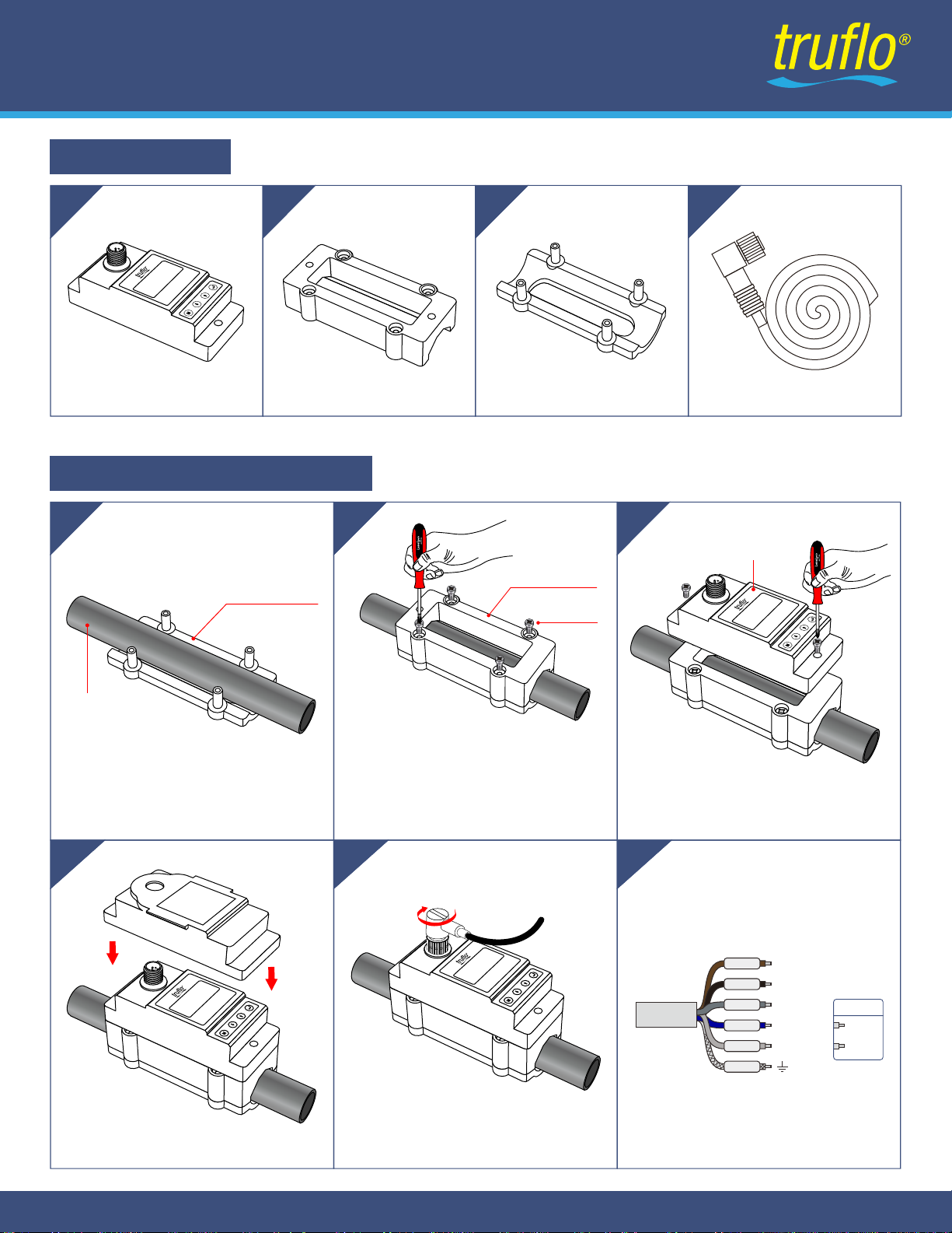
Sensor Body
Make sure no dirt, paint, or other
stains on the surface of the tube. Then
position the Lower Bracket on the pipe.
Align the Upper Bracket to the pipe position.
Magnets will hold brackets in place.
Using the mounting screws connect the
Upper and the Lower Brackets together.
Ensure that the parts are snug,
but DO NOT over-tighten.
Upper Bracket Lower Bracket M12 Cable
Position the display over the Upper
Bracket and connect using the mounting
screws. DO NOT over-tighten.
Install Polycarbonate Cover Connect M12 Cable
Wiring Diagram
Pipe
Lower Bracket
Display
6
23-0166 © Icon Process Controls Ltd.
Clamp-On Ultrasonic Flow Meter
UltraFlo®500 Series
Components
Installation and Connection
Screw
Upper Bracket
UltraFlo-500
www.iconprocon.com
UltraFlo-500
www.iconprocon.com
UltraFlo-500
www.iconprocon.com
DC+
Brown
Black
Gray
Blue
White
Shield
4-20mA+
RS485 A
RS485 B OCT+
OCT-
Option
DC-/4-20mA-
UltraFlo-500
www.iconprocon.com

SQ 0
23:22:18
GPM
8.635
Net 723.58 GAL
UltraFlo-500
www.iconprocon.com
Mounting Screw
Mounting Screw
M12 Connector
Flow Rate
Net Totalizer
Bright LCD Display
Keypad
When connected to a VDC Power Supply the Ultrapro 500 will begin to run self-diagnosis program
Follow these Guide Lines when using the Flow Meter Keypad:
SQ value is short for Signal Quality. It indicates the level of the signal detected. SQ value is indicated by
numbers from 0~99. 00 is the minimum signal could be detected and 99 represents the maximum.
Normally, the transducer position should be adjusted repeatedly and coupling compound should be
checked frequently until the signal quality detected is as strong as possible.
Press to Enter the Programming Mode or to return to the previous menu during programming.
Press to Scroll Up or Down
Press to move to the Next Digit
Press to Select Digits (0-9)
Press to Confirm Selection.
SQ 99
Net 723.58
GAL
GPM
01:58
3.368
7
23-0166 © Icon Process Controls Ltd.
Clamp-On Ultrasonic Flow Meter
UltraFlo®500 Series
Panel Function
Keypad Functions
Powering ON
Signal Quality (SQ value)
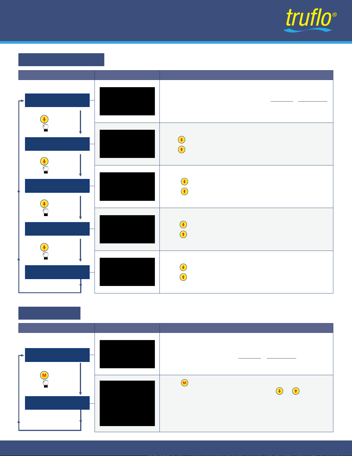
When power is on, the flow meter will display Flow Rate / Net Totalize
r
.
Signal quality & Time.
OPERATIONDISPLAY
STEPS
Main Display
Press Key
Totalizer
SQ 99
Net 768.89GAL
GPM
12:30:18
3.368
SQ 99
S.ToT
23.89
GAL
GPM
12:30:18
3.368
Press to Display Run time / Day Totalizer / Month Totalizer / Year Totalizer
Press to Return to Previous Menu.
Press Key
Press Key
Flow Rate / S.TOT Totalizer
Press Key
Flow Rate / Velocity / Net Totalizer
Press to Display Flow Rate / S.TOT Totalizer
Press to Return to Previous Menu.
Velocity / Net Totalizer
Press to Display Velocity / Flow Rate / Net Totalizer
Press to Return to Previous Menu.
Runtime
Year
GAL
Day GAL
Mth. GAL
216h
79.068
3839.8
3768
SQ 99
Net GAL
f/s
GPM
Vel
Flow
12:30:18
1.068
3.339
768.89
Press to Display Velocity / Net Totalizer,
Press to Return to Previous Menu.
8
23-0166 © Icon Process Controls Ltd.
Clamp-On Ultrasonic Flow Meter
UltraFlo®500 Series
Display Description
Power on Main Display shows
Flow Rate & Net Totalize
r
OPERATIONDISPLAY
STEPS
Main Display
Press Key
Setup Menu
Press to Display Setup Menu.
The following options are available (using the or Buttons)
0. Pipe parameter
1. System setting
2. Calibration
3. Output setting
4. History data
Setup menu
0. Pipe parameter
1. System setting
2. Calibration
3. Output setting
4. History data
Setup Menu
20-03-18
Net
768.89
GAL
f/s
12:30
1.868
SQ 99
Net 768.89GAL
GPM
12:30:18
3.368

OPERATIONDISPLAY
STEPS
Setup menu
Press to Key
Pipe Parameter
Press to display Setup menu.
The following options are available (using the or buttons)
0. Pipe Parameter
1. System Setting
2. Calibration
3. Output Setting
Setup menu
Press , Select 0.Pipe parameter, then to Display :
The following options are available (using the or buttons)
0. Outer diameter
1. Wall thickness
2. Material :
Press or can option PVC, Carbon steel, Steel,
Copper, PVDF, PFA, PTFE, PU, Aluminum.
3. Fluid type :
Press
or
to choose between Water, Sea Water, Oil...other.
Pipe Setting
0. Outer diameter
1. Wall thickness
2. Material
3. Fluid type
0. Pipe parameter
1. System setting
2. Calibration
3. Output setting
4. History Data
OPERATIONDISPLAY
STEPS
Setup Menu
Press to Key
System Setting
Press to display Setup menu.
The following options are available (using the or buttons)
0. Pipe parameter
1. System setting
2. Calibration
3. Output setting
Setup menu
Press , Select 1. System setting then to display:
The following options are available (using the or buttons)
0. System Unit : Press or to choose between Metric, English.
1. Flow Rate Unit :
Press or
to choose between m3/h, LPM, GPM, LPH.
2. Total Unit : Press or to choose between m3, L, GAL.
3. Total Reset : Press then Parameters will be reset.
4. Time Set :
When modifying, the default is 30 seconds.
Generally, it is unnecessary to modify date &
time as the system is equipped with a highly
reliable perpetual calendar chip.
Next Page
System setting
0. System Unit
1. Flow Rate Unit
2. Total Unit
3. Total Reset
4. Time Set
5. System Lock
6. System INFO
7. Display dir
8. Damping
9. Display format
0. Pipe parameter
1. System setting
2. Calibration
3. Output setting
yy-mm-dd hh:mm
19-06-20 12:30
9
23-0166 © Icon Process Controls Ltd.
Clamp-On Ultrasonic Flow Meter
UltraFlo®500 Series
Pipe Parameter Setup Menu
System Setting Setup Menu

OPERATIONDISPLAY
STEPS
System Setting
5. System lock
System setting
0. System Unit
1. Flow Rate Unit
2. Total Unit
3.Totalizer Reset
4. Time Set
5. System Lock
6. System INFO
7. Display dir
8. Damping
9. Display format
System lock
System Unlocked
System Unlocked
ENT to lock
ENT key word
0000
System lock
System locked OK
System lock
System locked
System lock
ENT to unlock
ENT key word
0000
System lock
System Unlocked OK
Once the system is locked, any modifications to the system are
prohibited, but the parameter is readable. "Unlock" using your
designated password. The password is composed of 1 to 4 numbers.
7. Display dir
Display dir
0. Normal
1. Inversion
Select the display direction of the screen,
which can be rotated by 180 degrees.
Display Inversion (180 degree rotation) to be
mentioned as a key feature
Previous Page
8 . Damping
Damping
003
When the flow regime is unstable and the display value changes
greatly, damping can be set to adjust the measurement response
speed of the product. The unit is in seconds.
9. Display format
Display format
0. x 0.001
1.x 0.01
2.x 0.1
The display digit of the measured value can be set through the zoom
function. It is displayed after the decimal point by default 3 digits.
You can choose to display 2 digits after the decimal point, 1 digit after
the decimal point and 0 digit after the decimal point.
10
23-0166 © Icon Process Controls Ltd.
Clamp-On Ultrasonic Flow Meter
UltraFlo®500 Series
6. System INFO
System INFO
Flowmete
SN:30001399 V1.00
Manual Totalizer
ENT To Start
Manual Totalizer
ENT To Stop
1.239 m3/h
SQ99 1.056L
Display serial number (SN) of the meter. This SN is the only one
assigned to each flow meter ready to leave the factory.
The factory uses it for files setup and for management by the user.
Press 5 times to enter Manual Totalizer; The manual totalizer is
a separate totalizer. Press to start, and press to stop it.
It is used for flow measurement and calculation.
Manual Totalizer
ENT To Restart
1.239 m3/h
SQ99 1.056L

Next Page
11
23-0166 © Icon Process Controls Ltd.
Clamp-On Ultrasonic Flow Meter
UltraFlo®500 Series
OPERATIONDISPLAY
STEPS
Setup Menu
Press to Key
Calibration
Press to display Setup Menu.
The following options are available (using the or buttons)
0. Pipe parameter
1. System setting
2. Calibration
3. Output setting
Setup menu
Press , Select 2. Calibration, then to display:
The following options are available (using the or buttons)
0. Scale factor
Calibration
0. Scale factor
1. 4-20mA CAL
2. Set Zero
3. Low flow Cut
4 . Manual zero
5 . HiAGC
0. Pipe parameter
1. System setting
2. Calibration
3. Output setting
Refers to the ratio between the “actual value” and “
reading value”. For example, when the measurement
is 2.00, and it is indicated at 1.98 on the instrument,
the scale factor reading is 2/1.98.
This means that the best scale factor constant is 1.01.
Calibration Setup Menu
4mA Calibrate
25492
Scale factor
1.000
20mA Calibrate
4555
Set zero
Ent to set zero
Reset zero
Set zero
SQ 88
Vel 0.035 f/s
Waitting...
This function can prevent that when the pump stops working and the
liquid flows at a low speed in the pipe, data accumulation error
caused by continuous reading of flow meter. Input is generally
recommended 0.05f/s as the low flow cut-off point. The low flow
cut-off value is independent of the measurement results.
After setting, return to the main interface and the flow is "0".
If you return to the main interface, the flow is not "0", the setting is
unsuccessful. Check whether the installation is correct or not.
1. 4-20mA CAL
2. Set Zero : Press ; reset “Zero Point” which was set by the user.
Check if the current loop has been calibrated before leaving the
factory. Press move to display 4mA or 20mA , and at the
same time, check with an ammeter to verify that Current Loop
output displayed values. It is necessary to re-calibrate the current
loop, if over the permitted tolerance.
The displayed value has no meaning, but is only used for internal
records. Correct only by up and down Key operation, check the
displayed value of ammeter (multimeter).
Low flow cut
0.0500 f/s
3. Low flow cut : Flow rate falls below the low flow cutoff value.

Calibration
Calibration
0. Scale factor
1. 4 & 20mA CAL
2. Set Zero
3. Low flow Cut
4. Manual zero
5. HiAGC
6. Negative Flow
Previous Page
OPERATIONDISPLAY
STEPS
Setup Menu
Press to Key
Output Setting
Press to display Setup menu.
The following options are available (using the or buttons)
0. Pipe parameter
1. System setting 2. Calibration
3. Output setting
Press , Select 3. Output setting, then to display:
The following options are available (using the or buttons)
0. RS 485 Setup
Output setting
0. RS485 Setup
1. 4-20mA range
2. Alarm value
3. OCT output
4. OCT multiplier
Setup menu
0. Pipe parameter
1. System setting
2. Calibration
3. Output setting
4. History data
Then select : None. Data length : 8 Stop bit is fixed length.
Factory default value for serial port parameter is ''9600, 8, None,1''
Next Page
12
23-0166 © Icon Process Controls Ltd.
Clamp-On Ultrasonic Flow Meter
UltraFlo®500 Series
Output Setting Setup Menu
4mA value
0.00
20mA value
15.00GPM GPM
Generally, pipes made of SS304 or SS316 are with wall thickness of
more than 2mm. In practical use, it will receive false signals due to
the interference of pipe wall signals, It is recommended that the low
flow rate should be cut off at 0.08m/s or above.
4. Manual zero
Manual zero
0.0000 m3/h
High gain switch do not needs to be set generally,
could try to switch on for special pipes with weak
signal detected.
This method is not commonly used and is only
suitable for experienced operators. It is not suitable
for other parties. Manually input the value and add
it to the measured value to obtain the actual value.
This window is used to set RS 485 serial port. It must
match the equipment's connected parameters.
First select baud rate: 2400, 4800, 9600, 19200
are selectable
5. Hi AGC
Hi AGC
0. OFF
RS485 Setup
0.Network addr
1.RS485 Baudrate
2.RS485 Parity
3.RS485 Stopbits
1. 4-20mA range
Set the Current Loop output value according to the flow value at
4mA, and 20mA. The flow unit is GPM.
OPERATIONDISPLAY
STEPS
Output Setting
Output setting
0. RS485 Setup
1. 4-20mA range
2. Alarm value
3. OCT output
4. OCT multiplier
Previous Page
Enter the low alarm value; any measured flow lower than the low value,
will activate the alarm in the OCT hardware or relay output signal.
Enter the high alarm value; any measured flow higher than the high
value, will activate the alarm in the OCT hardware or relay output signal.
Alarm value
0. Low value
1. High value
2. Alarm Value (Optional)
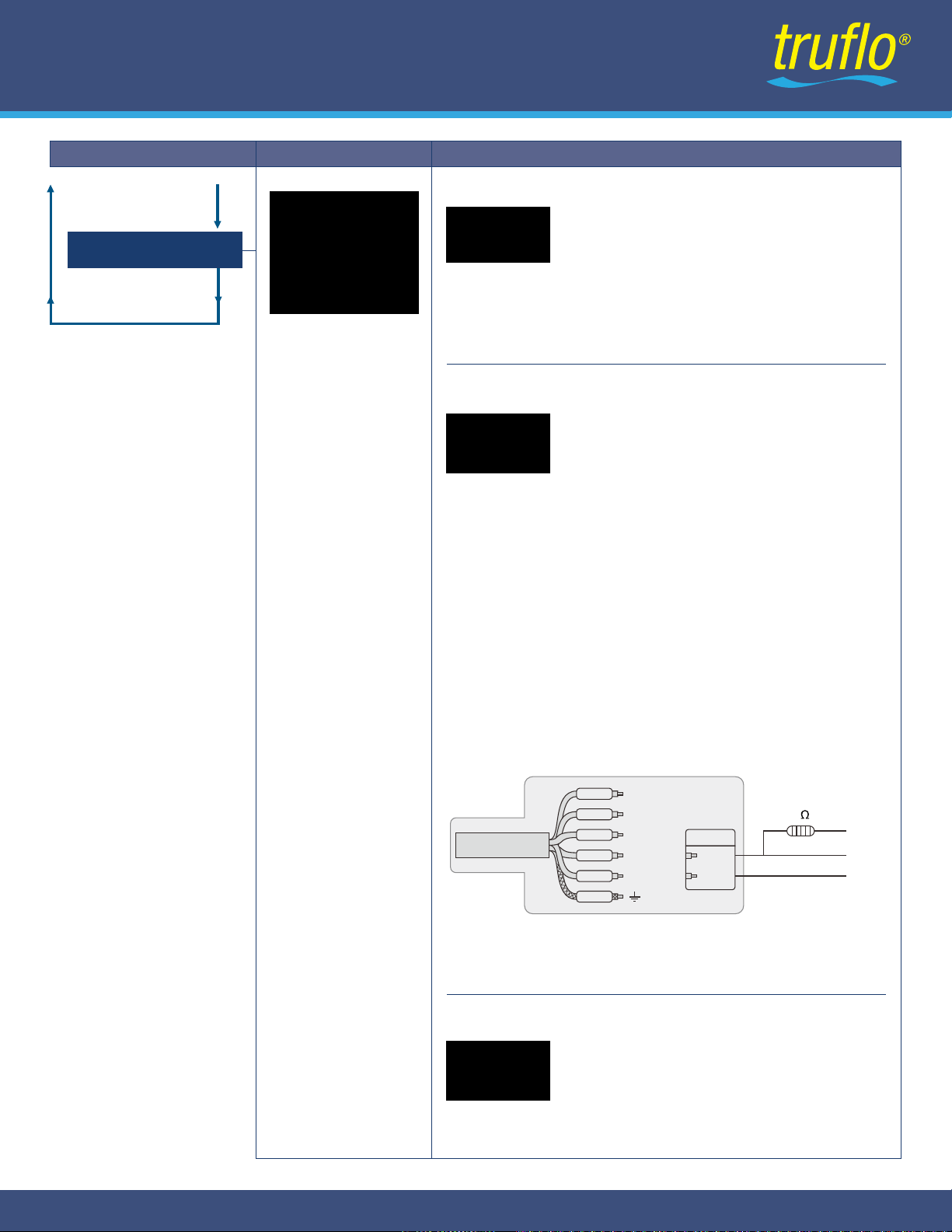
The OCT output in the flow meter is a kind of isolated collector open
circuit output with programmable open and close qualifications.
The user can program the open and close functions under the
following conditions: the system alarm signals are being activated or
the totalizer pulse is being transmitted.
Pulses are cumulative output, and the equivalent of each pulse is
0.01L~ 100m3, It can be set through the menu.
The maximum number of pulses output per second is 40.
To select OCT output, an external 5-10K pull-up resistor shall be
connected at the OCT + end; Add a 5-24vcd power supply at VCC
and com ends, as shown in the figure:
OCT Wiring Diagram:
OCT output
0.Total Pulse
1.Alarm output
2.No Signal
3. OCT output (Applicable to OCT output model)
Select OCT pulse output multiple
OCT multiplier
0. x0.001
1. x0.01
2. x0.1
4. OCT multiplier (Applicable to OCT output model)
13
23-0166 © Icon Process Controls Ltd.
Clamp-On Ultrasonic Flow Meter
UltraFlo®500 Series
DC+
Brown
Black
Gray
Blue
White
Shield
Resistance
5-10k 1/4W Vcc
Signal
Com
4-20mA+
RS485 A
RS485 B OCT+
OCT-
Option
DC-/4-20mA-

OPERATIONDISPLAY
STEPS
Setup Menu
Press to Key
History Data
Press to display Setup menu.
The following options are available (using the or buttons)
0. Pipe parameter
1. System setting
2. Calibration
3. Output setting
4. History data
Setup menu
Press , Select
4. History data
, then to display:
0. By Day : Display Totalizer flow for days.
1. By Month : Display Totalizer flow for months.
2. By Year : Display Totalizer flow for years.
History data
0.By Day
1.By Month
2.By Year
0. Pipe parameter
1. System setting
2. Calibration
3. Output setting
4. History data
14
23-0166 © Icon Process Controls Ltd.
Clamp-On Ultrasonic Flow Meter
UltraFlo®500 Series
Data Logging Setup Menu
Model Pipe OD OD Range A (mm) Max C(mm)
UF500-15 16.5 - 23 86 106
UF500-25 30-35 91 106
UF500-40 48-54 110 106
UF500-50 58-68 126 130
UF500-50 88-96 154 150
UF500-100
½"
1"
1-½"
2"
3"
4" 108-116 177 174
B(mm)
52
58
78
91
119
143
Dimensions
A
C
A
B
42

Icon Process Controls
warrants to the original purchaser of its products that such products will be free from defects in materials
and workmanship under normal use and service in accordance with instructions furnished by
Icon Process Controls
for a period
of one years from the date of sale of such products.
Icon Process Controls
obligation under this warranty is solely and exclusively
limited to the repair or replacement, at Icon's option, of the products or components, which Icon examination determines to its
satisfaction to be defective in material or workmanship within the warranty period.
Icon Process Controls
must be notified
within thirty (30) days pursuant to the instructions below of any claims of lack of conformity under this warranty. Any product
repaired under this warranty will be warranted only for the remainder of the original warranty period. Any product provided as a
replacement under this warranty will be warranted for the full 1 year from the data of sale.
Warranty
Products cannot be returned to
Icon Process Controls
without Icon's prior authorization. To return a product that is thought to
be defective please submit a customer return (MRA) request form and follow the instructions therein. All warranty and non-
warranty product returns to
Icon Process Controls
must be shipped prepaid and insured. Icon will not be responsible for any
products lost or damaged in shipment.
Returns
This warranty does not apply to products which:
1)
Are beyond the warranty period or are products for which the original purchaser does not follow the warranty procedures outlined above;
2) Have been subjected to electrical, mechanical or chemical damage due to improper, accidental or negligent use;
3) Have been modified or altered;
4) Anyone other than service personnel authorized by Icon have attempted to repair;
5) have been involved in accidents or natural disasters;
6) Are damaged during return shipment to Icon Process Controls.
Icon Process Controls reserves the right to unilaterally waive this warranty and dispose of any product returned to Icon where :
1) There is evidence of a potentially hazardous material present with the product;
2)
The product has remained unclaimed at Truflo for more than 30 days after Icon Process Controls has dutifully requested disposition.
This warranty contains the sole express warranty made by
Truflo
in connection with its products. ALL IMPLIED WARRANTIES,
INCLUDING WITHOUT LIMITATION, THE WARRANTIES OF MERCHANTABILITY AND FITNESS FOR A PARTICULARPURPOSE, ARE
EXPRESSLY DISCLAIMED. The remedies of repair or replacement as stated above are the exclusive remedies forthe breach of this
warranty. IN NO EVENT SHALL LEVELPRO BE LIABLE FOR ANY INCIDENTAL OR CONSEQUENTIAL DAMAGESOF ANY KIND
INCLUDING PERSONAL OR REAL PROPERTY OF FOR INJURY TO ANY PERSON. THIS WARRANTYCONSTITURES THE FINAL,
COMPLETE AND EXCLUSIVE STATEMENT OFWARRANTY TERMS AND NO PERSON IS AUTHORIZED TO MAKE ANY OTHER
WARRANTIES OR REPRESENTATIONS ONBEHALF OF Icon Process Controls.
If any portion of this warranty is held to be invalid or unenforceable for any reason, such finding will not invalidate any other provision of this
warranty
For additional product documentation and technical support visit www.iconprocon.com | e-mail: sales@iconprocon.com
Limitations
15
23-0166 © Icon Process Controls Ltd.
Clamp-On Ultrasonic Flow Meter
UltraFlo®500 Series
Warranty, Returns & Limitations

This manual suits for next models
5
Table of contents
Other truflo Measuring Instrument manuals

truflo
truflo TKS Series Instruction manual

truflo
truflo TK Series User manual

truflo
truflo TIB Series User manual

truflo
truflo TKB Series Instruction manual

truflo
truflo ULTRAFLO 5000 User manual

truflo
truflo TKB Series Instruction manual

truflo
truflo OBS-LE Series User manual

truflo
truflo TIP Series User manual
truflo
truflo ICON TIR Series User manual

truflo
truflo TKB Series User manual


