Metaflex Medicare EI1 2.0 User manual

Metaflex Doors Europe BV
Ambachtsstraat 11
NL
- 7122 MP Aalten
T +31 88 14 14
900
info@metaflexdoors.com
www.metaflexdoors.com
Installation manual
Metaflex Medicare EI1 2.0
202571

Page 2 of 27
Doc QA No 10.20.3
3 Rev. 03 | 08.03.2023
Table of Content
1. Foreword ............................................................................................................................................................ - 3 -
2. Specifications...................................................................................................................................................... - 3 -
3. Safety guidelines ................................................................................................................................................ - 4 -
4. Transport and storage........................................................................................................................................ - 4 -
5. Fastening materials............................................................................................................................................ - 4 -
6. Tools required..................................................................................................................................................... - 5 -
7. Necessary PPE .................................................................................................................................................... - 5 -
8. Installation steps ................................................................................................................................................ - 6 -
8.1 Dimension check ................................................................................................................................................ - 6 -
8.2 Frame assembly.................................................................................................................................................. - 7 -
8.3 Rail system installation..................................................................................................................................... - 11 -
8.4 Door Leaf Assembly .......................................................................................................................................... - 13 -
8.5 Opener (optional) ............................................................................................................................................. - 17 -
8.6 Adjusting door leaf and drive belt .................................................................................................................... - 18 -
8.7 Guiding rollers assembly .................................................................................................................................. - 20 -
8.8 Canopy.............................................................................................................................................................. - 23 -
9. Operations & Maintenance.............................................................................................................................. - 26 -

Page 3 of 27
Doc QA No 10.20.3
3 Rev. 03 | 08.03.2023
1. Foreword
This manual describes the assembly of a Metaflex Medicare EI1 sliding door. The information in this manual is important
for the good and safe functioning of the door system. Read this user manual thoroughly from cover to cover. Metaflex
Doors Europe (MDE) urges that all new users (operators, installers, maintenance staff and where applicable cleaning
staff) should receive training, for which this user manual may serve as a basis.
MDE advises that the original copy, including its attachments, should be stored in a safe, central place. Another copy of
this manual should be stored close to the apparatus in the workspace.
The assembly instructions are intended for technical personnel.
The maintenance instructions assume that the maintenance staff have been authorized by Metaflex Doors Europe.
This warning sign indicates points which require special attention during installation.
2. Specifications
Product description
Serial number: Indicated on the component ID label
Variants: Metaflex EI1 frame
Areas of application
Healthcare facilities, hospitals, pharmaceutical.
Dimensions
Variable clear opening width x clear opening height, up to a maximum of 2000 x 2700 mm.
Lifespan
10 years when maintained according to Metaflex Doors Europe's maintenance guidelines.
Weight
The weight of a Medicare EI1 2.0 door system depends on the clear width and height. The maximum weight of the door
leaf is 320 kilograms.
Assembly options
Panel wall (through the wall), provided they are suitable for carrying the weight of the door.

Page 4 of 27
Doc QA No 10.20.3
3 Rev. 03 | 08.03.2023
3. Safety guidelines
General guidelines
1. Always wear dry work clothes and safety shoes.
2. Work may only be carried out if the local legal regulations are observed.
3. Always switch the circuit breaker/power supply off and place warning signs when carrying out work
so that the door cannot be operated.
4. Before starting, check that the on/off switch is switched to the 'OFF' position. Only insert the plug
once assembly has been completed.
5. Ensure that fingers do not become trapped, especially:
•During installation/adjustment of the guide rollers.
•When installing/adjusting the toothed belt of the motor/return pulley.
•Between the end stop and the door.
•Between the rollers and the rail.
•Between the frame and flush handle on the inner side of the door leaf.
6. Use only original components and accessories.
7. Do not alter the way in which the door is constructed or controlled. If done so, the manufacturer warranty will be
void. All claims on the warranty due to the failure at the consumer unit will be rejected.
Incorrect setting of the opening direction has a consequence on the safety systems. The changing of parameters
concerning DIN direction and automation type can lead to improper functioning of the automation and/or the door and
may cause damage.
Safety in special situations
Take extra safety precautions in all settings, for example in surroundings where people are unaware of the risks of
becoming trapped. In order to prevent this, the following facilities are available:
•Radar and/or a light curtain detecting the opening.
•Light curtain sensor detecting the door when operating.
•Screening off of the area in which the door operates.
4. Transport and storage
Transport
Metaflex Doors takes care when packing the products. The door (system) and/or automation are shipped in crates or
on pallets. During transport, no other goods may be stacked on the Metaflex packaging. Be careful not to shake the
packaging.
Storage
The door (systems) and/or automation should be stored in their original packaging in a dry and frost-free environment
until installation.
5. Fastening materials
202569 Assembly kit frame EI1 2.0
200234 Assembly kit MF5 rail
VMF10063 Guiding roller set medical grounding
200235 Assembly kit MF5 hook lock

Page 5 of 27
Doc QA No 10.20.3
3 Rev. 03 | 08.03.2023
6. Tools required
7. Necessary PPE
Ensure to proceed with installation wearing specialized safety clothing/equipment.
Ø 5.3
Ø 7.8 TX-40
3/8”, 13mm
PH2
S13 / S17
Safety goggles
Helmet
Hearing protection
Safety shoes
Gloves

Page 6 of 27
Doc QA No 10.20.3
3 Rev. 03 | 08.03.2023
8. Installation steps
Follow the described sequence and, if in doubt, contact Metaflex Doors Europe to clarify. DO NOT
IMPROVISE as the doors have to be assembled according to certified guidelines.
8.1 Dimension check
Check the dimensions and proceed.
Check the width (B), the height (H) and the wall thickness (D) of the door opening with floor plan.
Clear opening data available on customer drawing.
B = Clear opening width
H = Clear opening height
D = Wall thickness
Check if the finished floor and walls are level and straight. Maximum tolerances ±2 mm.
H
B
D

Page 7 of 27
Doc QA No 10.20.3
3 Rev. 03 | 08.03.2023
8.2 Frame assembly
Step 1: Align the 3 frame components (left, right and top) and connect to eachother using the click-in construction as
shown below.
Step 2: Once the frame components are connected, align the frame around the wall opening and temporary fixate the
frame with te help of bar clamps. Make sure that the bar clamps have soft clamping surfaces that prevent damaging the
door frame and/or the finished wall. Use a spirit level to check all frame components are installed correctly.
Page 8 of 27
Doc QA No 10.20.3
3 Rev. 03 | 08.03.2023
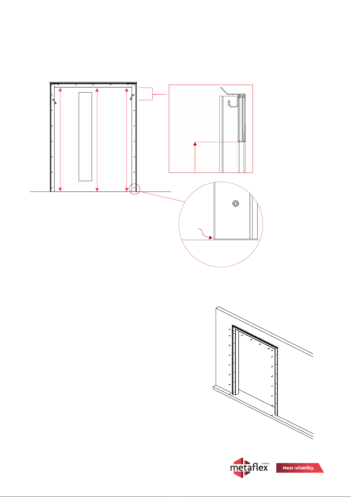
Step 3: Measure the distance from the finished floor level to the inside frame heightat the 3 points (see image below).
This distance must be “Clear Opening Height”. Make sure all three positions are within tolerance by adjusting the frame
along the wall. In the ideal situation, the wall frame should be 4 mm free from the finished floor level.
Step 4: Pre-drill the holes before installing the screws with drill Ø 5.3 mm.
Fix the frame to the wall using screws (6,5 x 50 mm self-tapping screw). Make sure the base of the frame is free from
the finished floor level.
Tool: 3/8” Hexagon socket
►In case of medical grounding: Slide the plastic covers over the
mounting screws. After securing the frame, measure whether the
frame is grounded.
Clear Opening Height
Side-view
Frame
Floor
4 mm gap

Page 9 of 27
Doc QA No 10.20.3
3 Rev. 03 | 08.03.2023
Step 5: Using the silicone sealant from assembly kit 202569, surrounding (path along yellow highlight) the
frame, seal both inside and outside to make it airtight and smoke resistance.

Page 10 of 27
Doc QA No 10.20.3
3 Rev. 03 | 08.03.2023
Step 6: Attach the Promaseal on the frame. Cut the Promaseal strips tothe according sizes. Attach the Promaseal on the
frame. Cut the Promaseal strips to the according sizes. The strips have a maximum length of 2150 mm. Therefore, devide
one 60 mm strip in length over the two lateral frame parts. Start fixating the lateral strips from the top, so that the seam
between the strips is not at visual height.
•The vertical strips (60mm wide) should be taped approximately 40mm from the inside of the frame edge.
•Horizontal strip (40mm wide) should be level with the top labyrinth as shown in the following figure.
60mm Promaseal
40mm Promaseal
60mm Promaseal

Page 11 of 27
Doc QA No 10.20.3
3 Rev. 03 | 08.03.2023
8.3 Rail system installation
ATTENTION: PLEASE USE CAUTION WHEN INSTALLING. FALL HAZARD!
Step 1: Ensure that the fire-resistant strip is mounted behind the rail, should be already attached to
create an offset of 6 mm between wall and rail. Rest the rail on top of the wall frame (rail support profile), and align it
with the rail support profile on the opener side.
Step 2: Use the holes in the rail as a reference for
drill point coordinates.
Before marking any hole points, use a spirit level
to check if the rail is horizontally levelled.
1. Secure the rail to the first hole at opening
side using bolts from assembly kit 200234.
Use plastic bushes over the mounting
screws if the door system must be set up
grounded medicaly.
2. Keep the rail level and secure the end of
the rail.
3. Mount the remaining bolts to secure the
rail.
Tool: 13mm Hexagon socket wrench
►In case of medical grounding: Use plastic
covers over the mounting screws if the door
system must be set up grounded medicaly.
fire-resistant strip
1
2
3

Page 12 of 27
Doc QA No 10.20.3
3 Rev. 03 | 08.03.2023
Step 3: Unthighten the two bolts of the endstop at the opening side and slide
the endstop near the clear opening. Correctly install both fire hooks to the wall
through the rail using the self-tapping screws. All the required fastening
material are in assembly kit number 200235.
Tool: 13mm wrench, TX-40
►In case of medical grounding: Use plastic covers over the mounting screws
if the door system must be set up grounded medicaly.
Step 4: Slide the end stop back in the previous position and thigten the bolts. Maintain a distance of 15 mm from the
rail end and lock it in position using hex nuts. The stopper can also be manually adjusted by rotating the stopper knob.
Tool: 13mm wrench
15 mm
Page 13 of 27
Doc QA No 10.20.3
3 Rev. 03 | 08.03.2023
8.4 Door Leaf Assembly
ATTENTION: PLEASE HANDLE WITH CARE
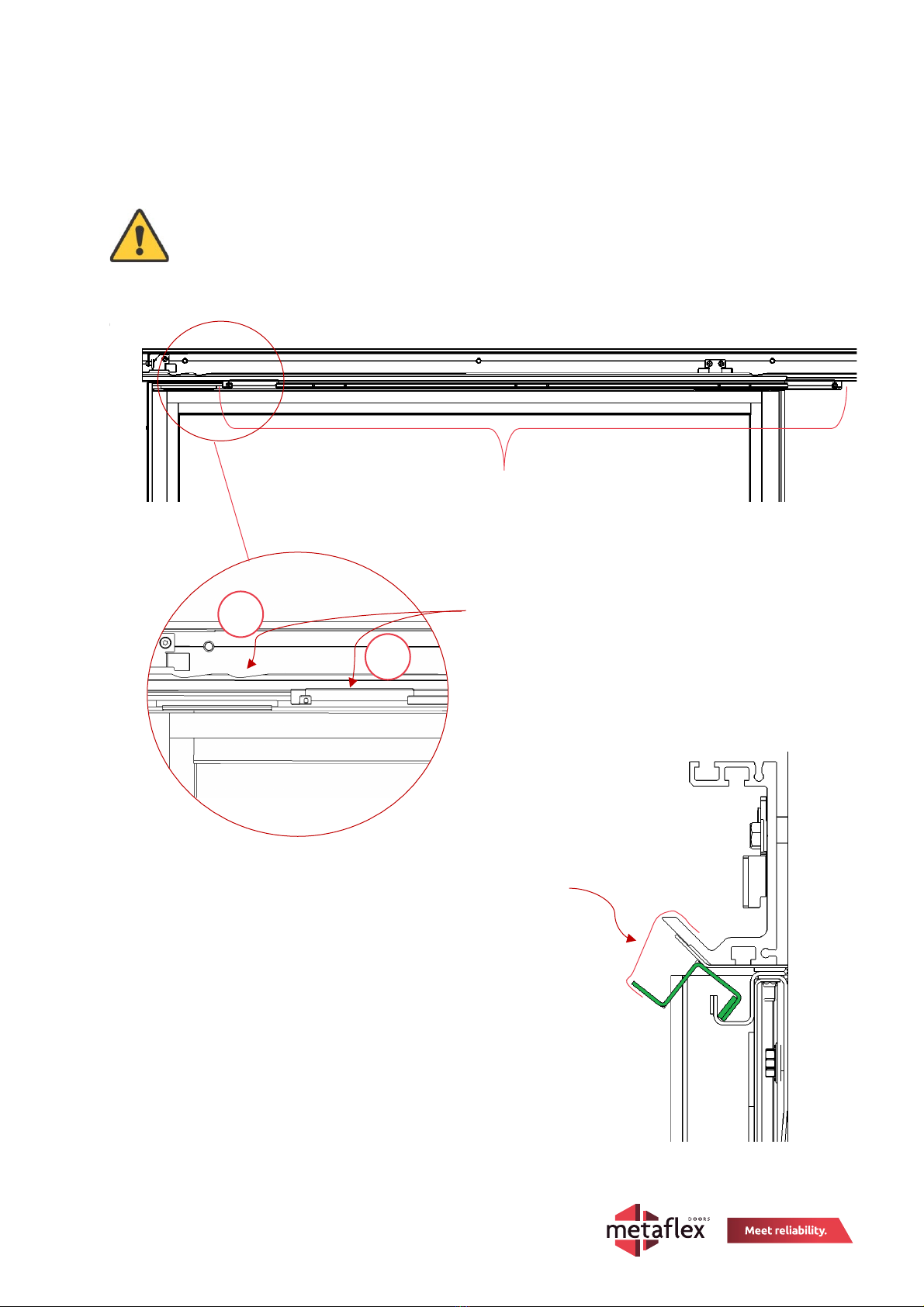
Step 1: Prior installing the door leaf, first place the “door leaf top labyrinth” inside the wall frame labyrinth.
Keep the labyrinth in an upwards placed position with the help of tape.
Position the cutouts of the labyrinths away from the rail indentations.
Typ hier uw vergelijking.
Use tape on several
positions to hold the
labyrint temporary in
an upwards position
Door leaf labyrinth
1. Cutouts of the labyrinths away from the
2. rail indentations
1
2
Page 14 of 27
Doc QA No 10.20.3
3 Rev. 03 | 08.03.2023
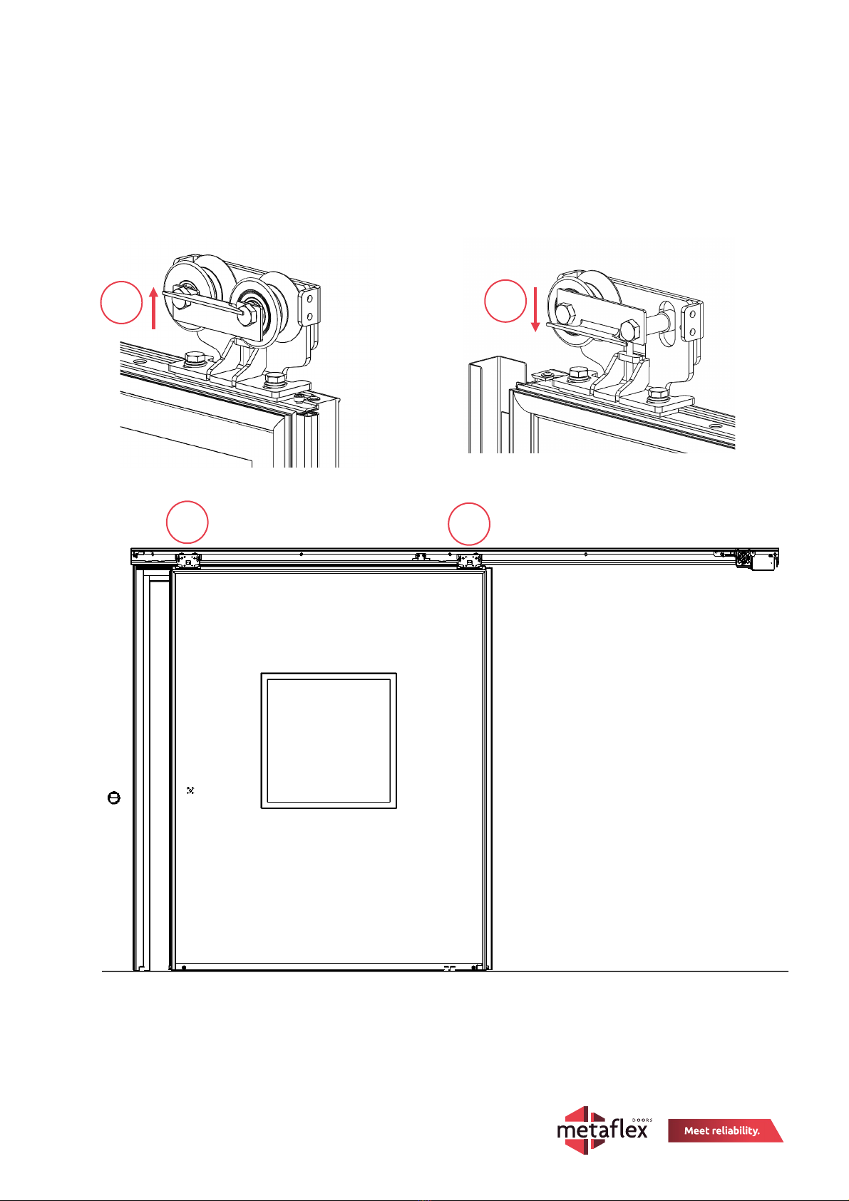
Step 2: Mount the track trolleys on top of the door leaf with M10 x 25 stainless steel bolts already mounted in the door.
Ensure that the hooks [1] on the track trolleys are placed on the correct side. At the opening side, the hook should be
placed upwards. On the closing side the hook should be placed downwards.
Lock it just, but not all the way, for later adjustment
Tool: 17mm wrench
1
2
1
2

Page 15 of 27
Doc QA No 10.20.3
3 Rev. 03 | 08.03.2023
Step 3: Stand the door upright in front of the frame. Make sure that the track trolleys are aligned with the cutouts in
the labyrinth. Lift the door into the rail making sure the wheels positioned onto the rail.
Alignment of the
labyrinth cutout and
track trolley
Wheel position after
lifting the wheels onto
the rail.
Page 16 of 27
Doc QA No 10.20.3
3 Rev. 03 | 08.03.2023
Step 4: Remove the tape thats keeping the labryint it in its upward position and install the labyrint on the door leaf with
the help of stainless steel M6 x 16 Hexagon socket head screws.
Tool: 5mm Allen key
Page 17 of 27
Doc QA No 10.20.3
3 Rev. 03 | 08.03.2023
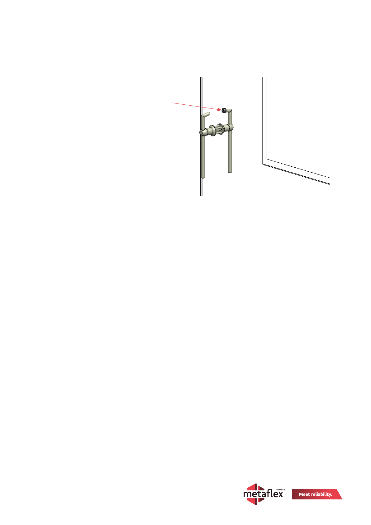
8.5 Opener (optional)
Step 1: Install the openers on the door body using the instruction manual included.
The black cap used in the opener is placed on
the inside wall opening to damper if any
contact with door frame.

Page 18 of 27
Doc QA No 10.20.3
3 Rev. 03 | 08.03.2023
Adjusting depth: Make sure that the door is in
the open position. The distance between the
wall surrounding seal and the Promaseal (red)
strip on the frame should be 3 to 4 mm.
Tool: 17mm wrench (Torque: 40 Nm)
NOTE: When in Closed position make sure the EPDM is pressed against the Promaseal strip and the floor to create
air tight passage
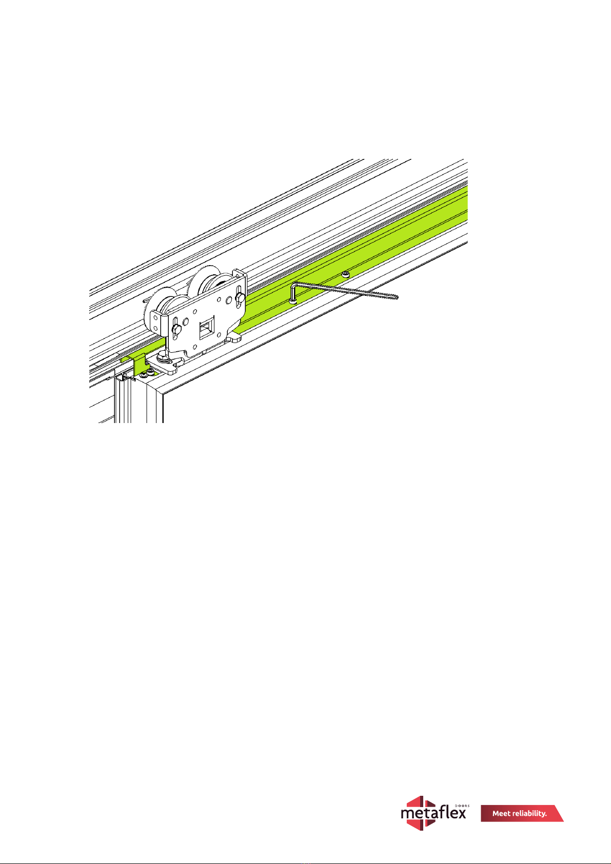
8.6 Adjusting door leaf and drive belt
Adjust both the track trolleys so that no fouling occurs during operation and the door is fully sealed when in closed
position.
Adjusting height: Make sure that the door is in the open position
and the trolleys are out of rail indents. The bottom floor seal should
be at a distance of ±4 mm from the finished floor. Before adjusting
the height with the M6 bolt, untighten the M8 bolts located on the
opposite side [1]. Tighten the M8 bolts after adjusingt the height.
Tool: 5mm Allen key, 13mm wrench
Note: The right wheel is missing, this is only a
representation for clear understanding of the
sequence.
It is also possible that a trolley is supplied
with two wheels, use the same procedure
mentioned above for adjustment.
1
2
Page 19 of 27
Doc QA No 10.20.3
3 Rev. 03 | 08.03.2023
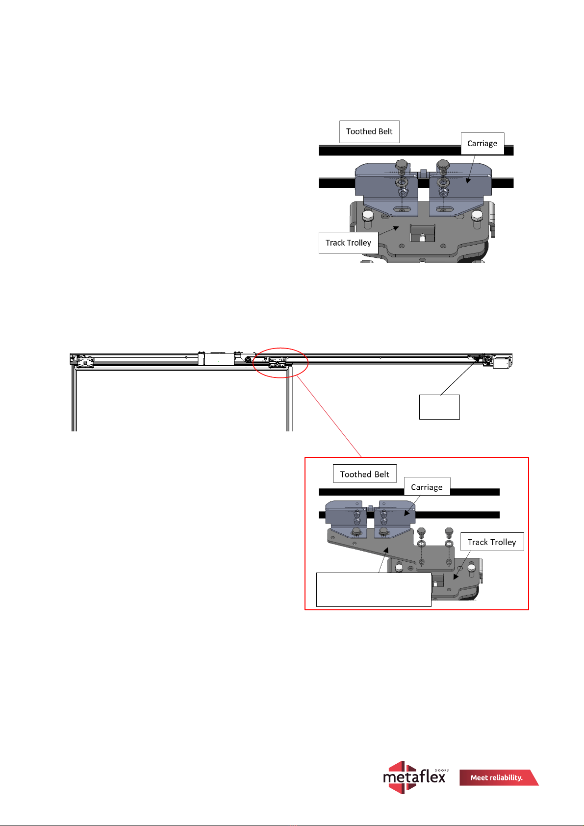
8.6.1 Carriage
Mount the carriage to the track trolley (M8x10).
Tool: 13mm wrench (Torque: 25,5Nm)
Alternatively if the motor is positioned above the rail – Mount the Drive Support bracket including the Carriage to the
Track Trolley.
Tool: 13mm wrench (Torque: 20Nm)
Motor
Driver Support bracket (if
motor placed on top of rail)
Page 20 of 27
Doc QA No 10.20.3
3 Rev. 03 | 08.03.2023
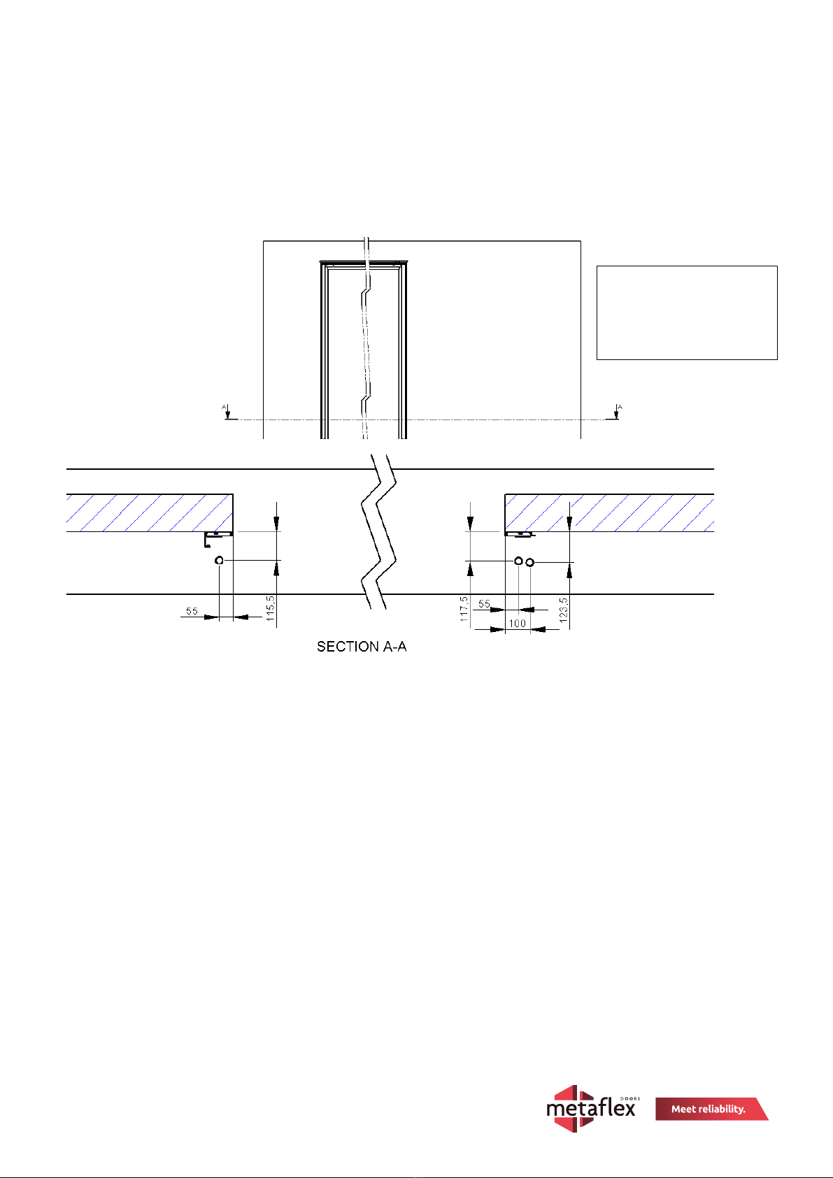
8.7 Guiding rollers assembly
Step 1: Open the door and mark the drill points on the floor. Then drill 3 holes of ø 10 mm each on the marked points.
►The positioning of the guiding rollers as shown below is indicational. Place the guiding rollers on sight to get a
proper sealing.
Guiding rollers – X With metal stud inside
Guiding rollers – Y
Without metal stud inside
X
X
Y
The below drill positions are
for Right opening doors.
For Left opening mirror the
direction.
This manual suits for next models
1
Table of contents
Other Metaflex Door Opening System manuals


Popular Door Opening System manuals by other brands


Genius
Genius MINY17 Assembling instructions

Tormax Automatic
Tormax Automatic Win Drive 2201 Instructions for use

Dahua
Dahua Unit VTO6221E-P user manual

B&D
B&D Smart Pro Quick operation guide

Assa Abloy
Assa Abloy Norton 6300 Series installation instructions

Assa Abloy
Assa Abloy SW200 Installation and service manual

EINHELL
EINHELL FH 70 operating instructions

SIMONSWERK
SIMONSWERK Anselmi AN 140 3D ALU installation instructions

Prismatibro
Prismatibro Prisma Button 800 installation manual

Siemens
Siemens RHOH quick start guide

Locinox
Locinox VERTICLOSE-RAIL Installation instructions manual

Iseo
Iseo ACE IS9100 Mounting instructions