Metal Samples Company MS4500E-HC User manual


Table of
Contents
I. Introduction ............................................................................................................................................ 1
A. General Description ................................................................................................................. 1
B. Principles of Operation ............................................................................................................ 1
C. Technical Specifications ........................................................................................................... 3
II. Start Up and Operation.......................................................................................................................... 4
A. Receiving the MS4500E-HC Data Logger ................................................................................. 4
B. Start Up .................................................................................................................................... 4
1. Port Details and Probe Connection............................................................................ 4
2. Power Up.................................................................................................................... 5
a. Safe Area Usage ............................................................................................. 5
b. Hazardous Area Usage .................................................................................... 6
c. Battery Replacement....................................................................................... 8
3. Setup and Operation..................................................................................................... 9
a. Select Probe ................................................................................................... 9
i. New Probe ................................................................................................ 10
ii. Existing Probe ........................................................................................... 10
iii. Delete Existing Probe................................................................................ 11
b. Make Measurement ..................................................................................... 12
c. Recall Readings.............................................................................................. 13
d. Delete Readings ............................................................................................ 14
e. Set Time & Date .......................................................................................... 15
f. Set Measurement Timer................................................................................ 16
g. Communications ........................................................................................... 17
h. Language ...................................................................................................... 23
i. Power Off ....................................................................................................... 23
j. Backlight On/Off............................................................................................. 23
C. Maintenance .......................................................................................................................... 24
1. Testing the MS4500E-HC High Resolution Data Logger with the Meter Prover...... 24
D. Troubleshooting..................................................................................................................... 25
III. Service and Warranty Information ..................................................................................................... 26
A. Warranty................................................................................................................................ 26
B. Obtaining Service and Returning the Instrument for Repair ................................................. 26
C. Instrument Repair Form......................................................................................................... 27
Appendix A – Revision History ................................................................................................................. 28
Appendix B – Hazardous area certification details .................................................................................. 29
Appendix C - Drawings ............................................................................................................................. 31
Control Drawing (Hazardous Area Wiring Diagram)................................................................... 32

1
I. Introduction
A. General Description
The MS4500E-HC is a hand-held, battery powered, corrosion meter capable of measuring and storing data
from all types of electrical resistance (ER) corrosion probes. The instrument is light weight,
microprocessor-based, and features a simple, menu-driven interface using a keypad and a backlit
graphical LCD display.
Corrosion rate measurements are made using the electrical resistance method. Essentially, the instrument
measures the resistance of the probe element which changes over time, as metal loss occurs. The rate of
change is directly proportional to corrosion rate. This method finds a wide variety of applications since it
can be used in conductive and nonconductive environments such as petroleum, chemical, water, soil, or
even atmosphere. The new high-resolution measurement of the MS4500E-HC detects smaller increments
of metal loss, providing faster response than traditional ER instruments.
After taking a reading, the instrument displays metal loss in mils and corrosion rate in mils per year (mpy).
The reading can then be stored to memory or discarded. All stored readings are automatically time and
date stamped. Readings are stored to non-volatile Flash memory which retains data without the need for
a battery backup.
The MS4500E-HC High Resolution ER Data Logger can store 16,000 readings per probe on up to 250
different probes (4 million total). Stored data can be downloaded directly to a USB Flash (“jump”) drive in
non-hazardous areas. Data can be opened and charted using the provided CDMS software, or can be
imported into any standard data analysis (spreadsheet) program such as Microsoft Excel. Data can also be
reviewed and charted on the instrument’s LCD display for quick reference.
B. Principles of Operation
The MS4500E-HC High Resolution ER Data Logger operates on the Electrical Resistance (ER) technique
and is used in conjunction with an ER probe. The ER probe utilizes a resistive sensing element
manufactured from the material of interest (or a close approximation) which is exposed to a corroding
environment. This is called the Exposed or Corroding Element. The resistance of the Exposed Element
is directly related to its thickness, so as the element corrodes the resulting loss of metal causes a
proportional
increase in
the element’s resistance. The probe also contains an internal Reference
Element which is used to compensate for the influences of temperature on the Exposed Element.
The MS4500E-HC High Resolution ER Data Logger is designed to work with any standard ER probe,
but it is recommended that Cylindrical and Large Flush type probes be used to ensure optimum
performance. Their physical design places the Reference Element in closer proximity to the Exposed
Element compared to other probe types, providing more effective temperature compensation and
thus reducing the effects of thermal noise.
2
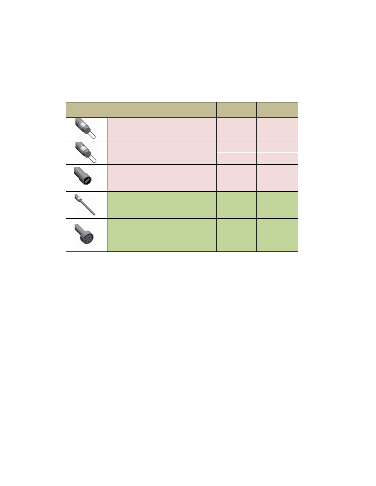
Because they are designed to corrode, ER probes are sacrificial in nature. Each ER probe will have a
finite life that is based on the element thickness. ER probes are available in a number of geometries
and thicknesses designed to suit a wide variety of applications. Table 1 lists the common ER element
options available from Metal Samples and the effective life of each.
Element Type Compatibility Thickness
Probe Life
(Span)
Tubular Loop Compatible 4 2
8 4
Wire Loop Compatible
40 10
80 20
Flush (Small) Compatible
4
2
8 4
20
10
Cylindrical Preferred
10
5
20 10
50
25
Flush (Large) Preferred
5
2.5
10
5
20
10
40 20
Table 1. Standard ER Probe Elements
The MS4500E-HC High Resolution ER Data Logger measures an ER probe utilizing a high-resolution, 16-
bit measurement. This allows the unit to detect much smaller amounts of metal loss, thus
responding faster to corrosion events and upsets. At 16-bit resolution the MS4500E-HC ER Data
Logger can measure metal loss amounts as small as 0.004% of the probe life. For highly sensitive
probes such as the 5-mil large flush shown above, that results in a detection limit of less than one
angstrom.

3
C. Technical Specifications
Model MS4500E-HCHigh Resolution ER Data Logger
Physical Data
Instrument Weight (w/ boot):
1.71 lb. (0.78 kg)
Total Weight w/ Case & Accessories:
6.96 lb. (3.16 kg)
Instrument Dimensions (w/ boot):
8.75"L x 4.54"W x 2.20"D (21.77cm x 11.53cm x 5.59cm)
Instrument Dimensions (w/o boot):
7.50"L x 4.00"W x 2.00"D (19.05cm x 10.16cm x 5.08cm)
Carrying Case Dimensions:
14.50"L x 11.38"W x 5.88"D (36.83cm x 28.89cm x 14.92cm)
Operating Temperature:
-4° to 130°F (-40° to 70°C)
Storage Temperature:
-4° to 158°F (-40° to 85°C)
Operating Humidity Range:
30% - 95%
Performance Data
Measurement Type:
ER measurement using any standard ER Probe Types
Preferred Probe Types: Cylindrical, Flush(Large)
Compatible probe types: Tube Loop, Wire Loop, Flush (Small)
Range:
0 - 25,000 probe life units (displayed as 0.00 to 1000.00 PLU’s in
0.04 increments)
Resolution:
0.004% of Probe Life
Repeatability:
± 0.1% of Full Scale
Cycle Time:
25 Seconds
Electrical Data
Power Requirements:
Two (2) C Type Batteries
Maximum Probe Cable Distance:
200 ft. (61 m)
Download Method:
Directly to USB Flash drive (Certified USB Drive)
Hazardous Location Certifications –IntrinsicSafety
Europe and Worldwide Class1, Zone 0 AEx ia [ia] IIC T4 Ga
(
ATEX and IECEx) MS4500E-HC
‐40°C ≤ Ta ≤ + 70°C
(for use with Xeno Energy XL-145F or Tadiran TL-4920)
Europe and Worldwide II 1 G Ex ia IIC T4 Ga
(
ATEX and IECEx) MS4500E-HC
-40°C ≤ Ta ≤ + 70°C
(for use with Xeno Energy XL-145F or Tadiran TL-4920)
ATEX Certificate No: ITS18ATEX203161X
IECEx Certificate No: IECEx ETL 18.0007X
X – see Special Conditions (page 8)
Included Accessories
Carrying case, Probe Cable (1’ coiled -6’ extended), Meter Prover, Operation Manual, Corrosion Data
Management Software, Protective Boot.

4
II. Start-up and Operation
A. Receiving the MS4500E-HCHigh Resolution ERData Logger
Check the MS4500E-HC High Resolution Data Logger for any shipping damage when it is first received.
When the unit is unpacked, verify that the following items are included:
•Carrying Case
•Data Logger
•Meter Prover
•User’s Manual
•Probe Cable
In theevent of shipping damage, quantity shortage, or missing items, it is recommended that the
event is documented immediately and that digital photographs are taken. Any shortages or missing
items should be reported to Metal Samples immediately. In the event of shipping damage, a claim
should be opened with the responsible carrier.
B. Start-Up
CAUTION: Using this product in any way other than that specified within this manual may impair the
intrinsic safety protection.
ATTENTION : l'utilisation de ce produit de toute autre manière que celle spécifiée dans le présent manuel
peut altérer la protection de sécurité intrinsèque.
Start-up of the MS4500E-HC High Resolution Data Logger involves the following steps:
1. Port Details and Probe Connection
2. Power-Up
3. Setup and Operation
1. Port Details and Probe Connection
Attention: Utilisez Seulement
dans des endroits Sécurisés

5
The MS4500E-HC High Resolution Data Logger is supplied with a probe cable and it can be
connected to the probe whose metal loss value needs to be measured, no additional hardware is
necessary. Connect the probe cable ‘Lemo’ connector end to the data logger probe connector ‘J9’
available on top of the data logger. Connect the other end of the probe cable i.e. probe connector
(MS Connector) to the probe.
2. Power-Up
The unit is supplied with two (2) C type batteries installed. The instrument can bepowered upby
pressing the ‘ON’ button on the Keypad .The Start-upscreen with the Metal Samples logo will appear
on the screen; the start-upscreen confirms the software version currently running andthe SD card
status.
Power On Button
Display Window
1. SELECT PROBE
2. MAKE MEASUREMENT
3. RECALL READINGS
4. DELETE READINGS
5. SET TIME & DATE
6. SET MEASUREMENT TIMER
7. COMMUNICATIONS
8. LANGUAGE / IDIOMA / LINGUAGEM
9. POWER OFF
10. BACKLIGHT ON/OFF

6
a. Safe Area Usage
The MS4500E-HC High Resolution Data Logger is approved for use in hazardous areas, but
can be used in non-hazardous areas as well.
The data transfer from the unit to PC should be done in a safe area. A certified USB isolator/
Barrier should be used between the unit and PC for data transfer.
b. Hazardous Area Usage
CAUTION:This section provides general guidelines for hazardous areausage. However,
regardless of anythingstated here, the MS4500E-HC High Resolution Data Logger must be used
in full compliance with the control drawing located in Appendix A and all of the local area
requirements. The entity parameters ofthe unitaregiven below.
ATTENTION :Cette section fount des directives générales pour l’utilisation enzone dangereuse
Toutefois, et indépendamment de toute déclaration faite ici, L’enregistreur de données de
haute résolution MS4500E-HC doit être utilise en pleine conformité avec le schéma de
contrôle donne enpage 20 et avec toutes les exigences du locale zone dangereuse.
J9-USB Port J8 – Mini USB Port Entity Parameters):
Uo= 4.94V Uo= 4.94V
Io= 0.332A Io= 0.215A
Po= 0.410 W Po= 0.322 W
Co= 1.0 uF
Lo= 100 uH
SPECIAL CONDITIONS
•Connection of the equipment to the ET1867 USB barrier (or any other certified barrier used with the
equipment) may only be made whilst both the barrier and the equipment are located in the non-
hazardous area.
•External non-metallic materials utilize a conductive coating to prevent the risk of electrostatic charging.
The equipment shall be removed from service if damage to this coating is observed. Refer to the
manufacturer’s instruction manual for further information on the durability and any chemical vulnerability
of this coating.
CONDITIONS PARTICULIERES
• La connexion de l'équipement à la barrière USB ET1867 (ou toute autre barrière certifiée
utilisée avec l'équipement) ne doit être effectuée que lorsque la barrière et l'équipement sont
situés dans une zone non dangereuse.
• Les matériaux externes non métalliques utilisent un revêtement conducteur pour éviter le
risque de charge électrostatique. L'équipement doit être retiré du service si des dommages à ce
revêtement sont observés. Reportez-vous au manuel d'instructions du fabricant pour plus
d'informations sur la durabilité et la vulnérabilité chimique de ce revêtement.

7
CAUTION
1. Mini USB port to transfer the data from the Data Logger to PC allowed only in safe area
through certified USB barrier.
2. Connection of the equipment to the Metal Samples # ET1867 USB barrier (or any other
certified barrier used with the equipment) may only be made whilst both the barrier and the
equipment are located in the non-hazardous area.
3. Only Certified USB flash drives are allowed to use in Hazardous locations.
4. Conductive coating utilized on the equipment is permanently static dissipative and humidity
independent, no further maintenance is necessary. The unit needs to be returned to
manufacturer if any damages/scratches noticed on the outer surface of the equipment.
* DO NOT USE CHEMICAL SOLVENTS TO CLEAN THE OUTER SUFRACE OF THE EQUIPMENT OR BOOT.
ATTENTION :
1. Mini port USB pour transférer les données de l'enregistreur de données au PC autorisé
uniquement dans une zone sûre grâce à une barrière USB certifiée.
2. Connexion de l'équipement aux échantillons métalliques # ET1867 La barrière USB (ou toute
autre barrière certifiée utilisée avec l'équipement) ne peut être fabriquée que si la barrière
et l'équipement sont situés dans une zone non dangereuse.
3. Seuls les lecteurs flash USB certifiés sont autorisés à utiliser dans des endroits dangereux.
4. Le revêtement conducteur utilisé sur l'équipement est en permanence antistatique et
indépendant de l'humidité, aucun entretien supplémentaire n'est nécessaire. L'unité doit
être retournée au fabricant si des dommages / rayures ont été constatés sur la surface
extérieure de l'équipement.
* N'UTILISEZ PAS DE SOLVANTS CHIMIQUES POUR NETTOYER LE SUFRACE EXTERNE DE L'ÉQUIPEMENT
OU DE LA BOTTE.
8
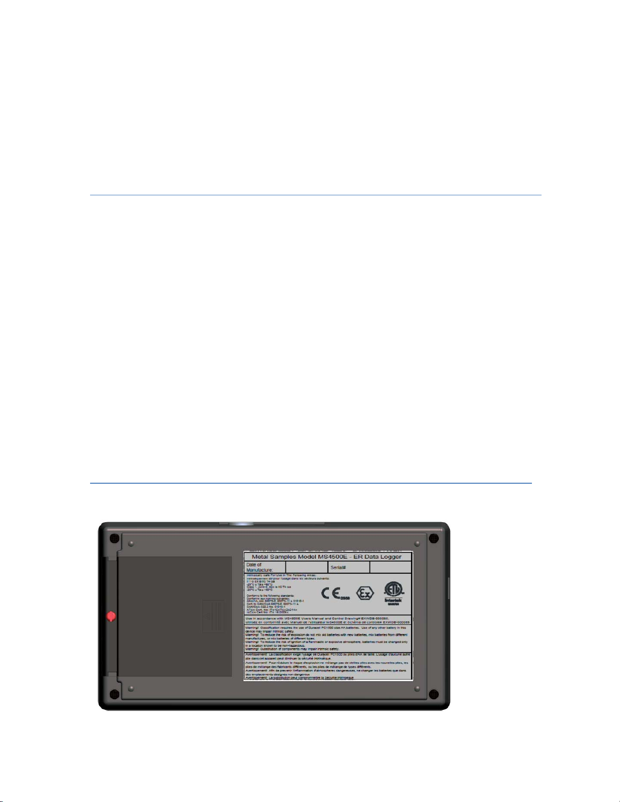
c. Battery Replacement
The battery compartment is located on the back of the instrument. You must first remove it to access
the battery compartment.
To replace the batteries, first loosen and remove the cover screw, then remove the battery cover to
expose the batteries. Remove the old batteries and replace them with two new3.6V ‘C’ size
batteries for MS4500-HC,being sure tofollow the polarity (+/-) symbols in the battery compartment.
Replace the battery cover and cover screw.
WARNING:
•Do not mix old and new batteries.
•Do not mix batteries of different types (such as alkaline and lithium.)
•MS4500E-HC
Xeno XL-145F / Tadiran TL4920 battery is required for intrinsic safety.
•The cover screw is used to prevent unauthorized tampering of the batteries and is required to ensure
intrinsic safety.
•Do not over-tighten the cover screw, as this may damage the instrument case.
ATTENTION:
•Avertissement ! Ne mélangez pas des piles neuves et usées.
•Avertissement ! Ne mélangez pas des piles de types différents (telles que des piles alcalines etdes
piles lithium.)
•Avertissement ! MS4500E-HC
La pile Xeno XL-145F / Tadiran TL4920 est requise pour la
sécurité intrinsèque
•Avertissement ! La vis du couvercle est utilisé pour éviter toute manipulation non autorisée des
batteries, et est nécessaire pour assurer la sécurité intrinsèque.
•Avertissement ! Ne pas trop serrer les vis du couvercle, pour ne pas endommager le boîtier de
l'instrument

9
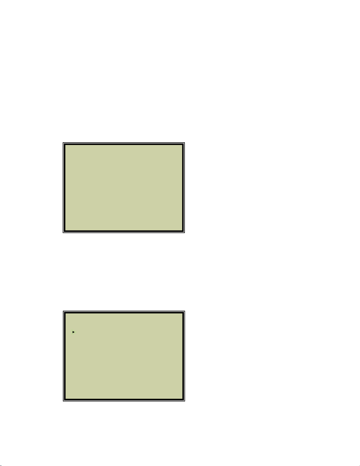
3. Setup and Operation
MAIN MENU
The MS4500E-HCallows you tomeasure metal loss and corrosion rate. Review this section which
describes the functions that display on the Main Menu:
Select the functions by using the up or down arrow and pressing ENTER or directly selecting the number
using the keypad and press ENTER. Pressing ‘EXIT’ will return the selection to the first item of the Main
Menu.
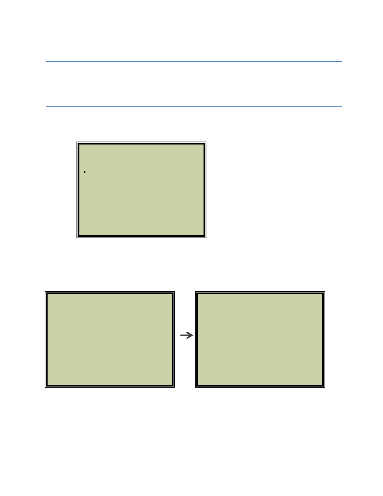
a. Select Probe
The display will show as below if you select ‘SELECT PROBE’ menu from the main menu. You can enter a
new probe, delete a probe, or select an existing probe from this section.
1. SELECT PROBE
2. MAKE MEASUREMENT
3. RECALL READINGS
4. DELETE READINGS
5. SET TIME & DATE
6. SET MEASUREMENT TIMER
7. COMMUNICATIONS
8. LANGUAGE / IDIOMA / LINGUAGEM
9. POWER OFF
10. BACKLIGHT ON/OFF
ENTER NEW PROBE
DELETE EXISTING PROBE
1000: WIRE LOOP PL:10.0
2500: CYLINDRICAL PL:10.0
2500: CYLINDRICAL PL:10.0
0434: TUBE LOOP PL:10.0
PRESS ENTER TO SELECT
10
ENTER NEW PROBE - To enter the ID of a new probe, select ‘ENTER NEW PROBE’; the next screen
allows you to enter the ID number and the type.
1. Enter the Probe ID using the number keys. (Use the Up/Down arrows to scroll between
alphanumeric characters. Use the Right/Left arrows to advance to the next character or go back to
the previous character.) When a 4-digit Probe ID is entered the cursor automatically advances to
the Probe Type field.
2. Use the Up/Down arrows to select the Probe Type. Use the Right arrow to advance to the Probe
Life field.
3. Enter the Probe Life using the number keys.
4. Press ENTER.
SELECT EXISTING PROBE
To assist you with selecting a probe ID, the screen displays a list of all probe IDs currently in memory.
Select from the list of probes in memory the one for which you wish to run a function (Make
Measurement, Recall Readings and Delete Readings).
oPress the arrow key to select a probe ID.
oPress ENTER.
ENTER NEW PROBE
DELETE EXISTING PROBE
1000: WIRE LOOP PL:10.0
2500: CYLINDRICAL PL:10.0
2500: CYLINDRICAL PL:10.0
0434: TUBE LOOP PL:10.0
PRESS ENTER TO SELECT
PROBE ID: 5385
PROBE TYPE: WIRE 40
PROBE LIFE: 10.0
PRESS UP / DOWN ARROW TO CHANGE

11
DELETE EXISTING PROBE
It is occasionally necessary to remove the ID of a probe from memory, for example:
oWhen the memory bank is full
oWhen a probe is no longer used
To delete the ID of a probe in memory, select DELETE EXISTING PROBE.
1. Enter the probe ID - use the number keys (press the DOWN arrow if you make an error).
2. Press the UP arrow when you’ve entered the correct ID number.
The instrument will confirm your choice of probe ID before deleting it from memory.
DELETE PROBE
PROBE ID: 1000
USE UP / DOWN ARROW TO CHANGE
12
b. Make Measurement
Select a probe before you run the function
In order for you to run ‘MAKE MEASUREMENT’ ‘RECALL READINGS’ & ‘DELETE READINGS’,
you must have already selected a probe from memory. See ‘SELECT PROBE’ from the Main
menus (page 8).
To take measurement from probes in memory, select ‘MAKE MEASUREMENT’ menu from the
Main Menu:
The next screen displays the probe ID that you selected earlier from the Main Menu item
‘SELECT PROBE ’.
Press ‘ENT’ button to start measuring the probe value. During measurement ‘MEASURING.. ‘
message displays on the screen. On completion of measurement the display shows the
probe reading.
Press ‘ENT’ button to save the reading. Press ‘Up’ Arrow to re-measure the probe again.
1. SELECT PROBE
2. MAKE MEASUREMENT
3. RECALL READINGS
4. DELETE READINGS
5. SET TIME & DATE
6. SET MEASUREMENT TIMER
7. COMMUNICATIONS
8. LANGUAGE / IDIOMA / LINGUAGEM
9. POWER OFF
10. BACKLIGHT ON/OFF
PROBE ID:1234
TUBE
PRESS ENTER TO START
PROBE ID:1234
PREVIOUS READING : 860.61
PROBE CHECK : 808.69
READING: 860.60
MEASURING…..
PRESS UP ARROW TO REMEASURE
PRESS ENTER TO SAVE

13
c. Recall Readings
Select ‘RECALL READINGS’ to look at data from different dates.
Select the probe if it is not already selected to look in to the readings by using up/down
arrows and press ‘ENT’ button. The readings of the selected probe will be displayed in the
next screen.
Press ‘ENT’ button on the keypad to plot the graph of the selected probe. The graph will be
displayed on the next screen with metal loss value and corrosion rate.
ENTER NEW PROBE
DELETE EXISTING PROBE
1000: WIRE LOOP PL:10.0
2500: CYLINDRICAL PL:10.0
2500: CYLINDRICAL PL:10.0
0434: TUBE LOOP PL:10.0
PRESS ENTER TO SELECT
PROBE ID:1000
RDG# READING DATE(M/D/Y) TIME CHECK
8 859.60 04/24/15 18:45 809 7
759.59 04/24/15 18:45 704 6
841.60 04/24/15 18:45 705
5 459.00 04/24/15 18:45 809
4 118.00 04/24/15 18:45 704
3 434.00 04/24/15 18:45 705
2 118.00 04/24/15 18:45 809
1 456.54 04/24/15 18:45 809
PROBE ID:1000
P1000 L
R04/01/15
ORDG : 860.04
BML : 8.60
ER
04/27/15
RDG : 860.32
500 ML : 8.60
COR RATE:
U0.05 MPY
N
I
T
S0 124 248 372 496

14
d. Delete Readings
Select ‘DELETE READINGS’ from Main Menu to erase a reading from memory.
Periodically delete readings to create more free storage area in memory.
Select the probe from which the readings need to be deleted by using up/down arrows and
press ‘ENT’ button. The readings of the selected probe will be displayed in the next screen.
Select the probe reading (RDG#) number which needs to be deleted by using up/down arrows
and press ‘ENT’ button. The selected probe reading will be deleted permanently from the
instrument memory.
ENTER NEW PROBE
DELETE EXISTING PROBE
1000: WIRE LOOP PL:10.0
2500: CYLINDRICAL PL:10.0
2500: CYLINDRICAL PL:10.0
0434: TUBE LOOP PL:10.0
PRESS ENTER TO SELECT
PROBE ID:1000
RDG# READING DATE(M/D/Y) TIME CHECK
8 859.60 04/24/15 18:45 809
7 759.59 04/24/15 18:45 704
6 841.60 04/24/15 18:45 705
5 459.00 04/24/15 18:45 809
4 118.00 04/24/15 18:45 704
3 434.00 04/24/15 18:45 705
2 118.00 04/24/15 18:45 809
1 456.54 04/24/15 18:45 809

15
e. Set Time & Date
Select ‘SET TIME & DATE’ from Main Menu to set the internal clock of the MS4500E-HC
Data Logger. In order for information in memory to be useful and accurate, be sure
the time and date are accurate.
CAUTION: The Time and Date areset at the factory, but may need to be adjusted to your
time zone. Also, if you try to change the Date orTime and it conflicts with stored
information, the MS4500E-HC will display N/A.
ATTENTION : l'heure et la date sont définies à l'usine, mais ils peuvent être ajustées à votre
fuseau horaire. Aussi, si vous essayez de changer la date ou l'heure et que ce ci conflit avec
l'information mémorisée, le MS4500E-HCaffichera N/A.
Use the numbers on the keypad and the arrow keys to make changes to the time and date.
Press ‘ENT’ button on the keypad to confirm your changes and return to the Main Menu , or
Press ‘EXIT’ button to discard the changes.
DATE (MM / DD / YY):
04 / 27 / 15
TIME (HH:MM):
03: 42 PM
USE LEFT / RIGHT ARROW TO SELECT
USE UP / DOWN ARROW TO CHANGE
PRESS ENTER TO SAVE

16
f. Set Measurement Timer
Select ‘SET MEASUREMENT TIMER’fromMain Menu to set automatic probe reading at
set intervals. The MS4500E-HCData Logger periodically wakes upandtakes the
measurement and stores the reading.
Select a probe before you run the function
In order for you to run MAKE MEASUREMENT, you must have already selected a probe
from memory. See Select Probe ID from the Main menus (see page 8).
If probe is not selected earlier, select the probe from the display. Use Up/Down arrow
keys to select the probe and press ‘ENT’ button.
Use Right/Left arrow keys to turn on/off the data logging. Use Up/Down arrow to
change data logging interval. Minimum can be set as 1 Hours and maximum can be set
as 99 Days. The unit takes the reading once per the set interval.
ENTER NEW PROBE
DELETE EXISTING PROBE
1000: WIRE LOOP PL:10.0
2500: CYLINDRICAL PL:10.0
2500: CYLINDRICAL PL:10.0
0434: TUBE LOOP PL:10.0
PRESS ENTER TO SELECT
DATA LOGGING INTERVAL SETUP
PROBE ID : 2500
SELECT DATA LOGGING INTERVAL:
ONCE EVERY 1 HOURS
LOGGING OFF
RIGHT / LEFT ARROW TO TURN ON/OFF
UP/DOWN ARROW TO CHANGE INTERVAL
PRESS ENTER TO SAVE
17
g. Communications
The MS4500E-HCData Logger has the ability to store readings as they are taken.
These readings can later be transferred to your PC via USB port. To transfer data to a
PC it is necessary to install the Corrosion Data Management Software (included).
Todownloaddatafrom aninstrument:
•
Connect the instrument to an available PC USB port .
•
Turn theMS4500E-HCon.
•
RuntheCorrosionDataManagementSoftware
•
Open the Instrument DownloadCenter
•
Selecttheserial portandinstrument
•
Click the Download button (ensure that Part Status toggles to “On”).
•
Select ‘COMMUNICATIONS’ menu from the Main Menu of the instrument.
•
Select ’TRANSFER ALL’ or Select the Probe data you wish to download.
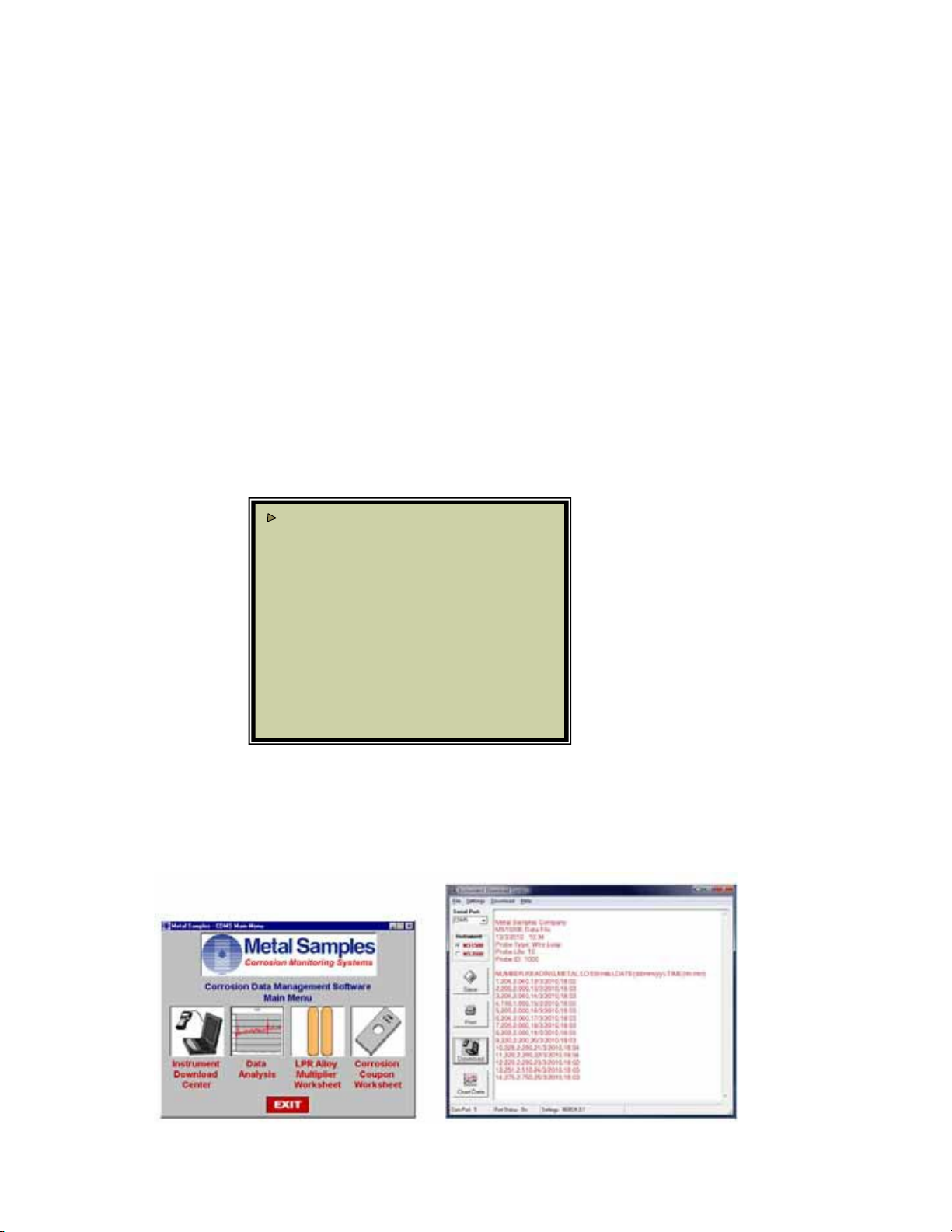
Datawillbegintotransferfromtheinstrument tothe PC,and will appear in the datawindowofthe
Instrument DownloadCenter as shown below. If the data appears garbled, the wrong instrument
type has been selected. Select another instrumenttype and try again.
TRANSFER ALL
1001: WIRE LOOP
PRESS ENTER TO TRANSFER

18
If data does not appear in the data window at all, verify that:
•The instrument is connected to a valid serial or USB port
•Allcablesare securelyconnected
•Themessage “Port Status: On” appears in the status bar
•There are no errorsontheinstrument
•If using a USB adapter, ensure that the device drivers have beeninstalled.
Selecting a Serial Port
When the MS4500E-HCis connected tothe USBport it will appear as a virtual COM port. Use
the Serial Port selection box to select the virtual COM portnumber. If theCOM port number is
unknown,itcan be found inWindows Device Manager under“Ports (COM & LPT)”.
Selecting an Instrument
Use the Instrument option box to select the model of Metal Samples instrumentbeingdownloaded.
Thissetstheappropriatecommunication parameters, whichwill be displayedinthestatus bar at the
bottom of the window (“9600,N,8,1” for an MS1500, “2400,N,8,1” for an MS3500).
Downloading Data
To toggle the selected port on and off, click the Download button. Togglingthe port onand off
willalso clearthe datawindow.
Once avalid serialportandinstrument have been selected, click the Download button to turn the
port on and enable the computer to receive data. If a valid serial port has been selected, the
status bar at thebottom ofthewindow will display themessage “PortStatus: On”.
If an invalid serial port has been selected, an error message will appear, and thestatus bar will display
themessage “PortStatus: Off”. Ifthis happens, another serialport should be selected.
Saving Data
To save the data in the data window, click the Save button. The data is comma-delimitedASCII text.
It can be saved to a standard text (.txt) file,oritcan be saved to acomma-separated values (.csv)file,
which greatly simplifiestheprocessofimportingthe datainto somespread- sheet programs such as
Excel® or Quattro Pro®.
Printing Data
To print the contents of the data window, clickthe Print button. Aprint dialog boxwillbedisplayedto
allowprinter selection andsetup.
Charting Data
To chart the contents of the data window, click theChart Data button. If the data has not yet been
saved, the user will be prompted to do so before thecharting process begins. Formoreinformation
oncharting data, see the DataAnalysis section.
Table of contents
Other Metal Samples Company Data Logger manuals

Popular Data Logger manuals by other brands


Grant
Grant Squirrel SQ2010 SERIES Getting started

ICP DAS USA
ICP DAS USA DL-1 S-WF Series user manual

Agrowtek
Agrowtek SXH instruction manual

Omega Engineering
Omega Engineering OM-SQ2020 Series user guide

ADLINK Technology
ADLINK Technology USBDAQ-9100MS user guide

Ahlborn
Ahlborn ALMEMO 2290-8 operating instructions