Ahlborn ALMEMO 2290-8 User manual

Operating Instructions
Data Logger
ALMEMO®2290-8
V2.1
04.12.2003
ALMEMO®2290-8 1

Operating Instructions
Data Logger
ALMEMO®2290-8
For reference with the ALMEMO®Manual
Table of Contents
Page
1 INTRODUCTION 4
1.1 Function Range 4
1.2 Operating Controls 9
2 INITIAL OPERATION 11
3 POWER SUPPLY 12
3.1 Operation with Battery and Rechargeable Battery 12
3.2 External Voltage Supply 13
3.3 Switch On/Off, Reinitialisation 14
3.4 Battery Buffer 14
4. CONNECTION OF THE TRANSDUCERS 15
4.1 Transducers 15
4.2 Measuring Inputs and Additional Channels 15
5 DISPLAY AND KEYBOARD 17
5.1 Display and Function Selection 17
5.2 Keyboard 18
5.3 Data Entry 19
5.4 Keyboard Lock 19
6 SENSOR PROGRAMMING 20
6.1 Selecting the Input Channel 20
6.2 Selecting the Measuring Range 21
6.3 Changing the Dimension 24
6.4 Limit Values 24
2 ALMEMO®2290-8
Table of Contents

Page
6.5 Correction Values 25
6.6 Scaling, Decimal Point Setting 26
6.7 Locking the Programming of the Sensor 27
7 MEASUREMENT 27
7.1 Continuous Measurement of a Measuring Point 28
7.1.1 Selecting the Measuring Point 28
7.1.2 Memory for Peak Values 29
7.1.3 Averaging 29
7.1.4 Setting the Measured Value to Zero, Zero Point Correction 31
7.1.5 Atmospheric Pressure Compensation 32
7.2 Single Measuring Point Scan 33
7.3 Cyclic Measuring Point Scan 33
7.3.1 Print Cycle, Output Channel, Output Format 34
7.3.2 Measuring Cycle and Memory Activation 35
7.3.3 Conversion Rate, Continuous Measuring Point Scan 35
7.3.4 Time and Date 36
7.3.5 Time and Date of Start, Time and Date of End 36
7.3.6 Start and Stop by Limit Values 37
7.4 Data Memory 38
7.4.1 Data Acquisition 38
7.4.2 Memorry Connector 39
7.4.3 Output of Measuring Data 40
7.5 Numbering Measurements 41
7.6 Sleep Mode 42
8 DIGITAL DATA OUTPUT 43
8.1 Baud Rate, Data Format 43
8.2 Device Address and Networking 44
8.3 Manual Data Output 44
9 ANALOGUE OUTPUT 46
10 TROUBLESHOOTING 47
11 ELECTROMAGNETIC COMPATIBILITY 48
APPENDIX 49
Technical Data 49
Product Overview 49
ALMEMO®2290-8 3
Table of Contents

1. INTRODUCTION
The new data logger ALMEMO®2290-8
Version 5
is an instrument from the
unique product range of measuring devices that are all equipped with the
ALMEMO®connector system, which has been patented by Ahlborn GmbH. The
intelligent ALMEMO®connector provides important advantages with regard to
the connection of sensors and peripherals as all parameters are stored in an
EEPROM within the connector. As a result, the programming that usually has
to be performed for the connection is not required.
All sensors and output modules can be connected to all ALMEMO®measuring
devices in the same way. The operation and programming is identical with all
units. Therefore, all of the ALMEMO®measuring system items listed below are
described, in detail, in a separate ALMEMO®manual that is supplied with every
device:
Detailed description of the ALMEMO®system (manual section 1)
Overview of the device functions and measuring ranges (manual section 2)
All sensors with basic principles, operation, technical data (man. section 3)
The options for connecting existing sensors (manual section 4)
All analogue and digital output modules (manual section 5.1)
The interface module RS232, fiber optics, Centronics (manual section 5.2)
The entire ALMEMO®networking system (manual section 5.3)
All functions and their control via the interface (manual section 6)
A complete interface command list with all print outputs (manual section 7)
These operating instructions only cover features and controls that are specific
for a certain device. As a result, the sections dealing with the system control
via keyboard will only often provide a note referring to a more detailed
description within the manual (manual section x.x.x).
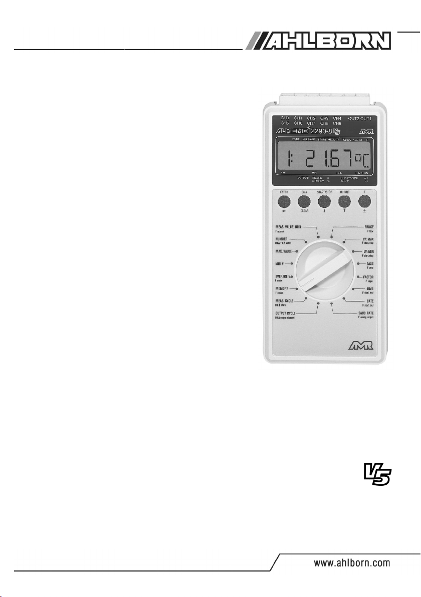
1.1 Function Range
The ALMEMO®2290-8 data logger has five electrically isolated measuring
inputs with up to 20 measuring channels for more than 70 measuring ranges, a
real time clock and a 500kB memory for approximately 100,000 measured
values. Two output sockets allow for connecting any ALMEMO®output
modules, for example, the analogue output, digital interface, trigger input or
alarm contacts. Several devices can be networked by a simple connection
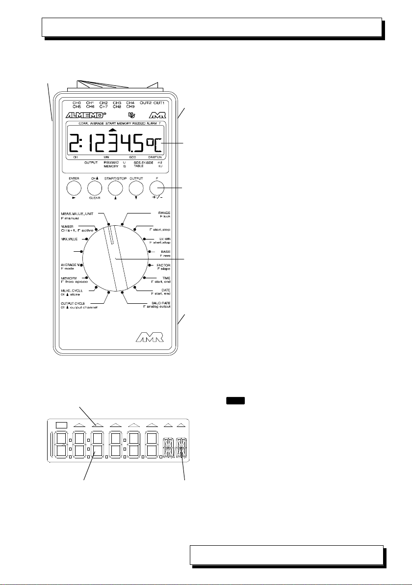
between the devices. For easy operation it is equipped with a rotary switch,
keyboard and an 8½ digit LCD display.
SENSOR PROGRAMMING
The measuring channels are automatically programmed by the ALMEMO®
connectors of the sensors. However, the user can easily complete or modify
the programming via keyboard or via interface.
4 ALMEMO®2290-8
Introduction

Measuring Ranges
There are corresponding measuring ranges for sensors with a non-linear
characteristic such as 10 thermocouple types, Ntc and Pt100 sensors, infrared
sensors, and flow sensors (rotating vanes, thermoanemometers, pitot tubes).
Humidity sensors are available with function channels that also calculate
humidity data such as dew point, mixture ratio, vapour pressure and enthalpy.
Even complex chemical sensors can be used. The acquisition of measured
data from other sensors is easily possible by using voltage, current and
resistance ranges with individual scaling in the connector. Existing sensors can
be used without problems. Only the corresponding ALMEMO®connector has to
be connected using its terminals. Furthermore, there are adapter connectors
with an own microcontroller for digital signals and for measuring frequencies
and pulses. This way, nearly all sensors can be connected to any ALMEMO®
measuring instrument and are interchangeable without requiring any settings.
Function Channels
Maximum, minimum, average values and differences of certain measuring
junctions can be programmed as function channels and can be processed and
printed like normal measuring junctions. Furthermore, function channels for
special measuring tasks are provided to determine temperature coefficient
Q/∆t and wet bulb globe temperatures.
Dimension
The 2 digit dimension can be altered for each measuring channel so that the
display and the printout will always indicate the correct dimension, for example
when a transmitter is connected. The conversion from °C to °F is automatically
performed according to the dimension.
Name of Measured Values
Sensors can be identified by a 10 digit alphanumeric designation. It is entered
via the interface and appears on the printout or display if the evaluation is done
via PC.
Correction of Measured Values
For correcting measured values a zero point and slope (gain) correction can be
applied to the measured value of each measuring channel. This also allows for
sensors to be interchanged that usually, at first, require an adjustment
(expansion, force, pH). The zero point and the slope (gain) correction are
virtually performed by the push of a button.
Scaling
The base value and the factor allow for a further scaling of the corrected
measured value of each measuring channel for zero point and slope (gain).
The decimal point position can be set by the exponent. By setting to zero and
entering the nominal value the scaling values can be automatically calculated.
ALMEMO®2290-8 5
Functions

Limit Values and Alarm
Two limit values (1 max and 1 min) can be set for each measuring channel. An
alarm value printout can be performed if a limit value is exceeded and, by
means of relay output modules, alarm contacts are provided that can be
individually allocated to limit values. As a standard, the hysteresis is set to 10
digits, however, it can also be adjusted. Furthermore, limit value exceeding can
also be used to start or stop a data logging.
Sensor Locking
All sensor data stored in the EEPROM of the connector can be protected
against undesired access by means of a graded locking function.
MEASUREMENT
A total of up to 20 measuring channels are available for 5 transducers, i.e. it is
also possible to evaluate double sensors, individually scaled sensors, or
sensors with function channels. The measuring channels can be successively
selected forwards or backwards via keyboard. The selected measuring point
can be scanned with a conversion rate of 2.5 or 10 measurements/second.
The measured value is calculated and indicated on the display or, if available,
provided on the analogue output.
Measured Value
A continuous presentation of measuring data from the selected measuring
point is provided and also includes automatic zero point correction and optional
correction of the measured value or new scaling.
A sensor breakage condition is, with most sensors, automatically detected
(exception: connectors with shunts, dividers or additional electronics).
Analogue Output and Scaling
By means of analogue start and analogue end the indicated measured value
can be scaled so that the resulting measuring range covers the full analogue
output range (2V, 10V or 20mA).
Measuring Functions
Special measuring functions are required for some sensors in order to achieve
an optimal acquisition of measuring data. The cold junction compensation is
available for thermocouples, a temperature compensation for dynamic
pressure and pH and conductivity probes, and an atmospheric air pressure
compensation for humidity sensors, dynamic pressure sensors and O2
sensors. With infrared sensors the parameters zero point and slope correction
are used for background temperature and emissivity factor.
Maximum and Minimum Value
Each measurement involves an acquisition and storing of the maximum and
minimum value. These values can be displayed, printed or cleared.
6 ALMEMO®2290-8
Functions

Average Value of a Channel
A manual averaging over a particular period or over single measurements is
available for the selected channel.
PROCESS FLOW PROGRAMMING
A cyclic measuring point scan with a time-based process flow control is
required to register the measuring data of all connected sensors. For this
purpose, the real time clock, the print cycle and the measuring cycle are
available and, if fast processing is required, the conversion rate is available.
The measurement can be started and stopped by using the keyboard, the
interface, an external trigger signal, the real time clock or an exceeding of limit
values.
Time and Date
The real time clock with date function or the pure measuring time are used for
an accurate recording of any measurement. Start and end time/date can be
programmed in order to start or stop a measurement.
Print Cycle
The print cycle is programmable between 1s and 59h/59min/59s and provides
a cyclic output of measured values to the interfaces or memories and also
provides a cyclic averaging.
Print Cycle Factor
If necessary, the print cycle factor allows for limiting the data output of
particular channels so that an excessive data flow can be limited, especially
during data storage.
Measuring Cycle
The measuring cycle, also programmable between 1s and 59h/59min/59s, is
for a cyclic scanning with a display of all measured values, limit value
monitoring including alarm message and output of alarm values, averaging
and, if necessary, a storage of measured values.
Average Value over Measuring Point Scans
The measured values that result from scanning the measuring junctions can
be averaged as desired either over the total measuring time or over the print
cycle time. Function channels are provided for a cyclic output of average
values.
Conversion Rate
With ALMEMO®
V5
devices, all measuring points can be continuously
scanned with the conversion rate (2.5 or 10 meas./s). It is possible to store all
measured values in the memory and/or to perform an output via the interface.
ALMEMO®2290-8 7
Functions

Storage of Measured Values
During the measuring or print cycle, all measured values or alarm values can
be manually or automatically stored in a buffered RAM. The memory capacity
is, as standard, 500kB, which allows up to 100,000 measured values. The
memory organisation can be configured as linear or ring memory. Deductible
ALMEMO®memory connectors are alternative usably. The output can be
optionally performed via interface, analogue output or display. It is possible to
select a certain time interval, number or alarm value.
Numbering of Measurements
Single scans or entire series of measurements can be identified and selectively
read out from the memory.
Control Outputs
The interface allows to individually trigger up to four output relays and one
analogue output.
Keyboard Lock
The keyboard operation can be locked with a password.
Output
All measuring and programming data is accessible by means of the LCD
display. RS232, RS422, Ethernet and a Centronics interface are available by
using different interface cables. All data logs, measured values and
programmed parameters can be provided as output to any peripheral
equipment. The output of measuring data can be selected in list format,
columns or spreadsheet format. Files in spreadsheet format can be processed
by each spreadsheet software. The print header can be programmed
specifically to the company or application.
Networking
All ALMEMO®devices can be addressed and can be easily networked by a
simple connection with network cables or network junctions for longer
distances.
Software
The AMR-Control software, which allows for the entire programming of the
sensors, the configuration of the measuring instrument and the read-out of the
data memory is supplied with each ALMEMO®manual. The integrated terminal
also allows for online measurements. The WINDOWS®software packages,
Win-Control and DATA-Control, are available for data acquisition of networked
devices, graphical presentation and complex data processing.
8 ALMEMO®2290-8
Functions

1.2 Operating Controls
(1) ON/OFF switch
up SLEEP
centre ON
down OFF
(2) Measuring Inputs CH0 to CH4
CH0 to CH4 for all ALMEMO®sensor
CH5 to CH19additional channels
(3) Output Sockets OUT1, OUT2
OUT1 Interface RS232 (ZA 1909-DK5)
Fiber Optics RS232 (ZA 1909-DKL)
Ethernet (ZA 1945-DK)
Centronics (ZA 1936-DK)
RS 422 (ZA 5099-NVB)
Analogue Output 1 (ZA 1601-RK)
OUT2 Network Cable (ZA1999-NK5)
Memory connector (ZA1904-SS)
Trigger Input (ZA 1000-ET/EK)
Relay Outputs (ZA 1000-EGK)
Analogue Output 2 (ZA 1601-RK)
(4) DC Socket
Mains Adapter (ZB 2290-NA, 12V, 200mA)
Cable, electr. isol. (ZB 2290-UK, 10-30V)
(5) LCD Display
(6) Function Keys
(7) Function Selector Switch
(8) Battery Box (back of unit)
Alkaline mangan. battery 9V (6F22)
Space for spare battery
(5) LCD Display
(a) Symbols for operating modes
U battery < 7 V
BAT
▲ CORR Correction of meas. value
▲ AVERAGE Averaging
▲ START Measuring point scan
▲ MEMORY Memory receive, output
▲ RS232C Output of meas. value
▲ ALARM Exceeding of limit value
▲ F Additional function
(b) 6½ x 7 segment display for:
Meas. point, meas. value, meas. range,
meas. and progr. values, cycles, time,
date
(c) 2 x 16 segment display for:
Dimension of the measured value,
Abbrev. for additional functions
ALMEMO®2290-8 9
(1) (2) (3)
(4)
(5)
(6)
(7)
(8)
LV : M A X
MIN. V.
2290-8
Operating Controls
23
BAT
CORR AVERAGE START RS232CMEMORY ALARM F
a
bc

(2) FUNCTION KEYS
ENTER CH START/STOP OUTPUT F
CLEAR
±
ENTER, ±, ▲▼, for entering programming values
▲
ENTER, CLEAR clear data, set meas. value to zero
ENTER, ±calibrate measured value
M ▲select measuring point
START/STOP cyclic measuring point scan
OUTPUT data output to interface
Fsingle measuring point scan
select additional functions
(3) FUNCTION SELECTOR SWITCH
Function Key Additional functions Abbrev.
MEAS. VALUE, UNIT F single measuring point scan
NUMBER F deactivate (A)
CH▲increase (A)
MAX VALUE F analogue output-end (AE)
MIN VALUE F analogue output-start (AS)
AVERAGE V F averaging mode (AM)
F,F number of aver. values C
RANGE F locking mode LM
F,F locking code LC
LV MAX F action Hi start/stop AH
LV MIN F action Lo start/stop AL
BASE F zero point correction ZC
F ambient temperature AT *
FACTOR, ± Exponent F slope (gain) correction SC
F emissivity factor EF *
MEMORY F free memory FR
MEAS CYCLE CH▲store on/off S
F conversion rate CR
PRINT CYCLE CH▲output channel / format U
F device address A
TIME F start time S
F,F end time E
DATE F start date S
F,F end date E
BAUD RATE F atmospheric pressure mb
* infrared sensors only
10 ALMEMO®2290-8
Operating Controls

2. INITIAL OPERATION
1. Connect transducers in the correct order to the sockets CH0 to CH4, see 4.
2. Ensure power supply with 9V battery or mains adapter, see 3.1, 3.2.
3. For switching on move the slide switch (1) on the left side of the unit to the
centre position, see 3.3.
4. For displaying the measured values,
select function MEAS. VALUE by using the rotary switch (7),
use key CH▲to select the measuring channels, read meas. values, see 7.1.
5. For storing the measured values, see 7.4.
Use function MEMORY and keys ENTER, CLEAR to clear the memory.
Use MEAS. CYCLE and key CH▲to activate the memory ´S´, see 7.3.2.
Single measuring point scan by key Fwithin function MEAS.VALUE, see 7.2.
Enter measuring cycle for cyclic storing, see 7.3.2.
Enter time and date, as required, see 7.3.4.
Enter time and date of start or end of a measurement as required, see 7.3.5.
Use key START/STOP to start and stop a cyclic storing, see 7.3.
Output of memory data to printer or computer
Connect peripheral device via interface cable to socket A1, see manual 5.2.
Set 9600 bd, 8 data bits, 1 stop bit, no parity at peripheral device, see 8.1.
Use key CH▲within function OUTPUT CYCLE to set the output channel ´ U´
and, possibly, the format columns ´nU´ or spreadsheet/table ´tU´, see 7.3.1.
Use key OUTPUT within function MEMORY to output meas.values, see 7.4.2.
6. Cyclic output of measured values to printer or computer
Connect peripheral device via interface cable to socket A1, see manual 5.2.
Set 9600 bd, 8 data bits, 1 stop bit, no parity at peripheral device, see 8.1.
Enter time and date, as required, see 7.3.4.
Program the print cycle within function OUTPUT CYCLE,
use key CH▲ to set the output channel ´ U´ and, if required,
the output format columns ´nU´ or spreadsheet/table ´tU´, see 7.3.1.
Use key START/STOP to start and stop the cyclic meas. point scan, see 7.3.
7. Monitoring of limit values
Enter limit values, see 6.4.
Program measuring cycle, see 7.3.2.
Connect alarm device with alarm module to socket OUT2,
see man. 5.1.2/5.1.3.
For an alarm print use key CH▲within function OUTPUT CYCLE to activate
the output channel ´ U´, see 7.3.1.
Use key START/STOP to start and stop the cyclic meas. point scan, see 7.3.
8. Evaluation of the measurement
Display max and min values within function MAX or MIN VALUE, see 7.1.2.
ALMEMO®2290-8 11
Initial Operation

3. POWER SUPPLY
The following options are available for the power supply of the instrument:
9V battery IEC 6 F22 ZB 2000-B9
9V rechargeable battery,
as above with charger unit integrated in plug ZB 2000-A9, ZB 2000-LS
Mains adapter 12V/200mA ZB 2290-NA
External power supply, connecting cable ZB 2290-UK
Our product line includes corresponding accessories.
3.1 Operation with Battery and Rechargeable Battery
Only use type IEC 6 F22 alkaline manganese batteries. At a current
consumption of approximately 10mA, they last for an operating time of 35
hours. The operating time will be shortened if sensors or modules are
connected that consume additional current.
Inserting Batteries:
The battery box (8) is located at the underside of
the instrument.
1. Press the area that is marked with the arrow and,
at the same time, pull as marked by the arrow, as
illustrated left.
2. Use the connector clip to connect the battery. The
connector shape prevents from confusing the
poles.
3. Use the second battery box to store a spare
battery.
Battery Control:
If the battery warning symbol is illuminated in the
display the battery will still operate for approx. 5 hours
(supply voltage <7V).
If the battery voltage drops below 6 volts ´ LobAt ´ will
be indicated on the display.
The battery should be immediately removed. Leakage
of the battery and damage to the instrument can then
be avoided.
The actual battery voltage can be accurately monitored with an
own measuring channel Ubat and the remaining battery life can
be estimated accordingly.
12 ALMEMO®2290-8
Power Supply

Tips regarding correct handling of batteries:
Do not leave used batteries in the instrument!
Remove batteries from the instrument if it is not used for a long period.
Risk to health and instrument failure can result from leaking batteries!
Therefore, only use leak-proof batteries.
Used batteries are hazardous waste and must be disposed in an
environmentally friendly way! Return them to the dealer or dispose of
them in a battery storage container.
Operation with rechargeable batteries:
Rechargeable batteries can be used instead of normal batteries. Due to their
smaller capacity of 110mAh they only reach an operating time of 11 hours. The
operating time will be shortened if sensors or modules are connected that
consume additional current. It is recommended to use the 9V rechargeable
battery with plug-integrated charger unit ZB 2000 LS, which is included in the
range of accessories.
Tips regarding correct handling of rechargeable batteries:
The rechargeable batteries supplied are not charged when delivered!
If NiCD cells are only partly discharged, the full capacity cannot be
reached by a normal recharging.
Therefore, use the instrument until the rechargeable batteries are
completely discharged.
Completely recharge the rechargeable batteries afterwards.
As a result, the life of the rechargeable batteries is significantly
increased.
Completely recharged batteries will slowly discharge during storage.
3.2 External Voltage Supply
For an external voltage supply the connector socket (4) is located at the right
side of the device. The range of accessories includes the mains adapter ZB
2290-NA (12V/200mA). However, any other DC voltage source (7 to 13V) can
also be used. The connection is performed by a low-voltage connector (NES1
according to DIN 42323, centre pin to negative).
The electrically isolated supply cable ZB 2290-UK must be used if an
electrical isolation between power supply and transducers is required or if a
larger input voltage range 10...30V is required. It allows to operate the
measuring instrument with 12V or 24V mains supply.
If a battery is used in addition it will take over the power supply
if the voltage drops under 9V.
ALMEMO®2290-8 13
Power Supply

3.3 Switch On/Off, Reinitialisation
The ON/OFF switch (1) on the left side of the device has three positions:
up: ON sleep mode
centre: ON normal mode
down: OFF
To switch-on the active measuring mode the slide switch (1) on the left side
must be moved one step upwards (centre position).
The second, top position is meant for a power-saving operation when the
device is temporarily switched off and afterwards by the real time clock is
regularly, in cycles, switched on again for measuring point scans. An automatic
query cycle (for at least 2 minutes) must be started (see 7.6) for switching to
the sleep mode for long term monitoring.
The device is switched off when the slide switch is moved to the lower
position. However, the real time clock continues its operation and all stored
values will be maintained (see 3.4).
If the device shows an irregular behaviour due to interference influences (e.g.
electrostatical charging or wrong connection of peripheral devices) or if
incorrect programming must be avoided, the device can be completely
reinitialised.
The reset can be achieved if the key CLEAR is pressed during switch-on. All
internal data such as max, min and average values, and the data memory will
be cleared. Furthermore, cycles, time, date and device address are set to zero
and the conversion rate and atmospheric pressure will be set to the standard
values. However, the device configuration and the sensor programming within
the ALMEMO®connectors will not be affected by the reset.
3.4 Battery Buffer
A lithium battery (3V) is integrated in the device and ensures an uninterrupted
power supply for the real time clock and memory. As a result, the time and
date and all stored data will be maintained if the 9V battery is replaced or if the
power fails during operation with mains supply.
14 ALMEMO®2290-8
Power Supply

4. CONNECTION OF THE TRANSDUCERS
Any ALMEMO®sensors can be connected to the ALMEMO®input sockets CH0
to CH4 of the measuring instrument (2). For connecting existing sensors it is
only necessary to connect a corresponding ALMEMO®connector.
4.1 Transducers
A detailed description of the comprehensive ALMEMO®sensor range (see
manual section 3) and the connection of existing sensors (see manual section
4) to the ALMEMO®instruments are provided in the ALMEMO®manual. All
standard sensors with ALMEMO®connector usually have the measuring range
and dimension already programmed and can be immediately connected to any
input socket. A mechanical coding ensures that sensor and output modules
can only be connected to the correct sockets. Furthermore, each ALMEMO®
connector has two locking levers that snap in when the insertion into the socket
is established and that prevent a disconnection caused by pulling the cable.
Both levers must be pressed on the sides for disconnecting the connector.
4.2 Measuring Inputs and Additional Channels
The measuring instrument ALMEMO®2290-8 has 5 input sockets (2) that the
measuring channels CH0 to CH4 are initially allocated to. However, ALMEMO®
sensors can, if required, provide up to 4 channels so that 20 channels are
available with 5 input sockets. The additional channels can be especially used
with humidity sensors with 4 measuring variables (temperature/humidity/dew
point/mixture ratio) or used for function channels. If required, the sensor can
also be programmed with several ranges or scalings or, depending on the pin
assignment, 2 or 3 sensors can be combined in one connector (e.g. rH/Ntc,
mV/V, mA/V etc.). The additional measuring channels of a connector are
increased in steps of 5 (e.g. the first sensor has the channels CH0, CH5,
CH10, CH15, the second sensor has the channels CH1, CH6, CH11, CH16
etc.).
00 01 02 03 04
05 06 07 08 09
10 11 12 13 14
15 16 17 18 19
chann. 1
chann. 2
chann. 3
chann. 4
CH0 CH1 CH2 CH3 CH4 OUT2 OUT1
ALMEMO®2290-8 15
Connection of the Transducers

The 5 analogue inputs are electrically isolated by using
photovoltaic relays and a potential difference of 50V DC or 60V
AC, at maximum, is permissible between them. However,
sensors combined within one connector and sensors with an
own power supply are electrically connected to each other and
must, therefore, be operated in isolation. The voltage applied
to the measuring inputs must not exceed ±5V (between B,C,D
and A or - respectively).
The cold junction compensation for thermocouple measurement is integrated
in socket CH0 of the device.
16 ALMEMO®2290-8
Connection of the Transducers

5. DISPLAY AND KEYBOARD
5.1 Display and Function Selection
The display (5) of the measuring device ALMEMO®2290-8 consists of an LCD
module with six and a half 7-segment digits, two 16-segment digits, and a
battery symbol and seven arrows for indicating the operating status.
CORR AVERAGE START MEMORY RS232C ALARM F
The basic functions are set by the function selector switch (7). If required, the
additional functions can be selected by the key F. The presentation of the
functions on the display is as follows:
Meas. Val.: chann. - meas. value dimension 19:2.1 2 3 4 mV
Range: chann. short name dimension 1: N i C r °C
Parameter: chann. - value dimension
chann. - factor exponent
Number: value -/active N 1 2 - 0 1 A
Cycles: hours minutes seconds output chann.
Times: hours minutes seconds function
Start: not activated function - - - - - - S
End: hours minutes seconds function 1 8:3 0:0 0 E
Date: day month year function 0 1.0 1.9 6 DA
Baud Rate: baud BR 9 6 0 0 BR
23
BAT
1 2:3 4:5 6 TM
ALMEMO®2290-8 17
Display and Keyboard

Special Operating Conditions
Segment test of the display automatically after switch-on.
Supply voltage: lower than 7V: symbol illuminated
BAT
lower than 6V: 1:L o b A t!
Sensors that are not connected,
deactivated measuring points,
cleared programming values.
Memory output S O u t !U
Sensor correction or scaling arrow CORR illuminated.
Measuring point scan in progress arrow START illuminated.
Measuring point scan with storing arrow MEMORY illuminated.
Measuring point scan with output arrow RS232C illuminated.
Additional function selected arrow Filluminated.
Alarm Conditions
are displayed as follows and cause an alarm (see manual 6.3.9):
Sensor breakage: abbr. flashes
1: N i C r °C
Overshooting of measuring range: maximum value flashes
Undershooting of measuring range: minimum value flashes
Exceeding of limit value: arrow ALARM illuminated
Undershoot. of meas. range CJ compens. (cold junction)
Measuring without ext. CJC or CJC break.: flashes
Exceeding of range of values (>65000): flashes
1:6 5 0 0 0!
5.2 Keyboard
The keyboard (6) has the following functions that are displayed above the keys:
Function Normal Enter
Programming of Parameters ENTER
▲
Selecting Measuring Points CH ▲CLEAR
Start and Stop of Meas. Point Scans START/STOP ▲
Data Output OUTPUT ▼
Selecting Additional Functions F±
After operating the key ENTER a digit or abbreviation is flashes in the display,
i.e. the instrument is in edit mode and the red designations below the keys are
valid. The keys ±, ▲, ▼are then available for altering the input figure, the
key operates as cursor key and CLEAR is available for clearing parameter
▲
data. The input is complete when the last digit has been confirmed with
operating the key .
▲
1: - - - -!
1: C J!
18 ALMEMO®2290-8
Display and Keyboard

5.3 Data Entry
The programming of numeric parameters is performed as follows:
The desired function can be selected using the rotary switch (7).
Additional functions, if required, are selected using the key F.
The programming is started by the key ENTER.
The first digit flashes
and can be altered.
The digit can be increased using the key ▲.
After exceeding the maximum value the cycle restarts from zero.
The digit can be decreased using the key ▼.
After falling below zero the maximum value follows (9 or 5).
The sign can be changed using the key ±.
±
A switch to the next digit is performed using the key .
▲
To switch back to the previous digit press and hold the key .
▲
1s
The programming process is complete
after setting the last digit and again operating the key .
▲
Programming and measured values can be cleared using ,
ENTER
CLEAR
The programming process can be cancelled by operating the rotary switch.
5.4 Keyboard Lock
To protect all settings during a measurement against unauthorised alteration
the keyboard can, in addition to the sensor locking (see. 6.7), be locked by
using a locking code (password).
F
ENTER
ENTER
ALMEMO®2290-8 19
Display and Keyboard

Locking Code (LC): RANGE Keys: ,
FF
If the locking is switched off, the display indicates:
To lock the access a four digit number
is entered (see 5.3) and the display indicates:
The functions ENTER, START/STOP and OUTPUT are no longer available in this
operating stage. However, a reading of all parameters on all channels is still
possible. The locking can only be released by re-entering the same locking
code. The locking is also cleared when a reinitialisation is performed (see 3.3).
6. SENSOR PROGRAMMING
As all ALMEMO®instruments contain the whole sensor programming stored in
the ALMEMO®connector plug, the user does not usually need to perform any
programming. Only if, for example, sensor errors must be corrected or existing
sensors must be scaled or limit values need to be specified the comprehensive
programming options have to be used. It must be considered that standard
sensors are, by a locking mode, protected against unintentional modification
and that the locking level must first be reduced before desired changes can be
performed (see 6.7). All parameters can easily be entered or changed via
keyboard when the corresponding sensor connector is connected.
6.1 Selecting the Input Channel
To query or to program the parameters of a sensor the corresponding input
channel must be selected within the desired function using the key CH▲. If this
is performed within any programming function, i.e. not with the rotary switch
moved to MEAS. VALUE, only the input channel will be changed but not the
selected measuring channel, i.e. the measurement is not being interrupted.
Increase the input channel by: (programmed channels only)
CH ▲
Decrease the input channel by: press and hold (approx. 1 sec)
CH▲
1s
O P E N !LC
C L O S E d LC
20 ALMEMO®2290-8
Sensor Programming
Table of contents
Other Ahlborn Data Logger manuals

Ahlborn
Ahlborn ALMEMO 2590-9 V5 User manual

Ahlborn
Ahlborn ALMEMO 3290-8 V5 User manual

Ahlborn
Ahlborn ALMEMO 2690-8A User manual

Ahlborn
Ahlborn ALMEMO 2690-8 User manual

Ahlborn
Ahlborn ALMEMO 500 User manual

Ahlborn
Ahlborn ALMEMO 2890-9 User manual

Ahlborn
Ahlborn Almemo 8990-8 User manual

Ahlborn
Ahlborn ALMEMO 500 User manual

Ahlborn
Ahlborn ALMEMO 2690-8A User manual

Ahlborn
Ahlborn ALMEMO 470 User manual