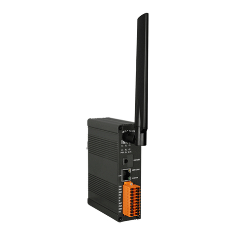
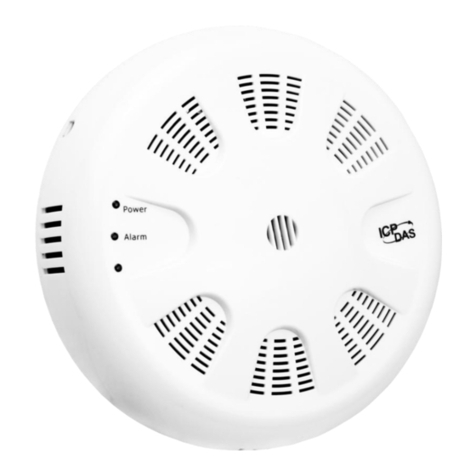
ICP DAS USA DL-1 S-WF Series User manual

DL-1xxS-WF Series User’s Manual
DL-1xxS-WF Series User’s Manual (Rev1.0,May/2022) ------------- 1
www.icpdas.com
Warranty
All products manufactured by ICP DAS are under warranty regarding
defective materials for a period of one year from the date of delivery to the
original purchaser.
Warning
ICP DAS assumes no liability for damages resulting from the use of this
product. ICP DAS reserves the right to change this manual at any time without
notice. The information furnished by ICP DAS is believed to be accurate and
reliable. However, no responsibility is assumed by ICP DAS for its use, or for any
infringements of patents or other rights of third parties resulting from its use.
Copyright
Copyright 2022 by ICP DAS. All rights are reserved.
Trademark
The names used for identification only may be registered trademarks of their
respective companies.

DL-1xxS-WF Series User’s Manual
DL-1xxS-WF Series User’s Manual (Rev1.0,May/2022) ------------- 2
Document Revision
Version Date Description of chan
g
es
Rev1.0 2021-03-08 First
r
elease for DL-1xxS-WF Series

DL-1xxS-WF Series User’s Manual
DL-1xxS-WF Series User’s Manual (Rev1.0,May/2022) ------------- 3
Table of Contents
1.Introduction ...................................................................................................... 4
1.1Features .............................................................................................. 5
1.1.1Features Description ........................................................................... 5
1.1.2Application ........................................................................................ 6
1.2Specifications ...................................................................................... 7
2.Hardware .......................................................................................................... 9
2.1Outward Appearance .......................................................................... 9
2.2Reset to Default .................................................................................. 9
2.3Connector & Pin Define .................................................................... 10
2.4Dimensions ....................................................................................... 12
2.5Wire Connection ............................................................................... 13
2.5.2Digital Output (DO) wiring ................................................................ 13
2.5.2Power Input ..................................................................................... 13
3.Software .......................................................................................................... 14
3.1DL-WF PC Utility & DL Series Android APP .................................... 14
3.1.1Main Screen ................................................................................... 14
3.1.2Device Status ................................................................................... 15
3.1.3Sensor & DO Output status ................................................................ 15
3.1.4Icon Button ...................................................................................... 16
3.1.5Configuration/Setup ....................................................................... 17
3.1.6IP Scanner ..................................................................................... 19
3.2Function page ................................................................................... 19
3.3Log & Chart page ............................................................................. 21
4.Modbus Protocol ............................................................................................ 22
4.1.2Function Code .................................................................................. 22
4.1.3Error Response ................................................................................. 22
4.2Data Encoding .................................................................................. 23
4.2.1Binary ............................................................................................. 23
4.2.216-bits Word .................................................................................... 23
4.3Modbus TCP Protocol Description .................................................... 24
4.3.1MBAP ............................................................................................. 24
4.4DL-1xx-WF Address Mapping (PLC Address Base = 1) ..................... 25
DL-1xxS-WF Series User’s Manual
DL-1xxS-WF Series User’s Manual (Rev1.0,May/2022) ------------- 4
1. Introduction
The DL-1xxS-WF Series Data Logger devices can be used to record temperature,
humidity and dew point information, including the date and time stamps for each record,
with up to 650,000 downloadable records(CSV) able to be stored. Real-time data can be
accessed from anywhere and at any time using the PC Utility, Android APP & Web. It
includes 2-channel Photo MOS Relay Output using trigger source and range for Alarm
Devices. DL-101S-WF include an LCD display, DL-111S-WF include an Illuminance
sensor.
DL-1xx-WF Series have WLAN connection complies with the IEEE802.11b/g/n
standards, support Modbus TCP protocol, TCP & HTML, Which makes perfect
integration for monitoring or control in SCADA software, HMI Modbus & Utility.
Figure 1-1: Application architecture for the DL-1xxS-WF

DL-1xxS-WF Series User’s Manual
DL-1xxS-WF Series User’s Manual (Rev1.0,May/2022) ------------- 5
1.1 Features
Wi-Fi communication monitoring and configuration
Compatible with IEEE 802.11b/g/n standards
Support Access Point(AP, 1 Client) & Station(STA) modes for wireless networks
Support WEP, WPA and WPA2 wireless encryption
Support Modbus TCP
Support DHCP Server(AP), DHCP Client or Static IP(STA) network configuration
Wide power supply range
Photo MOS Relay output
LCD Display Shows Temperature, Relative Humidity,
Dew Point, Date and Time (DL-101S-WF Only)
Illuminance measure (DL-111S-WF Only)
Up to 650,000 data logger records
IP66 Protection Approval
DIN-Rail or Wall Mounted
1.1.1 Features Description
Compatible with IEEE 802.11b/g/n standards
DL-1xxS-WF complied with IEEE 802.11b/g/n standard from 2.4~2.5 GHz, and it
can be used to connect your wireless LAN.
Support Access Point(AP) & Station(STA) modes for wireless networks
AP mode lets you create a Limited AP(1 Client access allow) network with the
specified SSID to communicate directly with each other without the need for a wireless
access point.
STA mode is the more common network configuration where all wireless clients
connect to the wireless network via a WAP (Wireless Access Point).
Support WEP, WPA and WPA2 wireless encryption
WEP and WPA are common types of security that are used to protect wireless
networks. When WEP or WPA is turned on, DL-1xxS-WF uses a special security key
combination to allow only devices that know this key to connect to its wireless network.
This applies to laptops, smart device, or any other wireless device.

DL-1xxS-WF Series User’s Manual
DL-1xxS-WF Series User’s Manual (Rev1.0,May/2022) ------------- 6
Support Modbus TCP protocols
The Modbus TCP server function on the DL-1xx-WF can be used to provide data
monitoring from HMI/SCADA software built with Modbus TCP driver.
Also, there is some other HMI Modbus App in Android Google Play you can use.
Data Logger up to 650,000 records
Including the date and time stamps for each record, with up to 650,000 downloadable
records CSV able to be stored. Each segment file size is 64Kbyte for 5376 record.
Chart View for PC Utility & Android APP
The DL-WF Series PC Utility & DL Series Android APP, can be used to configure
the module and monitor real-time data, as well as display the chart, setting alarm events,
setting the schedule or free run. The utility also allows the log data to be downloaded and
exported to a .CSV file analysis from any other software.
1.1.2 Application
Transportation of food or pharmaceuticals
Food and beverage industry
Blood stations, pharmacies
Building and energy management
Museums, archives, galleries
Warehouses

DL-1xxS-WF Series User’s Manual
DL-1xxS-WF Series User’s Manual (Rev1.0,May/2022) ------------- 7
1.2 Specifications
Table 1-1: System Specifications
Device DL-101S-WF DL-111S-WF
Illumination Measurement
Ran
g
e - 0 to 100,000 Lux
Resolution - 1 Lux
Accurac
y
-±5%
Response Time - 1 secon
d
Tem
p
erature Measurement
Ran
g
e -20 to +60°C (-31 to +176˚F)
Resolution 0.1°C
Accurac
y
T
y
pical: ± 0.4°C; refer to fi
g
ure 2
Relative Humidit
y
Measurement
Ran
g
e 0 to 100% RH
Resolution 0.1% RH
Accurac
y
T
y
pical: ±3% RH
@
20 ~ 80% RH; refer to fi
g
ure 1
LCD Dis
p
la
y
Display Information Date, Time, Temperature (°C and °F), Relative
Humidit
y
(RH), Dew Poin
t
-
Di
g
ital Out
p
ut
Channels 2
Output T
y
pe PhotoMOS, Form A, SPST
Max Load Curren
t
1000 mA
Load Volta
g
e 100VDC
Data Lo
gg
er
Records 650,000
Wi-Fi Interface
Interface Wi-Fi 2.4G
Standard Supporte
d
IEEE 802.11b/
g
/n
Wireless Mode Station & AP (1 Client)
Encr
y
p
t
ion WEP, WPA and WPA2
Service TCP, Modbus TCP, HTML

DL-1xxS-WF Series User’s Manual
DL-1xxS-WF Series User’s Manual (Rev1.0,May/2022) ------------- 8
Device DL-101S-WF DL-111S-WF
LED Indicators
Power/Status 2 colors LED, Blue for S
y
ste
m
status, Red for Wi-Fi connec
t
status.
Protection
Waterproof Level IP66
ESD (IEC 61000-4-2) ±8 kV Air for Random Point
EFT (IEC 61000-4-4) ±4 kV for Power
Environment
Operatin
g
Temperature -20 ~ +60°C
Stora
g
e Temperature -30 ~ +80°C
Humidit
y
5 to 95% RH, Non-condensing
Mechanism
Dimensions(WxLxH) 103mm x 135mm x 55m
m
103mm x 135mm x 67m
m
Ins
t
allation DIN-Rail/Wall Moun
t
Power Re
q
uirements
Input Volta
g
e Ran
g
e +9 ~ 48 VDC with Reverse Protection (+Vs to GND)
Consumption 0.28W(WiFi Connec
t
e
d
Standb
y
) 0.3W(WiFi Connec
t
ed Standb
y
)

DL-1xxS-WF Series User’s Manual
DL-1xxS-WF Series User’s Manual (Rev1.0,May/2022) ------------- 9
2. Hardware
2.1 Outward Appearance
Figure 2-1: DL-101S-WF/DL-111S-WF
2.2 Reset to Default
Figure 2-3: Switches inside the cover
Reset to default

DL-1xxS-WF Series User’s Manual
DL-1xxS-WF Series User’s Manual (Rev1.0,May/2022) ------------- 10
Remove the cover on the left side(Big cover), Press & hold the Reset
button on the bottom side over 6 Sec until the Red LED(Status/Alarm) quick
flash then release to restore device default setting. Default is set in AP mode.
2.3 Connector & Pin Define
Figure 2-4: Connector for Power / Alarm Relay Output

DL-1xxS-WF Series User’s Manual
DL-1xxS-WF Series User’s Manual (Rev1.0,May/2022) ------------- 11
2.4 LCD Display(Only for DL-101S-WF)
There are 6 items, Date, Time, Temperature (°C and °F), Relative Humidity (RH),
Dew Point for LCD display, it can select On or Off to show on each item using utility,
APP, or Web.
Time Date Temp °C Temp °F
Relative Humidity Dew Point

DL-1xxS-WF Series User’s Manual
DL-1xxS-WF Series User’s Manual (Rev1.0,May/2022) ------------- 12
2.5 Dimensions
The diagrams below provide the dimensions of the DL-1xxS-WF series to use in
defining your enclosure specifications. All dimensions are in millimeters.
Figure 2-4: Dimension of the DL-101S-WF
Figure 2-5: Dimension of the DL-111S-WF

DL-1xxS-WF Series User’s Manual
DL-1xxS-WF Series User’s Manual (Rev1.0,May/2022) ------------- 13
2.6 Wire Connection
2.6.2 Digital Output (DO) wiring
Figure 2-6: Photo MOS Output wiring
2.6.2 Power Input
Figure 2-7: Power Input

DL-1xxS-WF Series User’s Manual
DL-1xxS-WF Series User’s Manual (Rev1.0,May/2022) ------------- 14
3. Software
3.1 DL-WF PC Utility & DL Series Android APP
The Utility provides the simple way to operating and acquire status. It can use the
wireless network interface to configuration. Provide AP(Access Point) & STA(Station)
mode to connect the DL-1xxS-WF series. It is available on both Windows & Android
application to operating and configure the DL-1xxS-WF device.
PC Utility Support Windows 7 (or later versions) and Android 5.0 (or later versions).
The following is the main screens provided by Utility, these utility tools can be
thought as a useful tool for configuration and monitoring on the DL-1xxS-WF. It supplies
several functions, such as Monitoring, Control, Connection, Wi-Fi setting and F/W
upgrade, etc…
3.1.1 Main Screen
Figure 3-1: Utility main screen
(Windows Utility , Android App, WEB)

DL-1xxS-WF Series User’s Manual
DL-1xxS-WF Series User’s Manual (Rev1.0,May/2022) ------------- 15
3.1.2 Device Status
Show the connected controller information, user define Locate string, RSSI strength,
Device IP & Static IP button for changing device IP in STA mode.
3.1.3 Sensor & DO Output status
Show the Sensor value & DO Photo MOS output status.

DL-1xxS-WF Series User’s Manual
DL-1xxS-WF Series User’s Manual (Rev1.0,May/2022) ------------- 16
3.1.4 Icon Button
ICON function
Setup Open the Setup Screen (Android versions Setup
function under the icon)
Find Controller Red Led blinking, use to find the connected
Controlle
r
Refresh Refresh status
Function
1. PC Utility & HTML Function button use to
setup Schedule/Free run, Alarm item & range,
LCD display item(Only DL-101S-WF).
2. For Android APP, Function button is including
inside Menu
b
ar.
Offset Offset adjustment only for Android APP, PC
Utilit
y
& HTML is show as numbe
r
b
ox.
Data Log &
Chart
1. PC Utility Data Log manage & Chart view
button use to download data log from device
for chart view, save chart view buffer to CSV
& .dlb(Data Log Binary File), load binary file
to chart view.
2. For Android APP, Data Log & Chart button is
including inside Menu bar.
3. HTML do not include this function.
Menu
Menu list box include Setup, Function, Data Log
& Chart, FW Version & About, only for Android
APP.
Table 3-1: Icon Indicator

DL-1xxS-WF Series User’s Manual
DL-1xxS-WF Series User’s Manual (Rev1.0,May/2022) ------------- 17
3.1.5 Configuration/Setup
Figure 3-2: DL-WF Utility setup page
Click apply icon to save each subject’s setting, after finishing all setting click
to make device take effect on new setting
AP:
SSID Name
1. Default Controller’s SSID in Wi-Fi AP mode, will be DL-1xxS-WF-xxxxxx.
Note: xxxxxx is the last 6 characters MAC address of your device.
Key Type
AP mode SSID Key type (default is Open)
SSID Key
AP mode SSID Key, (default is None)
STA:
SSID Name
Wi-Fi AP’s SSID intent to connect (default is tWFHUB)
Key Type
Wi-Fi AP’s SSID Key Type (default is WPA/WPA2)
SSID Key
Wi-Fi AP’s SSID Key (default is 00000000)

DL-1xxS-WF Series User’s Manual
DL-1xxS-WF Series User’s Manual (Rev1.0,May/2022) ------------- 18
Static IP:
IP: Specific an IP that is not been used.
Mask: Default will be 255.255.255.0.
Gateway: Basically, define in the AP you are going to connect.
SSID Service Set Identifier: Connected devices must be the same SSID, SSID
len
g
th must not exceed 31 characters.
Key Type
Key of Encryption connected devices must with the same Key.
Open :No Key request.
WEP(Shared) :Key length must be 15 characters.
WPA/WPA2-PSK :Key length must between 8~15 characters.
Table 3-2: Station SSID & Key type configure
Wi-Fi Mode:
DL-1xxS-WF Device working mode (default is in AP)
AP (Access Point):
PC or Android Device connect to DL Device directly through
AP(Fixed IP:192.168.77.1), AP mode support only one connection, If Multiple
devices connect at a same time, only first connected devices can access.
STA(Station):
DL Device will auto connect to specific Wi-Fi AP, PC or Android Device
also need to connect to the same AP, then they can use those DL Device in same
domain.
*. Please check specific Wi-Fi AP is active and SSID/key is same as the setting
before use.
Location information:
Set the information for you to identify & locate those Controller easily, length
must under 31 characters.
Modbus Port:
Modify Modbus TCP Port (default is 502)
Modbus Idle Timeout:
Set Idle Timeout for Modbus TCP connection (default is 120 Sec) in
STA(Station) mode, recommend 30 Sec. when device in STA mode connect to an
AP, when device break connect with AP and lost connection, the device will hang in
a dead connection. To prevent this happen, set a timeout, the device will close the
connection and wait for next connect.

DL-1xxS-WF Series User’s Manual
DL-1xxS-WF Series User’s Manual (Rev1.0,May/2022) ------------- 19
3.1.6 IP Scanner
There are lots of free IP scanner tools in both Windows & Android OS, for
example “Advanced IP Scanner” for Windows, “Network Analyzer” for Android,
those are high performance scanner tools on each OS.
3.2 Function page

DL-1xxS-WF Series User’s Manual
DL-1xxS-WF Series User’s Manual (Rev1.0,May/2022) ------------- 20
Function page include Data Logger Config, Digital Output Control & LCD Display
Control.
Data Logger Config:
Enable Data Log
Start/Stop the Data Logger & save all capture date in memory. It will start from the first
record every time when enable start the Data Logger.
Record Mode
Select Data Logger running in Schedule or Free Run mode.
Record full action
Select the action roll over Overwrite record or Stop the record when Data Logger record full.
Schedule Start/Stop Date Time
To set the Start/Stop Date/Time when select Data Logger running in Schedule mode.
Sampling Interval
Select the interval time for sampling.(5,10,15,30Sec,1,5,10,15,30Min,1,12,24Hr)
Digital Output Control (DO0/DO1):
Trigger Source
Select which item for trigger the DO Photo MOS active,
0: Disable
1: Temperature ℃
2: Temperature ℉
3: Humidity %RH
4: Dew Point ℃
5: Luminance lux. (Only for DL-111S-WF)
Output Mode
Select DO output mode 0: Latch or 1: Momentary(1sec).
Active Range
Lower Limit/Upper Limit
Set the value active between Lower & Upper limit.
LCD Display Controller (Only for DL-101S-WF):
There are 6 items, Date, Time, Temperature (°C and °F), Relative Humidity (RH),
Dew Point for LCD display, it can select On or Off to show on each item using utility,
APP, or Web.
Slide Interval
Select a value of second for LCD switch between each item.
This manual suits for next models
2
Table of contents
Other ICP DAS USA Data Logger manuals

ICP DAS USA
ICP DAS USA DL-300-WF Series User manual

ICP DAS USA
ICP DAS USA ET-7044 User manual

ICP DAS USA
ICP DAS USA MDC-211-WF User manual

ICP DAS USA
ICP DAS USA ET-7053 User manual

ICP DAS USA
ICP DAS USA CAN-Logger Series User manual

ICP DAS USA
ICP DAS USA DL-110S-E User manual

ICP DAS USA
ICP DAS USA I-7067 User manual

ICP DAS USA
ICP DAS USA M-7026 User manual

ICP DAS USA
ICP DAS USA PIR-23-WF Series User manual

ICP DAS USA
ICP DAS USA DL-100S-E User manual