Metal Samples Company MS3500E User manual

MS3500E/3510E
Remote ER Data Logger
MetalSamplesCompany
A Division of Alabama Specialty Products, Inc.
152 Metal Samples Rd., Munford, AL 36268 Phone: (256) 358-4202 Fax: (256) 358-4515
E-mail: [email protected] Internet: www.metalsamples.com

.

Table of Contents
I. Introduction ......................................................................................................................1
A. InstrumentFunctionOverview .................................................................................1
B. InstrumentPartsList................................................................................................ 2
II. Installation ........................................................................................................................3
A. EnclosureandMountingDetails...............................................................................3
B. BatteryInstallation................................................................................................... 4
C.4-20mALoopInstallation ........................................................................................5
D. Probe-InstrumentConnection.................................................................................. 6
E. DataDownloadConnection(s)................................................................................. 7
III. SetupandOperation .........................................................................................................8
A. Main Menu Overview ............................................................................................. 8
B. Program Setup ...................................................................................................... 10
1. Set Time and Date ..................................................................................... 10
2. Enter Probe ID .......................................................................................... 11
3. StartDataLogging..................................................................................... 12
C. Measure ProbeFunction ....................................................................................... 13
D. ViewStored DataFunctions.................................................................................. 14
E. SetReadingIntervalFunction ................................................................................ 15
F. DownloadingData ................................................................................................. 16
1. Upload to PC ............................................................................................ 16
2. Upload to MS1500E ................................................................................. 25
G. SystemShutdownFunction.................................................................................... 26
H. TestMode Function .............................................................................................. 26
I. DataInterpretation ................................................................................................. 27
1. ProbeReading........................................................................................... 27
2. Metal Loss ................................................................................................ 28
3. Corrosion Rate .......................................................................................... 28
4. 4-20mA Output ......................................................................................... 29

IV. ERTechnique-General .................................................................................................. 30
A. Measurement Theory ............................................................................................ 30
B. ERSensingElements ............................................................................................. 32
C. ERElementPerformance ...................................................................................... 34
D. ERProbe Body Design ......................................................................................... 38
AppendixA-MS3500ESpecifications ................................................................................... 41
AppendixB-Testingthe MS3500E/MS3510E with theERMeterProver .............................. 42
Appendix C - MS1500E Select Probe ID............................................................................... 44
AppendixD-ReturninganInstrument for Repair .................................................................... 47
AppendixE-Warranty .......................................................................................................... 49
AppendixF-InstallationDrawingofMS3500EinHazardousLocation ................................... 50

1
I. Introduction
A. InstrumentFunctionOverview
TheMS3500E/3510EDataLoggerisdesignedto provide a continuous record ofcorrosiveactivityin
remotelocationsthatareinfrequentlyvisited, such ascross-countrypipelines,andunmannedproduction
platforms.However,thisunitfindsequalapplicationinlocationsthatareinconvenientordifficultto
accessona regular basis, suchasrefineryoverheads,andflue-gasstacks.
TheMS3500E/3510Eiscompletelyself-containedwiththeonboardbatterysystemsupplyingthetotal
powerrequirementfor operation. It canbeusedwithanyof Metal Samples’ ERprobes,orthoseofall
othermajormanufacturers.Onceinplace,itwillautomaticallyreadtheprobeatcustomer-selected
intervalsandstoretheresultingdataintheunit’sonboardmemory.Theonboardmemorywillcollectup
to3,100datapointsbeforedata download is required. The datacollectionintervalisprogrammablein
hourlyincrements.Evenattheminimumdatacollectioninterval(1hour),datadownloadingneedonlybe
performedeveryninetydays.Withmore practical data collection intervals (8 - 12 hours), the unit may
beunattendedfor as longas6-8months between downloading operations.
Anoptical,infrared,RS232communicationlink is provided for datadownloadtoeitheraPCorMetal
Samples'MS1500E portable ERdatalogger.Downloadeddata may beanalyzed,reviewed,or re-
portedbyconventionalspreadsheet,database, or mathematical software packages.
Theinfraredcommunicationlink isanintegralpartoftheintrinsicallysafedesignoftheMS3500E/
3510E.Opticalinsteadofelectrical,thisuniquefeaturepermitsdatadownloadingwithoutremovingthe
instrumentor“memorymodule” fromthehazardousarea.
AnotheruniquefeatureoftheMS3500E/3510Eis the highlevelofonboardintelligence.Thetwo-line,
20-characterLCDallowsvisualreviewofallhistoricaldatainmemoryandreads directly as “total metal
loss”and/or“averagecorrosionrate”. Thisisincontrasttoothercommerciallyavailableunits that store
anddisplayonlytheraw “resistanceratio”thatrequiresadditionalmanipulationtoprovideusefuland
intelligibledata.
TheLCDscreen,togetherwiththe2-keymembranekeypad,provides a user-friendly,interactive,
promptingsystemthatis used for bothsystemsetupanddatareview.ThismakestheMS3500Ethe
mostadvancedunitofits type on the market.
Byaddinga4-20mAcommunication facility, the MS3500E becomes an MS3510E.Thisallows
continuoustransmissionofdata, via a 4-20mAloop,to a plant computer orcentraldatalogger, for
integrationwithotherreal-timeprocessparameters.This data transmissioncanbeaccomplishedwithout
disruptionoftheunit’s basic logginganddatastorageoperations.The 4-20mAloopextends the capa-
bilitiesoftheunittoincludeconventional,in-plant,real-timedatacommunication.
TheMS3500E/3510Eunitusesastainlesssteel NEMA 4X (IP 66) enclosure, makingitsuitableforuse
inthemostextremeofoutdoorconditions.

2
B.InstrumentPartsList
TheMS3500E/MS3510Eissuppliedwiththefollowingaccessories.
Partno. Qty. Description
ET0133 6 1.5V,AADryCells(Installed)
ET0612 1 4-20maLoop Connector (MS3510EOnly)
IN3500-2 1 OptilinkCable
IN3500-4 1 10 Ft. Probe Cable
IN3500-5 1 MeterProver
IN3500-6 1 SerialPortAdapter
IN3500-7 1 OperationsManual
Uponreceiptoftheinstrument,theusershouldverifythattheabovelistedaccessoriesareincluded.
Anyshortageshouldbereportedimmediately to:
Metal Samples
Phone:(256) 358-4202
Fax:(256) 358-4515
E-mail:[email protected]

3
II. Installation
A.Enclosure&MountingDetails
TheMS3500E/3510Eenclosureisfabricatedin carbon steel with a baked-on,high-buildepoxy
coating.Theunithasahinged door that is secured,whenshut,byscrew-downclampsthatdiscourage
unauthorizedtampering.TheenclosureisconstructedtoNEMA4X(IP66)weatherproofstandards,
makingitsuitableforthe mostrigorousofoutdoorenvironments.
Theoveralldimensionsoftheunitare12-1/4"(height),9"(width),4-3/8"(depth),makingitaconve-
nientsizetomounteveninthemostconfinedoflocations.Forthebestresults, the instrument should be
mountedwithintenfeetoftheprobelocation.Tofacilitatethis,theunit hasaversatilemountingflange
withfour.31"diameter,mountingholes.Overalldimensionsandmountingholecentersareshownin
Figure1.
Figure 1. MS3500E Dimensions

4
B.BatteryInstallation
TheMS3500E/3510Einstrument uses six 1.5V,AAsize batteries,connectedinseries,asaprimary
powersource. While anyAAsize battery canbeused,Duracell or ProcellTypeMN1500 or PC1500
batteriesarerequiredtomeettheintrinsicsafetycertificationrequirements.SincetheMS3500E/3510E
operatesinalowpowerconsumptionmodebetweenreadings,batterylifewillbeafunctionofthe
readingintervalandmeasurementtimecyclesetbytheuser.Atthemostfrequentreadinginterval(1per
hour),aminimumbatterylifeoffourmonthsistobeexpected.Morepracticalintervals,suchasevery
12or24hours,willyieldabatterylifeinexcessoftwelvemonths.Generally, to avoid unexpected
powerdrains,batteriesshouldbe replaced once everysixmonths.Intheinstanceofalowreading
interval(1per4hoursorless),threemonthlybatteryreplacementsisadvisable.
Batteriesaremountedin the back of theMS3500E/MS3510E,behindtheinstrumentscreenand
keyboardpanel. Thebatteries are accessed bylooseningthetwothumbscrewsonthe right sideofthe
panel,thenswingingthehingedpanelopentotheleft. Careshouldbeusedwhenopeningandclosing
thepaneltoensure that the internal wiringisnotpinchedordamaged. Oncethepanelisopened,
batteriescanbeinserted or removed fromthespring-loadedretainerasshownbelow.
Figure2. MS3500E BatteryInstallation
+
-
+
-
+
-
+
-
+
-
+
-

5
C.4-20mALoopInstallation
TheMS3510Eisprovidedwitha4-20mAcommunication outletthatallowscontinuous,real-time
integrationofERcorrosiondatawithotherprocessparametersinthemainplantcomputer.The
4-20mAoutlet port isa2-pinmilitaryconnector (MIL 14S-9SF)onthe base of theunit,marked
4-20mA.Thematingconnector for this outlet (ET0612)issuppliedaspartoftheaccessoriesfor the
MS3510Eunit.Thepositiveleadofthecommunicationloopshouldbeconnectedtothe“A” terminal of
theET0612mating connector,and the negative leadtothe“B”.Theloopcanthen be connected tothe
4-20mAinstrumentoutlet:
Figure 3. MS3510ECurrentLoopTermination
Theloop should bepoweredby 10-24 VDC. Forhazardousapplications,an appropriate Zener
barriershouldbeinstalledintheloop,orpowershouldbesuppliedfromanintrinsicallysaferepeater
powersupply. Typicalhazardousinstallationisshownonpage49.
Corrosion Monitoring Systems
Metal Samples
PIN 'A' (+ CURRENT LOOP)
PIN 'B' (- CURRENT LOOP)
VIEW A-A
2-PIN MALE CONNECTOR
(VIEWED FROM SOLDER-SIDE)
AB
AA
MS3510E Connections
PROBE 4-20
mA
OPTI-LINK
DATA PORT

6
D.Probe-InstrumentConnection
TheMS3500E/3510E canbemounted directly ontoanER probe, oronto an HA700110-5 probe
adaptorinthecase of a retrievable probeusedinatwo-inch,high-pressure,accessfitting(see Figure
12,p.41).However,inmanyinstancesitiseitherinconvenientorundesirable to mount theinstrument
directlyontothe probe. Forthesecircumstancesa546810,ten-foot, extension cable isprovided.The
extensioncablehasintegralconnectors withaguidingkeywaytoensurecorrectpinalignment when
attached.Thefemaleconnector (MS3106E145-6S) mateswiththe probe, orHA700110-5probe
adaptor,andthe male connector mateswiththecentralterminalonthebase of the MS3500E/3510E
unit.
The length of the extension cable has been carefully determined so as to avoid excessive
signalnoise. Longerextension cablesshouldonly beemployed afterconsultationwith Metal
Samples.
TheextensioncableprovidedwillmatedirectlywithanyMetalSamples’ERprobeorthoseofany
othermajor manufacturer,orwithanHA700110-5 probe adaptor inthecaseofretrievable probes.

7
E.DataDownloadConnection
To downloaddatafrom the MS3500Etoa PC usetheOptilink Cable andSerialPortAdaptor.
Note:Do NOTplugthephonejack ontheend ofthe OptilinkCabledirectly intoyour PC's
modem.
Ifa serial portisunavailableonyour PC andyouwishto connect theMS3500Etoyour PC via aUSB
port,you may useaserial to USBconverter.Thisconverter is notincludedwith the instrument,butmay
bepurchasedseparatelyatmajorelectronicsretailers.
To downloaddatafromthe MS3500E to aMS1500Econnectthe Optilink Cabledirectlytothe
MS1500E.
Detailedinstructionsofdatadownloadingaregivenonp.16.
UPLOAD TO PC
(SAFE AREA ONLY)
UPLOAD
TO MS1500
MS1500 HANDHELD
DATA-LOGGER
OPTI-LINK CABLE
MS3500/MS3510
DATA-LOGGER
Ò
US
S
I
L
E
T
D
REMOTE ER DATA LOGGER/TRANSMITTER
MS3510E
MS3500 SERIAL
PORT ADAPTER
SERIAL TO USB
ADAPTER (OPTIONAL)
TO
COMPUTER
SERIAL
PORT
TO
COMPUTER
USB
PORT
Corrosion Monitoring Systems
Metal Samples
Corrosion Monitoring Systems
Metal Samples
ER Data Logger
MS1500E
123
456
789
0
Exit Enter
Figure4. Data DownloadConnections
8
III. Setup and Operation
A.MainMenuOverview
Oncethebatteriesareinstalled in the MS3500E/3510E, the instrumentscreenmaybeactivatedby
pressingeitherofthekeysonthefrontpanel.Thecompanyname“METALSAMPLES”andsoftware
versionwillappear, thenafterafewsecondswillautomaticallychangetothe first ofthefunctionscreens
thatconstitutesthemainmenu.
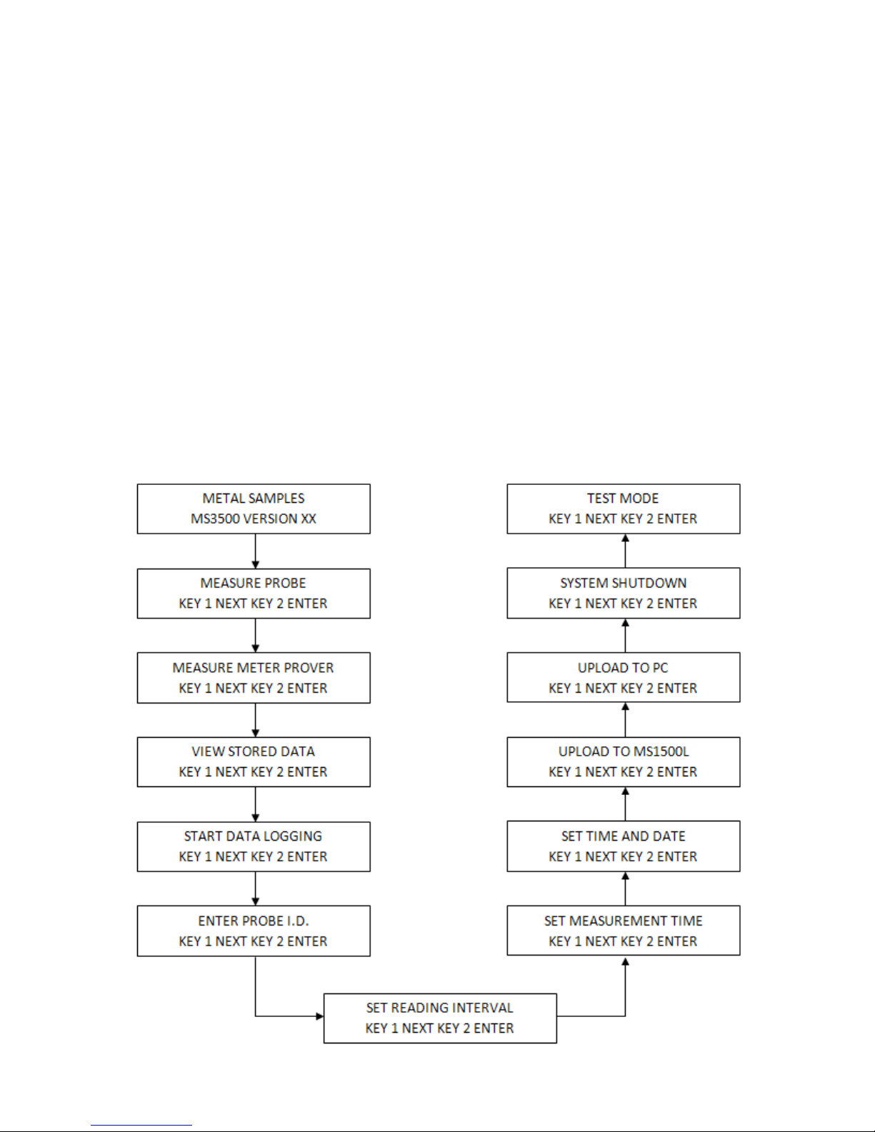
Aseriesofninefunctionscreenscanbeaccessedsimplyby scrolling using KEY1ontheinstrument
keypad.Eachoftheninefunctionscreensallowsentryintoasubmenutoinitiateanactionsuchas
MEASUREPROBEorSTARTDATALOGGING;alternativelyitallowsinputofdatasuch as probe
identificationorreadinginterval.
Eachofthefunctionscreensandtheirsubmenusare fullyexplainedlaterinthemanual.Thefollowing
diagramshowsthesequenceofaccesstothe ten function screens:

9
Asexplained,eachfunctionscreengivesaccesstoasubmenu,thepurposeofwhichisbrieflydescribed
below:
MEASUREPROBE. Thiswilloverridethenormal intervalofloggingreadingstoallow
aspot checkreadingto be obtainedonscreen.
MEASUREMETERPROVER. Used totesttheinstrument with theMeterProver.
VIEWSTOREDDATA. Allowsvisualreviewofallreadingslogged.
STARTDATALOGGING. Initiatesthedataloggingprocessafterinputofappropriate
start-updata.
ENTERPROBEID Allowsinputof probe type and readinginterval. Togetherwith"SET
TIMEANDDATE". Thisconstitutesinitialstart-updata.
SETREADINGINTERVAL. Thisallows the initialreadingintervalthatisinputunder
"PROBEID"tobechangedwithoutdeletingstoreddata.
SETMEASUREMENTTIME. Thisallowstheinitialmeasurement (polarization) timethatis
inputunder"PROBEID"tobechangedwithoutdeletingstoreddata.
SETTIMEANDDATE. This constitutes the initialstepofstart-updata,allowingcorrect
settingofthe“realtime”clock.
UPLOADTO MS1500L. This activatesthedownload ofstoreddata to theMS1500Lor to
apersonalcomputer.
UPLOADTOPC. This activates the downloadofstoreddata to apersonalcomputer.
SYSTEMSHUTDOWN. Thiswillstoptheloggingprocess,andminimize power
consumptionwithoutdeletingstoreddata.
TESTMODE. Thisallowsacalibrationcheck of the 4-20mA loop, and supplies instrument
troubleshootingdata.

10
Thescreenoftheinstrumentisinitially activated bypressingeitherkey. The “SETTIME &DATE”
functionscreenisthenaccessedbyscrollingthroughthemainmenuusingKEY 1. KEY 2 allows entry
intothesubmenu,andthetimeanddate setup screen will be shown. Each digitofthetime,day,month,
andyearissequentially set using KEY1toselecttheappropriatedigit,and KEY 2 toenterthedigit
andmovethenextdigitof the time and date sequence.
Oncethefinaldigitoftheyearisentered,usingKEY2,thescreenwillautomaticallychangetothetime/
datedisplayscreen.Thisscreen shows the time anddateassetup.KEY2willacceptand store this time
anddate.KEY1 will reject this information.Eitherkeywillautomaticallyreturntheuserto the “MEA-
SUREPROBE”screenofthemain menu.Ifthetimeanddatehasbeenrejected, scrolltothe“SETTIME
&DATE”functionscreen,reenter the submenu and make the necessary corrections. If the time and date
arecorrect, and theuserhas used KEY2toaccept the information,scrollto the “ENTERPROBEID”
functionscreentocontinuewithprogram setup.
Pleasenote thatthetime anddate, onceset, shouldnot requirealteration exceptafter battery
replacement.Should theuser decidetochange thetimeand datewhile probedatais storedin
memory,all datawillbedisplacedin timeandhighlyinconvenient tointerpret.
B.ProgramSetup
Havinginstalledthebatteries,theMS3500Eisreadyfor start-up programming whichcompromisesthe
followingsequence: • SETTIMEAND DATE
•ENTER PROBEID
•STARTLOGGING
1.Set Time and Date
Thisoperationisillustratedbelow:

11
2. Enter Probe ID
Thisfunctionwillallow theusertoidentifytheparticular probetypeorinstallationlocationwith aunique,
4-digittagnumber.Additionally,itallowstheselectionofcorrectprobe element geometry,whichis
necessaryfortheinstrument’s calculation of metallossandcorrosionrate.Finally,itallowstheuserto
selectthedatacollectionrate.Theoperationalsequenceisasfollows:
Oncethe“ENTERPROBEID”functionscreenislocated on the main menu, KEY 2 willgiveaccessto
thesubmenu.Theinitialscreenof thesubmenuallowsdeletionofanystoreddata.Normallythere will
benodatastored,since any useful data set willhavebeenpreviouslydownloaded.Ifnousefuldatais
storedintheunit, press KEY 1 whichwilldeleteallexistingdataandgiveaccess to the ProbeID
screen. Ifuseful dataisstored, useKEY2 toreturnto themainmenu anddownloadexisting
data(p.16) priortoproceeding.
TheProbeIDscreenallowsyoutoinserta4-digitidentificationnumberfortheprobeand/ormonitoring
location.EachdigitisselectedwithKEY1,andindividually entered with KEY2.
WhenthefourthdigitoftheID numberisentered,thescreenwillautomaticallychangetotheelement
identificationscreen.
TheelementidentificationscreenshowstheProbeIDnumberanda5-6digit/lettersequencethat
identifiestheprobeelementgeometryandthickness.KEY1allowstheusertoscrollthroughthe
elementidentifications,andKEY2willentertheappropriateelementIDonceitislocated.
It should be noted that the variety of element geometries and thicknesses that is offered by
thevarious probemanufacturerstends toincrease.Consequentlyitis possible,fromtime to
time,that theusermay encounteraprobe elementstylethat isnotincludedinthe instrument
look-up table. In such a case, the user may select any of the element geometries in the table,
except wire, that has the same thickness as the element under consideration.
UponentryoftheprobeelementID,thescreenwillautomaticallychangetothedatacollectionrate
screen.Thisallowsthe user to selectthefrequencywithwhichtheprobeshouldbe read. This canbe
setinhourly increments from ashighasonceperhourtoas low as onceevery2,475hours.Thereading
frequencyisseton the screen asdays(twodigits)andhours(twodigits).The default reading is 1per
hour.Each digit is selected byaKEY1 scroll, and individually enteredwithKEY2.Oncethelasthour
digitisentered,thenextscreenwillbedisplayedwhichshowsthereadingfrequencyasentered,which
canthen beaccepted(KEY 2) orrejected (KEY 1).Ifaccepted, the screenwill revert tothe“MEA-
SUREPROBE”function screen, and theusercanproceedtothe“STARTDATALOGGING” func-
tion. Ifrejected,thescreenwill also revert to the “MEASUREPROBE”functionscreen,buttheuseris

12
3. Start Data Logging
Thisisthesetofcommandsthatstartstheloggingprocess:
Thesubmenuisenteredfromthe “STARTDATALOGGING” mainmenufunctionscreen,usingKEY
2.Thefirstsubmenuscreenisthe“SYSTEMREADY” screen, fromwhichKEY2willstartthelogging
processand shut downthescreenfor power conservation. If,foranyreason, the userdoesnotwish to
commencelogging,KEY1willallowescapetothe“MEASUREPROBE” screen of themainmenu.
Onceloggingisactivated,it willcontinueuntiltheuseractivatesthesystemshutdownroutine,orthe
batteriesdischarge.Ineitherevent,alldatacollectedtothispointwillberetained,butnoadditionaldata
willbecollected.Enteringanew probeIDwillalsostoptheloggingprocessand eliminateallexisting
probedata fromthememory; prior toenteringnewprobeID,ensurethat allusefuldata is
downloaded.
Shouldloggingcontinueinanuninterruptedfashionuntilthememorycapacityoftheunitisfull,additional
datawillsequentiallyoverwritetheinitialdatapointsstoredinmemory.
Theuser shouldalwaysset adownload scheduleofsufficient frequencysothat nomore than
3,100readings aretakenbetween downloadoperations.
Note: Evenat thehighestfrequency(1perhour),downloading canbescheduled at
intervalsasgreat as129withoutdata corruptionbyoverwriting.
nowrequiredto access the“PROBEID”functionand reset/correct the probeID,theelementID, and
thereadingfrequencypriortocommencing with thedataloggingprocess.
UponentryoftheprobeelementID,thescreenwillautomaticallychangetothedatacollectionrate
screen.Thisallowsthe user to selectthefrequencywithwhichtheprobeshouldbe read. This canbe
setinhourly increments from ashighasonceperhourtoas low as onceevery2,475hours.Thereading
frequencyisseton the screen asdays(twodigits)andhours(twodigits).The default reading is 1per
hour.Each digit is selected byaKEY1 scroll, and individually enteredwithKEY2.Oncethelasthour
digitisentered,thenextscreenwillbedisplayedwhichshowsthereadingfrequencyasentered,which
canthen beaccepted(KEY 2) orrejected (KEY 1).Ifaccepted, the screenwill revert tothe“MEA-
SUREPROBE”function screen, and theusercanproceedtothe“STARTDATALOGGING” func-
tion. Ifrejected,thescreenwill also revert to the “MEASUREPROBE”functionscreen,buttheuseris
nowrequiredto access the“PROBEID”functionand reset/correct the probeID,theelementID, and
thereadingfrequencypriortocommencing with thedataloggingprocess.

13
C. MeasureProbeFunction
The“MEASUREPROBE”functionallows the user to makeaspot-checkprobereadingatanytime,
withoutconstraintofthenormallogginginterval. Thesubmenusequenceisillustratedbelow:
Thefirstscreenofthe“MEASUREPROBE”submenudisplaystheprobeIDnumber,elementgeom-
etryandthickness.KEY1exitstothe main menu “MEASURE PROBE” function screen andKEY2
willactivateameasurement.
IfKEY2isused to activate a measurement,thesecondsubmenuscreenwillbeshownthatdisplaysthe
probeID,elementgeometryandthickness,anda“PLEASEWAIT”notation.After approximately 30
seconds,thereadingwillbecomplete and thethirdsubmenuscreenwillbeautomaticallydisplayed.This
screenwillshow the current probereadingasanintegerbetween0-1000, and will giveaKEY1EXIT
option,anda KEY 2ENTER(save)option.KEY1 will returntheusertothe“MEASURE PROBE”
functionscreen,KEY2willsave the probereadingandautomaticallydisplaythefourthsubmenu
screen.
Thefourthsubmenuscreen displays metal lossinMILSandaveragecorrosionrateasMPY. After
approximately30seconds,thisscreen willautomaticallyreverttothe“MEASUREPROBE”mainmenu
screen. Thismainmenuscreenwillautomaticallyshutdowntothepowersaving modeafterfiveminutes.
Normaldataloggingcontinuesthroughout themeasureprobesequencewithoutinterruption.

14
D. View Stored Data Functions
Thisfacilityallowsall data stored intheMS3500E/3510Etobecalledupon the screen forreview. The
submenusequenceisshownbelow:
Afterpressing either keytoaccesstheMS3500E/3510E screen, KEYlisused to scrolltothe“VIEW
STOREDDATA”functionscreen. KEY2isthenusedtoenterthesubmenu.
Thefirstsubmenuscreendisplaysthelatestreadingnumber, thedateofthereading,andthereadingin
“probeunits”.Thereadingnumberismerelythetotalnumberof readings stored upto,andincluding,the
readingdisplayed.Theprobeunitreadingis an integer from 0 to1000thatindicatesthepercentageof
effectiveprobethicknessconsumed.Previousreadingsmaybeaccessedsequentially using KEY 2.
KEYlwillexitthereviewscreenand display metal loss (MILS) and averagecorrosionrate(MPY)for
thereadingnumberdisplayedwhentheexitkeyisused.Themetalloss/corrosionratescreen will
displayforapproximately30secondsbefore automaticallyreturningtothe“MEASUREPROBE”
functionscreen.
The“VIEWSTOREDDATA”functionmaybeusedatanytimewithoutdisruptingnormallogging.

15
E.SetReadingIntervalFunction
Thisfunctionpermitsthereadingintervaltobechangedatanytimeduringloggingwithout
disruptingtheloggingprocessordeletingthestoreddata.Theoperationsequenceisasfollows:
Afterany key isusedtoactivate the screen,KEY1is used toscrolltothe “SET READINGINTER-
VAL”mainfunctionscreen. KEY2thenallowsentryintothesubmenu.
Thecurrentreadingintervalisdisplayedasdays and hours.IndividualdigitsmaybealteredusingKEY
1,andenteredusingKEY2.Afterthefinalhourdigitisentered, the screen will automatically changeto
areadingintervalconfirmationscreen.Theintervalasenteredis displayed. KEY 1willexittothe
“MEASUREPROBE”mainfunctionscreenwithoutentering(saving)thenewinterval.KEY2willenter
(save)thenewreading interval,thenautomaticallyreturntothe“MEASUREPROBE”mainfunction
screen,furtherloggingtakingplaceatthenewreadinginterval.

16
F.DownloadingData
Datastored in theMS3500E/3510Eunitmaybe downloaded, viatheOpti-Linkport, directly to aPC.
Alternatively,datamaybedownloaded to Metal Samples’MS1500E Hand-Held Data Logger, and
subsequentlytransferredtoaPC.Directdownloadingisusuallypreferredinacontrolroomor
laboratoryenvironment.WhereseveralMS3500E/3510Eunitsare distributedinafieldenvironment,
thedatais most convenientlytransferredviatheMS1500E to a PC.TheMS1500Ewillaccept data
fromasmany as onehundredMS3500E/3510Eunitsforsubsequent transfer toaPC.
1.Upload toPC
To transferdatatoaPCit is necessary toinstalltheCorrosionDataManagement Software.
ToruntheCorrosionDataManagementSoftware, you need a PCthatmeetsthefollowing
requirements:
•Pentium®classprocessor
•Windows®95 orhigheroperatingsystem
•16 MB of RAM
•10MB of available hard-diskspace
•VGAmonitorwith800 600orgreaterresolution
•Mouseorpointingdevicerecommended
•Available 9-pin serial port orUSBport
•CD-ROMdriveforsoftwareinstallation
To installtheCorrosionDataManagementSoftware:
1. Insert the setupdiskprovidedinyouraccessorykit.
2. You will bepromptedtocloseany open programs. Afteryouhavedone so, clickOK to
continue.
This manual suits for next models
1
Table of contents
Other Metal Samples Company Data Logger manuals


