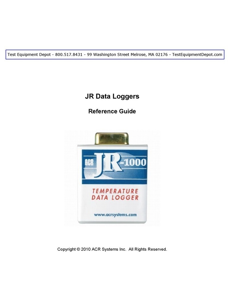
ACR Systems OWL 100 User manual

Table of Contents
Foreword 0
Part I Introduction to OWL Data Loggers 3
................................................................................................................................... 41 Features
................................................................................................................................... 42 Description
................................................................................................................................... 53 How OWL Data Loggers Take Readings
................................................................................................................................... 54 How to use OWL Data Loggers
................................................................................................................................... 75 Installation
................................................................................................................................... 86 General Specifications
................................................................................................................................... 97 Approvals
................................................................................................................................... 98 How to use this Guide
................................................................................................................................... 109 Comments and Suggestions
................................................................................................................................... 1010 Limited Warranty
Part II OWL Temperature Data Logger (Internal
Sensor) 11
................................................................................................................................... 111 Description
................................................................................................................................... 112 Setup and Use
................................................................................................................................... 123 Specifications
................................................................................................................................... 124 Applications
Part III OWL Temperature Data Logger (External
Sensor) 13
................................................................................................................................... 131 Description
................................................................................................................................... 132 Setup and Use
................................................................................................................................... 143 Specifications
................................................................................................................................... 164 Applications
Part IV OWL Electric Current Data Logger 17
................................................................................................................................... 171 Description
................................................................................................................................... 182 Setup and Use
................................................................................................................................... 193 Current Probesand Accessories
................................................................................................................................... 204 Specifications
................................................................................................................................... 205 Trouble-shooting
................................................................................................................................... 206 Applications
Part V OWL DC Voltage Data Logger 21
................................................................................................................................... 211 Description
IContents
I
© 2001 ... ACR Systems Inc.

................................................................................................................................... 212 Setup and Use
................................................................................................................................... 233 Choosing Transducers
................................................................................................................................... 254 Specifications
................................................................................................................................... 255 Applications
Part VI OWL 20 mA Data Logger 26
................................................................................................................................... 261 Description
................................................................................................................................... 262 Setup and Use
................................................................................................................................... 273 Choosing Transmitters
................................................................................................................................... 284 Specifications
................................................................................................................................... 295 Applications
Part VII OWL 200 and Custom Equations 30
................................................................................................................................... 301 Creating a ThermistorEquation
................................................................................................................................... 322 OWL Calibration
Part VIII APPENDIX A 34
................................................................................................................................... 341 Temperature Ranges
Index 0
OWL Data LoggersII
© 2001 ... ACR Systems Inc.

Introduction to OWL Data Loggers 3
© 2001 ... ACR Systems Inc.
1 Introduction to OWL Data Loggers
OWLs are easy-to-use battery-powereddata loggers. Pocket-sized and rugged,they can be used in a
wide range of environmental and industrial applications. Thereare a number of models available to
directly measure and record variables such as temperature, electric current,analog voltage, and
current loop. Each model canreliably record up to 10 years of time-based data for later analysis,by
TrendReader Software,on any IBM PC or100% compatible computer.

OWL Data Loggers4
© 2001 ... ACR Systems Inc.
1.1 Features
The OWL logger features:
·opticaldata transfer
·opticalflashing alarm
·selectivemeasurement ranges
·holds over 32,000 readings
·Polyurethane water-tight case
·Noryl Plastic water-tight snap case
·water-tight connector for external inputs
·typical 10year battery life
·on-board serialidentification
·mounting magnet and locking hole
Software for theOWL includes:
·easy modefor non-technical users
·advanced options such as:
1. stop when full or first-in first-out data storage
2. time delayedstartup
·highand lowtrigger points
·variablememory size
·programmable identification
·TrendReader™ interface
·opticalwand for logger setup and data retrieval
1.2 Description
OWL Data Loggers™ record readings continuouslyat a fixed sample interval.Using an optical data
link, ittransfers these readings to an IBM PC or 100% compatible computer for analysiswith ACR's
TrendReader™ software. Self-containedoperation and itssmall size permit easy installation. The
internal lithium battery lasts typically upto 10 years or at least 1,000 backups. Unique identification
names stored in each logger allow for convenient tracking.
A 32,768 byte unlimited-write-cyclememory is used to store themeasurements from an 8-bit
(equivalent to 10-bit resolution on narrow ranges) Analog to Digital Converter while a quartz crystal
oscillator keeps track of time.

Introduction to OWL Data Loggers 5
© 2001 ... ACR Systems Inc.
1.3 How OWL Data Loggers Take Readings
OWL Data Loggers canstore 32,767 readings.Once thememory is full, theOWL can be setup to
either bump the oldest reading to make roomfor the newest (sliding window of 32,767 readings) or
stop recording.
You can set the frequency at which your logger takes readings through the software. At a sample rate
of eight seconds, one reading is taken everyeight seconds and saved to memory. As you slowthe
sample rate the logger begins to average readings before savingthem to memory. To do this the
logger takes a reading every eight seconds, but insteadof transferring this directly to the logger's
memory, it stores the readings ina buffer (a temporary memory) where it is retained untilthe sampling
interval is over.
When you backup a logger's data onto yourcomputer, thecorrect timeand date are referenced to
each reading. All readings are then individually time and date stamped and processed by an equation
associated with the data logger channel. The result is a collection of accurate time-based data ready
for detailedgraphingand analysis.
1.4 How to use OWL Data Loggers
Using your OWL Data Logger for most applicationsis a simple process. With proper planning, setup,
installation and retrieval of your data logger, you can beassured that the information you collect will be
both correct and useful. This section providesgeneral procedures for using OWL Data Loggers. For
additional and specific information on these steps, refer to the chapter in this manual that deals with
the particularOWL model you have.
How to Communicate
In order to setup or get your logged data, youmust interface theOWL with thePC. The software
section of this reference guide explains in detail how to configureyour PC's communication port with
your LIC-101 Interface Cable. The LIC-101 can beeither plugged into or pointed at thelogger's optical
port in order to send a setup or retrieve loggeddata.
Planning
Proper planning is the key to successful data logging. Time spent in this stage willhelp you save time
and frustration later.To helpyou plan, answer these questions:
What exactly do Iwant to measure?
Where is the bestplace to measure?
How long do I wantto monitor for?
Should other variables be monitored simultaneously?
Setup
To setup your OWL Data Logger you must first have TrendReader Software installed and running on
your computer. You can then configure your logger with various software setup options.
*see figure1, next page
Set Sampling Rate
Always confirm thesampling rate (how often the logger takes readings) to make sure it will be
acceptable for your application. You canalter the frequencyat which your OWL Data Logger records
readings by double clicking your mouse on thecom port icon, pointingthe wandat the logger, and
select Setup,Sample Rate inTrendReader Software. You maychoose any valuebetween 8 seconds
and 34 minutes in4 second increments. The menu gives youthe number of seconds to enter for the
most common intervals: 8 seconds, 20seconds, 1 minute, 2 minutes, 5 minutes, 10minutes and 30
minutes. In fast read mode intervals between 0.2 and 10 seconds may be chosen.
To helpdetermine which sampling rate youshould choose,answer these questions:

OWL Data Loggers6
© 2001 ... ACR Systems Inc.
How long do I needto record data?
How much time will elapse between when I retrieve the logger(s) and download thedata to my
computer (i.e. the trip back to theoffice)?
How often do readings need to be taken?
Figure 1
Making External Connections
If you are using yourOWL Data Logger to monitor external modules, sensors, or circuitry, make sure
the connections are secure.
Clear Memory
Before sending your logger out intothe field to collect data, emptythe logger memory. This will help to
keep the collected files smaller as well as decrease thetime needed to backup the loggerlater. Note
that clearing your OWL's memory is automatic if you make setup changes (i.e. assign different
equations, change filename, etc.)
Test
You can directly read the values that your OWL Data Logger is sensing by Examining thelogger. To do
this, double click on thecom port icon, and point the LIC-101 wand at thelogger's optical port. The
current reading will be displayed. To retrieveupdated readings, choose Close, then repeat theprevious
steps. You must examine thelogger at intervals longer than the sample rate to retrieve a valid reading.
(See Fig. 2.)
Label
OWLs can be setup with a description that can beput into thelogger's memory.It is recommended
that you use this feature in order to know what each graph refers to.

Introduction to OWL Data Loggers 7
© 2001 ... ACR Systems Inc.
Figure 2
1.5 Installation
Mounting
Use themagnetic backing to convenientlymount your logger on metal surfaces like ductwork or
electrical control cabinets.If you're concerned about theft, make sure to lock your logger to a
permanent fixture usingthe speciallocking tab. Or takeadvantage of the OWL's small size and hide it
completely out of view. Because OWL DataLoggers are so light,you can use specialmounting
methods like Velcro® fasteners to secure them to just aboutany surface. At any rate,make sure your
logger is securely mounted to last the full length of your data logging session.
Do not rely on thelogger's magnetic strip for secure mountingif the mounting surface is uneven,
unstable or above 150°F (65° C).
Keep Track
Be sure to keep a record of where you've placed each logger on a plan of the building or system. That
way you'll save time in looking for them whenyour data-gathering sessionis over. Also, keep track of
when youplaced the loggers in the area you'remonitoring. It will help when producinggraphs onyour
computer.
Retrieval
After sufficient time has passed for you to obtaina representative profileof data,retrieve the logger
and bring it back immediately to your computer for analysis.
Analysis
To analyzeyour OWL Data Logger, you must first backup the logger's data onto your computer. To do
this, double click on the com port icon, Backup. The logged data is automatically saved to disk, time
and date-stamped, and converted intothe appropriate measurement units.

OWL Data Loggers8
© 2001 ... ACR Systems Inc.
Figure 3
Figure 4
1.6 General Specifications
General
Size: 60 x 48x 19mm (2.4" x 1.9" x 0.75")
Case Material: Polyurethane

Introduction to OWL Data Loggers 9
© 2001 ... ACR Systems Inc.
Case Weight: 80g (2.8 oz.)
Snapcase Material: Noryl Plastic
Snapcase Weight: 54g (1.9 oz.)
OperatingLimits: -40° to 85°C. (-40° to 185°F.) and0 to 100% RelativeHumidity
Clock Accuracy: +/-2 seconds/day
Battery: 3.6 VoltLithium, 1 Amp-hour
Power Draw: 5 to 10 microamps (continuous)
Battery Life: Ten years projected
PC Requirements: IBM PC or 100% compatible with TrendReader software
Alarm Type: Optical red LED
Memory and Data Inputs
Memory Size: 32,767 readings
Readings: Continuous (first in, first out)or stop when full at user-programmable
intervals between 0.2 seconds and 30 minutes.
Resistance to X-rays: Tested for protection against a 160 kV 150 mA-sec. dose @38 in.
F.F.D. (about 100 times that of an airport X-ray machine). Tested for
protection against Gamma Ray (equivalentto 0.1337 - 1.38 mega
volts) IR 192 - 28 curies @ 30 second exposuresource to object
distance 5".
1.7 Approvals
For our U.S. Customers:
ACR's circuitry design hasbeen tested and foundto comply withthe limits for ClassA digitaldevice,
pursuant to Part 15of the FCC rules. These limits are designed to providereasonable protection
against harmful interference when the equipment is operated in a commercial environment. This
equipment generates, uses, and can radiate radio frequency energy and, if not installed and used in
accordance with theinstruction manual, may cause harmful interference to radio communications.
Operationof this equipment in a residential area is likelyto cause harmful interference in which case
the user will be required to correct theinterference at his/herexpense.
For our Canadian Customers:
ACR's circuitry design does not exceed ClassA limits for radio noise emissions as set outin Schedule
V to VIII of the RadioInterference Regulations of Communications Canada.
Specifications are subject to change without notice.
1.8 How to use this Guide
This Reference Guide is designed to be used hand-in-hand with the TrendReader Software Reference
Guide. To get the most from our products,please take the time to familiarize yourselfwith
TrendReader software and TrendReader manual. This Reference Guide frequently refers to
TrendReader conventionsand procedures, so time taken here will be well spent.

OWL Data Loggers10
© 2001 ... ACR Systems Inc.
For important information on how all theOWL Data Loggers work andhow to use them, read
Introduction to Owl DataLoggers. It will give you a general overviewof how the loggers workand how
to set them up for yourapplications. Then read thechapter that dealsspecifically with the typeof data
logger model you have.
1.9 Comments and Suggestions
At ACR Systems, we are dedicated to providing you with quality data logging products. We value
customer comments and usethem to developproducts that meet the needs of our users. Please send
us any comments or suggestions youmay have on our Data Loggersor TrendReader Software,by
mail, phone, fax, or email.
ACR Systems Inc.
OWL Customer Service Dept.
Unit 210, 12960 - 84th Avenue
Surrey, B.C. Canada V3W 1K7
Telephone: (604) 591-1128
Toll Free: 800-663-7845
Fax: (604) 591-2252
Email: [email protected]
1.10 Limited Warranty
ACR Systems Inc. warrantsits ''ACR Data Loggers'' to be free from defects in workmanship, material
and components for three yearsfrom date of purchase providedthey are not abused or subjected to
detrimental conditions. Software is warranted for one year from the date of purchase to operate in
accordance with its programmed instructions. It is not warranted to be error-free. If the product does
not perform in accordance with this Limited Warranty, ACRwill, at its discretion, either repair or replace
the product free of charge. There will, however, be a charge for freightand Canadian Customs
Clearance (if applicable). Anyreplacement hardware or software will be warranted for the remainderof
the originalwarranty period. To the maximum extent permitted by applicable laws, ACRSystems Inc.
disclaims all other warranties,either expressed or implied including but not limitedto implied warranties
of fitness for a particularapplication. In no event shall ACR Systems Inc. be liable forany
inconveniences, loss, damages etc. whatsoever arising outof the use of this product.
ACR's policy is not to proceed with any repairs or replacement unless first discussed with ACR's
Technical SupportAnalysts and anRMA (Return Material Authorization) number issued.

OWL Temperature Data Logger (Internal Sensor) 11
© 2001 ... ACR Systems Inc.
2 OWL Temperature Data Logger (Internal Sensor)
Features
The OWL Temperature Data Logger with the Internal Sensor offers temperaturerecording in a small,
water-resistant enclosure. In additionto its rugged construction, the logger can be setup to record a
wide range of temperatures, all configurable bya few, easykeystrokes.
2.1 Description
The Internal Sensor Temperature Logger uses an on-boardthermistor to record changes in
temperature. The model available is the OWL-100 which operates
-40° to 85°C (-40° to 185°F).
2.2 Setup and Use
The steps required to configure theOWL Temperature Loggerare as follows:
1. Run TrendReader Software and communicate with the logger from the OWL Main menuby pointing
the flashing wand at the logger's optical port. Once the Status menu is displayed selectthe Setup
option.
2. Make sure the Internal sensor equationis chosen. Then selecta range that best fits the expected
data (see Appendix A for a list).
Selecting the range
TrendReader enables you choose the sizeof a range and to choose a midpoint for a range. The
advantages of taking these two steps are:
1. The smaller the size of a range thehigher theresolution of the readings.
2. The readings closest to themidpoint of a temperature range are higher in resolution than those at
each end of therange.
The first number (on the left abovethe slider bar) is the midpoint of the range youwant to
measure, and the second number (on the right) is the sizeof that range.

OWL Data Loggers12
© 2001 ... ACR Systems Inc.
3. Refer to the TrendReadermanual for other options.
4. To start thelogging session, point the wand at the logger then selectSend Setup.
2.3 Specifications
Internal Temp. Logger
Sensor type: NTC thermistor 10W@ 25ºC (77ºF)
Range: -40º to 85ºC (-40º to 185ºF)
Accuracy: ±0.5ºC @ 25ºC (±0.9ºF @ 77ºF)
Resolution: 0.05ºC (0.09ºF) to 0.5ºC (0.9ºF) @ Center
0.10ºC (0.18ºF) to 1.0ºC (1.8ºF) Effective
0.20ºC (0.36ºF) to 2.0ºC (3.6ºF) Outside ±87%
2.4 Applications
Applications
·testing and balancing HVAC systems
·monitoring temperature of perishable goods
·checking and settling tenant complaints
·providing environmental data
·verifyingfood processes

OWL Temperature Data Logger (External Sensor) 13
© 2001 ... ACR Systems Inc.
3 OWL Temperature Data Logger (External Sensor)
Features
The OWL Temperature Data Logger with the External Sensor offers temperature recording in a small
water-proof* enclosure. The connection between the temperature probe and the logger is water
resistant. There are four temperature probes available that can monitor a wide range of temperatures,
and custom equationscan be written to use other probes.
3.1 Description
The External Sensor Temperature Logger usesa thermistor typeprobe to record changes in
temperature. The models availableare:
Table 2-1: External Temperature Models
Model Probe Range
OWL-200 Suppliedwith 2m(6 ft.) PVC cable
OWL-200 ET-004 Low Temperature -60 to 55ºC (-75 to 130ºF)
OWL-200 ET-016 General Temperature -35 to 95ºC (-30 to 200ºF)
OWL-200 ET-081 High Temperature 10 to 170ºC (50 to 335ºF)
OWL-200 ET-086 Oven Temperature 70 to 255ºC (155to 490ºF)
3.2 Setup and Use
The steps required to configure theOWL Temperature Loggerare as follows:
1. Run TrendReader Software and communicate with the logger by doubleclicking thecom port icon
and pointing thewand at thelogger's optical port. Once the Status menu is displayedselect the
Setupoption.
2. Make sure the External Sensor equationcorresponding to the probe attached to the logger is
chosen - see Specifications. Thenselect a range that best fitsthe expected data (see Appendix A

OWL Data Loggers14
© 2001 ... ACR Systems Inc.
for a list).
Selecting the range
TrendReader enables you choose the sizeof a range and to choose a midpoint for a range. The
advantages of taking these two steps are:
1. The smaller the size of a range the higher the resolution of the readings.
Figure 2.1
2. The readings closest to the midpoint of a temperature range are higher in resolution than those
at each end of therange.
The first number (on the left abovethe slider bar) is the midpoint of the range youwant to measure,
and the second number (on the right) is the size of that range.
3. Refer to the TrendReader manual for other options.
4. To start the logging session, point thewand at the logger, then select Send Setup.
3. To start thelogging session, point the wand at the logger, then select Send Setup.
3.3 Specifications
ET-016 General Purpose Probe
Description: NTC thermistor and cable potted into theend of a 1" (25mm) long by
3/16" (5mm) diametercylindricalstainless steel tip.
R25 Value: 10 KW
Range: -35 to 95°C (-30 to 200°F)
MaxTemp.: 150°C (300°F)

OWL Temperature Data Logger (External Sensor) 15
© 2001 ... ACR Systems Inc.
Accuracy: ±0.2°C (±0.36°F) between 0 to 70°C (32 to 158°F)
±1.0°C (±1.8°F) between -80 to 150°C (-112 to 302°F)
Resolution: 0.05°C (0.09°F) to 0.5°C (0.9°F) @ Center
0.10°C (0.18°F) to 1.0°C (1.8°F) Effective
0.20°C (0.36°F) to 2.0°C (3.6°F) Outside ±87%
Cable: 8 m (26ft) standardlength with Teflon® protective jacket, water-
resistant / chemical-resistant splice, PVC jacket to IP67 connector.
Equation: 200
ET-004 Low Temperature Probe
Description: NTC thermistor and cable potted into the end of a 3-1/2" (89mm) long
taperedstainless steel penetrationtip with 3-1/2" (89mm) long by 3/4"
(19 mm) diameter taperedplastic handle.
R25 Value: 2252 W
Range: -60 to 55°C (-75 to 130°F)
MaxTemp.: 150°C (300°F)
Accuracy: ±0.2°C (±0.36°F) between 0 to 70°C (32 to 158°F)
±1.0°C (±1.8°F) between -80 to 150°C (-112 to 302°F)
Resolution: 0.05°C (0.09°F) to 0.5°C (0.9°F) @ Center
0.10°C (0.18°F) to 1.0°C (1.8°F) Effective
0.20°C (0.36°F) to 2.0°C (3.6°F) Outside ±87%
Cable: 5 m (16ft) standardlength with Teflon® protective jacket, water-
resistant / chemical-resistant splice, PVC jacket to IP67 connector.
Equation: 201
ET-081 High Temperature Probe
Description: NTC thermistor and cable potted into theend of a 1" (25mm) long by
3/16" (5mm) diametercylindricalstainless steel tip.
R25 Value: 100 KW
Range: 10 to 170°C (50 to 335°F)
MaxTemp.: 190°C (375°F)
Accuracy: ±0.5°C (±0.9°F) between 75 to 175°C (135to 347°F)
Resolution: 0.05°C (0.09°F) to 0.5°C (0.9°F) @ Center
0.10°C (0.18°F) to 1.0°C (1.8°F) Effective
0.40°C (0.72°F) to 4.0°C (7.2°F) Outside ±87%
Cable: 8 m (26ft) standardlength with twisted-pair Teflon® insulatedwire,
water-resistant / chemical-resistant splice, PVC jacket to IP67

OWL Data Loggers16
© 2001 ... ACR Systems Inc.
connector.
Equation: 202
ET-086 Oven Temperature Probe
Description: NTC thermistor and cable potted into theend of a 1" (25mm) long by
3/16" (5mm) diametercylindricalstainless steel tip.
R25 Value: 26.266 KW
Range: 70 to 255°C (155 to 490°F)
MaxTemp.: 275°C (525°F)
Accuracy: ±1°C (±1.8°F) between 120to 260°C (248 to 500°F)
Resolution: 0.1°C (0.18°F) to 1.0°C(1.8°F) @ Center
0.2°C (0.36°F) to 2.0°C(3.6°F) Effective
0.5°C (0.9°F) to 5.0°C (9°F) Outside ±87%
Cable: 8 m (26ft) standardlength with twisted-pair moisture-proof Teflon®
coated glass yarn,water-resistant / chemical-resistant splice, PVC
jacket to IP67 connector.
Equation: 203
3.4 Applications
·testing and balancing HVAC systems
·monitoring transportation and storage temperatures
·providing data for energymanagement studies
·optimizinghot water temperatures
·testing ovens and freezers.

OWL Electric Current Data Logger 17
© 2001 ... ACR Systems Inc.
4 OWL Electric Current Data Logger
Features
The OWL Electric Current DataLogger is a versatile equipment performance logger. It is useful for
recording a singlephase of alternating current without having to interrupt circuitryunder test. It offers
added protection against highvoltage spikes such as lightning with optical isolation between logger
and computer.
4.1 Description
The Electric Current Logger uses an external clamp-on-current probe to measure and record
alternating current. The following models are available:
Table 3-1 Electric Current Models
Model Probe Range eqn
OWL-300 none must have modified probe
OWL-300 A60FL 60 Hz - 5, 25, 100, 250 Amps 206
OWL-300 A65FL 50 Hz - 5, 25, 100, 250 Amps 206
OWL-300 A70FL 60 Hz - 10, 50,250, 500 Amps 207
OWL-300 A75FL 50 Hz - 10, 50, 250, 500 Amps 207
How It Works
The OWL Data Logger measures electric current throughan external current probe. The probe is a
transformer with its internal coil serving as the secondarywinding. The current-carrying conductor
being measured serving as the primary winding. The output of theprobe (which is the input to the
logger) is conditionedthrough internal circuitry. The probe produces an output of approximately 260
microamps full scale for each range availableon the current probe. Readingsfrom the current probe
are scaled intoamperage units through equations(in TrendReader Software)that match the current
probe and itsrange setting.

OWL Data Loggers18
© 2001 ... ACR Systems Inc.
Figure 3.1
4.2 Setup and Use
The procedure for setting up the OWL Electric Current Data Logger is as follows:
1. Plug the current probe into the receptacleon the logger.
2. Adjust the range switch onthe current probe to suit the application. A good wayto verifya
conductor's maximum range is to check the circuit breaker orfuse rating. Then set therange on the
probe to the nexthighest. To maximize theresolution of the readings,always choose the lowest
range possible that willencompass the full range of data youwant to record.
3. Run TrendReader Software and communicate with the logger by doubleclicking onthe com port
icon and pointing the flashing wand at thelogger's opticalport. Once theStatus menu is displayed
select theSetup option.
4. Make sure the equation number matches the probe being used - Refer to Table 3-2. Then select
the range corresponding to thelogger's switch setting. Note the software shows the highest
possible reading which allows for a small amount of overshoot. Therefore, if theswitch setting is 5
on an A60FL/A65FL then choose the5.438 A range in software.
5. To start thelogging session pointthe wand at thelogger's optical sensor,then selectSend Setup.
WARNING: DO NOT CHANGE RANGE SWITCH WITHOUT ALSO SETTING LOGGER
Table 3-2 Current Probe Ranges

OWL Electric Current Data Logger 19
© 2001 ... ACR Systems Inc.
A60FL / A65FL
Equation 206 A70FL / A75FL
Equation 207
Range Switch Full Scale Switch Full Scale
0 5 5.438 A 10 10.88 A
1 25 27.19 A 50 54.38 A
2 100 108.8 A 250 271.9 A
3 250 271.9 A 500 543.8 A
Precautions
1. DANGER: High voltagemay be present! Do not clamp a currentprobe arounda conductorwithout
the logger connected to it. This avoids sparking and prevents the connectorsfrom prematurely
deteriorating.
2. The OWL Electric Current logger can onlybe used withcurrent probes from ACR Systems (altered
Amprobe Instruments models A60FL,A70FL, A65FL and A75FL). These probes provide low
voltage DC current in proportion to the signal being measured. They have a convenient snap
connector added to protect against harsh environments.
4.3 Current Probes and Accessories
OWL ElectricCurrent loggers come with a choiceof currentprobes modified to plug into the logger
with no tools. These clamps can beused with a number of accessories to fit most typical applications.
Low Currents
To logvery lowcurrents (such as monitoring the operation of electrical appliances),the probe can be
used with a Line Splitter. The Amprobe A47L Energizer multiplies thesignal to thelogger by tentimes
over a range of 0.1to 15A. It also allows effective splittingof a two-line conductor, making
measurements without the need to enter electrical panels or junction boxes.
For European applications, Amprobe's model A47CL is available with screw-in European round
prongs, two extra British-typeprongs and British fuse plug adapter. Contact your local ACR
representative for pricing and deliveryof this product.
High Currents
Monitor current ranges higher than those availableon the standardprobe byusing it withan additional
transformer. For this purpose Amprobe Instruments has available their Deca-Tran 10-to-1 Transformer
(to monitor currentsup to 600 amps) or, for even high measurements, their Amptran® CT50-2 a 50 to
1 transformer (to monitor currents up to 3000 amps). Contact your ACR representative for availability
on these probes.

OWL Data Loggers20
© 2001 ... ACR Systems Inc.
4.4 Specifications
Current Probes
Output Current: 260 µA full scale into 400 ohms.
Cable: 6 ft. (2m) length with PVC jacket to IP67 connector.
Accuracy: 2.5% of full scale.
Ranges: The following table lists the usable range available for each setting.
Table 3-3. Current Probe Usable Ranges
A60FL / A65FL
Equation 206 A70FL / A75FL
Equation 207
Switch Range Switch Range
5 0.5 to 5 A 10 1 to 10 A
25 2.5 to 25A 50 5 to 50 A
100 10 to 100 A 250 25 to 250 A
250 25 to 250 A 500 50 to 500 A
4.5 Trouble-shooting
The OWL Electric Current logger seems to give wrong readings.What's wrong?
·If the graphs seem incorrect,check the equation number assigned to the graph file. This equation
numbermust correspondto the model number of the currentprobe used. Refer to Table 3-2 for
equations to use with the variouscurrent probes.
·If the equation numbers are correctly assigned and the measurements are still incorrect, it may be
caused by poor resolution.To correct this, make sure the current range setting isthe lowest
possible that willencompass the readings.For example, do not use the250 amp range on the
A60FL or A65FL current probe for recording valuesbelow 25amps. Use the 25 amp setting instead
(it offers ten timesthe resolution of the 250 amp range).
4.6 Applications
·checking air conditioning and mechanical equipment
·auditingenergy use in commercial buildings
·determining tenant electrical consumption
·tracking environmental conditions
·confirming control sequences
This manual suits for next models
3
Table of contents
Other ACR Systems Data Logger manuals
