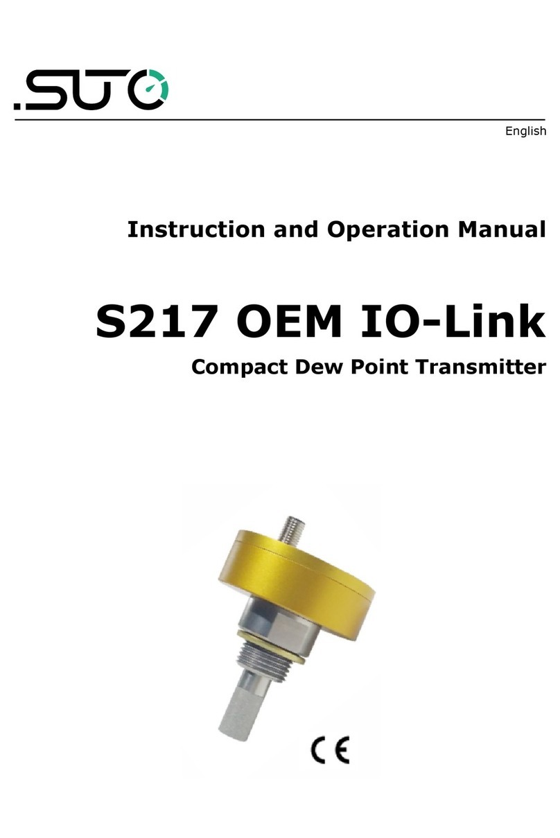
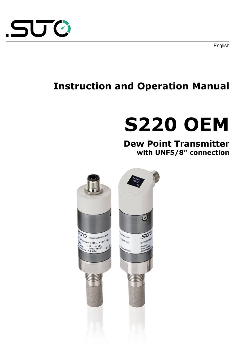
SUTO S020 Manual

English
Instruction and Operation Manual
S020
Temperature Transmitter

Dear Customer,
Thank you for choosing our product.
The operating instructions must be read in full and carefully observed
before starting up the device. The manufacturer cannot be held liable
for any damage which occurs as a result of non-observance or non-
compliance with this manual.
Should the device be tampered with in any manner other than a
procedure which is described and specified in the manual, the warranty
is cancelled and the manufacturer is e empt from liability.
The device is destined e clusively for the described application.
SUTO offers no guarantee for the suitability for any other purpose.
SUTO is also not liable for consequential damage resulting from the
delivery, capability or use of this device.
2 S020

Table of contents
1 Safety Instructions......................................................................4
2 Registered Trademarks................................................................6
3 Application.................................................................................7
4 Features....................................................................................7
5 Technical Data............................................................................7
5.1 General................................................................................7
5.2 Electrical Data.......................................................................7
5.3 Output Signals......................................................................8
5.4 Accuracy .............................................................................8
6 Dimensional Drawing...................................................................8
7 Determination of the Installation Point...........................................8
8 Installation ................................................................................9
8.1 Installation Requirements.......................................................9
8.2 Installation Procedure ...........................................................9
8.3 Electrical Connection ...........................................................10
9 Signal Outputs..........................................................................11
10 Optional Accessories................................................................11
10.1 Compression Fitting ..........................................................11
11 Calibration..............................................................................11
12 Maintenance...........................................................................11
13 Disposal or Waste....................................................................11
S020 3

Safety Instructions
1 Safety Instructions
Please check if this instruction manual accords to the
product type.
Please observe all notes and instructions indicated in this
manual. It contains essential information which have to be
observed before and during installation, operation and
maintenance. Therefore this instruction manual has to be read carefully
by the technician as well as by the responsible user / qualified
personnel.
This instruction manual has to be available at the operation site of the
temperature transmitter at any time. In case of any obscurities or
questions, regarding this manual or the product, please contact the
manufacturer.
ARNING!
Compressed air!
Any contact with quickly escaping air or bursting
parts of the compressed air system can lead to
serious injuries or even death!
•Only use pressure tight installation material.
•Avoid that persons get hit escaping air or bursting parts of the
instrument.
•The system must be pressureless during maintenance work.
ARNING!
Voltage used for supply!
Any contact with energized parts of the product, may
lead to a electrical shock which can lead to serious
injuries or even death!
•Consider all regulations for electrical installations.
•The system must be disconnected from any power supply during
maintenance work.
•Any electrical work on the system is only allowed by authorized
qualified personal.
4 S020

Safety Instructions
ATTENTION!
Permitted operating parameters!
Observe the permitted operating parameters, any
operation exceeding this parameters can lead to
malfunctions and may lead to damage on the
instrument or the system.
•Do not e ceed the permitted operating parameters.
•Make sure the product is operated in its permitted limitations.
•Do not e ceed or undercut the permitted storage and operation
temperature and pressure.
•The product should be maintained and calibrated frequently, at
least annually.
General safety instructions
•It is not allowed to use the product in e plosive areas.
•Please observe the national regulations before/during installation
and operation.
Remarks
•It is not allowed to disassemble the product.
•Always use spanner to mount the product properly.
ATTENTION!
Measurement values can be affected by malfunction!
The product must be installed properly and
frequently maintained, otherwise it may lead to
wrong measurement values, which can lead to
wrong results.
•Do not e ceed the ma imum operation temperature at the sensors
tip.
•Avoid condensation on the sensor element as this will affect the
accuracy enormously.
S020 5

Safety Instructions
Storage and transportation
•Make sure that the transportation temperature of the device is
between -40 ... +90°C.
•For transportation it is recommended to use the packaging which
comes with the device.
•Please make sure that the storage temperature of the device is
between -40 ... +90°C.
•Avoid direct UV and solar radiation during storage.
•For the storage the humidity has to be <90%, no condensation.
2 Registered Trademarks
SUTO®
Registered trademark of SUTO iTEC
MODBUS®
Registered trademark of the Modbus Organization, Hopkinton, USA
6 S020

Application
3 Application
The S020 Temperature Transmitter is a sensor which is designed to
measure the temperature of liquid, vapour, compressed air and gases
within the permissible operating parameters. These parameters can be
found in the Technical Data section.
The S020 Temperature Transmitter is not developed to be used in
e plosive areas. For the use in e plosive areas please contact the
manufacturer.
The S020 Temperature Transmitter is mainly used in compressed air
systems in an industrial environment.
4 Features
•Easy installation in compressed air systems.
•Measure the inlet / outlet temperature of dryers.
•Measure the outlet temperature of compressors.
5 Technical Data
5.1 General
Parameters Standard unit temperature: °C
Principle of measurement Resistance change
Sensor PT 1000, class A
Measuring medium Non-corrosive gases
Measuring range -50 °C ... +200 °C
Ambient temperature -40 °C ... +90 °C
Tube material Stainless steel 1.4571
Protection class IP65
Dimensions See dimensional drawing below
Weight 80 g
5.2 Electrical Data
Power supply 16 ... 30 VDC
S020 7

Technical Data
5.3 Output Signals
Analogue output 4 ... 20 mA, 2 wire loop powered
5.4 Accuracy
Accuracy 0.5 % of reading + 0.2 % FS
6 Dimensional Drawing
7 Determination of the Installation Point
In order to maintain the accuracy stated in the technical data, the
Temperature Transmitter must be installed correctly. The sensor tip
should not contact the inner wall of the pipe, which will lead to wrong
measurement values. For further instructions, please read the ne t
chapter carefully.
Please consider that enough space e ists at your site for a adequate
installation as described in this manual.
ATTENTION!
rong measurement is possible, if the Temperature
Transmitter is not installed correctly.
•Careful attention must be paid to the insertion depth of the
Temperature Transmitter. Not less than 2/3 of the Temperature
Transmitter shaft should be inside of the pipe.
•The sensor tip may not contact the inner wall of the pipe.
•The Temperature Transmitter is for indoor use only! At an outdoor
installation, the Temperature Transmitter must be protected from
solar radiation and rain.
•It is strongly recommend not to install the Temperature
Transmitter permanently in wet environment as it e ists usually
right after a compressor outlet.
8 S020

Installation
8 Installation
Please make sure that all components listed below are included in your
package.
Qty Description Item No.
1 S020 Temperature Transmitter S693 0003/ S693 0004
1 Depending on orders:
M12 plug or M12 cable
Plug: C219 0059
Cable: A553 0104/A553 0105
1 Instruction manual No P/N
8.1 Installation Requirements
To install the temperature transmitter a nozzle and a compression fitting
is needed.
•The inner thread has to be G ½”.
•The diameter of the hole must be ≥ 6 mm, other wise the shaft
can not be inserted.
8.2 Installation Procedure
The following steps e plain the procedure of an appropriate installation.
Installation of the instrument
1. Screw the compression fitting tightly to the nozzle of the pipe.
2. Loosen the nut of the compression fitting.
3. Move the temperature transmitter slightly through the
compression fitting into the pipe.
◦Not less than 2/3 of the Temperature Transmitter shaft should
be inside of the pipe.
◦The sensor tip may not contact the inner wall of the pipe.
4. Screw the nut of the compression fitting.
Removal of the instrument
1. Loosen the nut of the compression fitting.
2. Pull out the temperature transmitter slowly.
S020 9

Installation
8.3 Electrical Connection
The Temperature Transmitter is equipped with a M12 connector plug.
The cable is connected to the transmitter using the M12 connector.
Please refer to connection diagram below.
ATTENTION!
Do not screw the M12 plug using force. Otherwise, it
may damage the connecting pins.
10 S020

Signal Outputs
9 Signal Outputs
The temperature transmitter has an analog output range of 4 ... 20 mA.
It is a 2 wire loop powered analog output. This output is scaled to:
•4 mA = -50 °C
•20 mA = +200 °C
10 Optional Accessories
10.1 Compression Fitting
There are different types of compression fittings available:
•compression fitting 6mm, G1/2”, PTFE ring, 0.6 MPa
•compression fitting 6mm, G1/2”, metal ring, 1.6 MPa
11 Calibration
It is recommended to calibrate respectively adjust the Temperature
Transmitter annually. For this please contact the manufacturer.
12 Maintenance
To clean the Temperature Transmitter and its accessories it is
recommended to use moist cloth only
13 Disposal or aste
Electronic devices are recyclable material and do not
belong in the household waste.
The Temperature Transmitter, the accessories and its
packings must be disposed according to your local
statutory requirements. The dispose can also be carried by
the manufacturer of the product, for this please contact
the manufacturer.
S020 11

SUTO iTEC GmbH
Grißheimer Weg 21
D-79423 Heitersheim
Germany
SUTO iTEC (ASIA) Co., Ltd.
Room 10, 6/F, Block B, Cambridge Plaza
188 San Wan Road, Sheung Shui, N.T.
Hong Kong
Tel: +49 (0) 7634 50488 00
Email: [email protected]
Website: www.suto-itec.com
Tel: +852 2328 9782
Email: [email protected]
Website: www.suto-itec.com
All rights reserved © Modifications and errors reserved
S020_im_en_2023-1-SUTO
12 S020
This manual suits for next models
2
Table of contents
Other SUTO Transmitter manuals
Popular Transmitter manuals by other brands

Metal Samples Company
Metal Samples Company CorrTran MV MS2900L Operator's manual

RIDGID
RIDGID NAVITRACK Operator's manual

Emerson
Emerson Rosemount 3051 Quick installation guide

Spectra
Spectra FW V1.3 User manuals

M-system
M-system M5PA-CA-R instruction manual

Monacor
Monacor JTS RU-G3TB/5 instruction manual

DLO
DLO TransDock micro quick start guide

PR
PR PRetrans 5131 manual

Honeywell
Honeywell XNX Safety manual

BBC Bircher
BBC Bircher Swissdoor RFGate 3.1 370046A Original operating instructions

Becker
Becker Centronic SunWindControl SWC241-II Assembly and operating instructions

JTS
JTS PT-920B instruction manual