MEASURE OF SUCCESS
USER INSTRUCTIONS
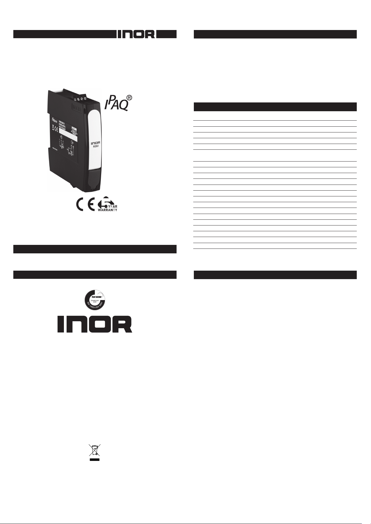
PC-programmable
2-wire Transmitter
for Pt100 Input
The user instruction must be read prior to adjustment and/or installation.
All information subject to change without notice.
4004716601 2016-02
GENERAL INFORMATION
IPAQ R202 is a low cost, non-isolated, easy-to-use 2-wire temperature
transmitter for Pt100 input intended to be used in industrial environment.
IPAQ R202 is designed to be mounted on a 35 mm DIN Rail.
The transmitter is congured from a PC via a USB port, connected via the
INOR USB Interface, by using the ConSoft program.
All necessary hardware and software for conguration are included in the
ICON Conguration Kit, 70CFGUS001.
R202 DATA (short form)
Input Pt100 3-wire connection
Pt100 (IEC 60751,
α
=0.00385) -200 to +850 °C / -328 to +1562 °F
Adjustments - Zero Any value within range limits
Adjustments - Minimum span 20 °C / 36 °F
Output 4-20 mA, temperature linear
Sensor failure indication Upscale (≥21.0 mA) or downscale (≤3.6 mA)
NAMUR Compliance Current limitations and failure currents acc.
to NAMUR NE 43
Response time 0.13 to 54 s, adjustable ltering level
Ambient temperature
Storage and operation -40 to +85 °C / -40 to +185 °F
Galvanic isolation No
Power supply 6 to 35 VDC
Accuracy Max. of ±0.1 °C / ±0.2 °F or ±0.1 % of span
Sensor error correction Via two-point correction
Runtime counter Hour counter for elapsed operational time
Mounting DIN rail acc. to EN 60715 / EN 50022, 35 mm
Factory settings
Input Pt100 3W, 0 to 100 °C
Output 4 to 20 mA
Filtering level Response time 0.9 s
Sensor failure indication Upscale (≥21.0 mA)
CONFIGURATION
Before making a conguration of IPAQ R202 you need to do
following:
1. Install the conguration software ConSoft and drivers for the
INOR USB communication interface on a PC.
2. Connect the USB Interface to a free USB port of your PC and
wait for automatic installation of the USB Interface.
Please refer to the installation guide for ConSoft for detailed
installation instructions.
Required versions of conguration software:
ConSoft, 3.1.0 or higher
USB Interface, rmware 1.2.06 or higher
Connections:
PC to Interface: through USB type A to USB type B connection cable
Interface to transmitter: Mini USB type B to Mini USB type B cable
Conguration procedure:
1. Connect the transmitter to the PC via the USB Interface, LED indicator
“DEV” on the USB Interface becomes green.
Conguration can be performed with or without connected power
supply to the transmitter.
2. In ConSoft, click on the “Read” button. The software will recognize
the connected transmitter and open the conguration window.
3. In the “C202/R202” conguration window you can edit:
a. Measuring range in three different engineering units
b. Upscale or downscale action at sensor errors
c. Compensation for known sensor errors
d. TAG-number
4. The selected conguration is downloaded to the transmitter by
clicking the button “Write”, when the data transfer is complete,
the transmitter begins using the new parameters directly.
MEASURE OF SUCCESS
This product should not be mixed with other kind of scrap, after usage.
It should be handled as an electronic/electric device.
www.GlobalTestSupply.com
Find Quality Products Online at: sales@GlobalTestSupply.com


