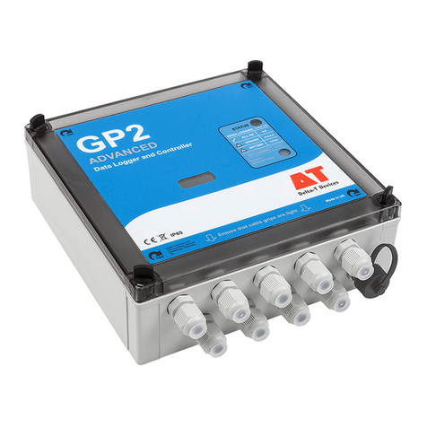
Metal Samples MS3500E User manual


Table of
Contents
I. Introduction ............................................................................................................................................ 1
A. General Description ................................................................................................................. 1
B. Principles of Operation ............................................................................................................ 1
C. Technical Specifications ........................................................................................................... 3
II. Start Up and Operation.......................................................................................................................... 4
A. Receiving the MS3500E/MS3510E Data Logger ...................................................................... 4
B. Start Up .................................................................................................................................... 4
1. Probe Connection....................................................................................................... 4
2. Current Loop Connection (for the MS3510E model) ................................................. 5
3. Power Up.................................................................................................................... 6
a. Safe Area Usage .............................................................................................. 6
b. Hazardous Area Usage .................................................................................... 6
c. Battery Replacement....................................................................................... 7
C. Setup and Operation................................................................................................................ 10
1. Select Probe .............................................................................................................. 11
a. Enter New Probe................................................................................................... 11
b.Select Existing Probe............................................................................................. 12
c.Delete Existing Probe ............................................................................................ 12
2. Measure Probe........................................................................................................... 13
3. Recall Readings........................................................................................................... 14
4. File Transfer................................................................................................................ 15
a. Measurement Data File Transfer............................................................................ 15
b. Upload/Download Config ...................................................................................... 18
5. Comm./Loop .............................................................................................................. 19
6. Config Setup ............................................................................................................... 20
a. Date & Time............................................................................................................ 20
b. Alarm Time ............................................................................................................ 21
c. Display Power Down Time ...................................................................................... 22
d. Unit ID.....................................................................................................................22
7.Display Disabled ......................................................................................................... 24
8.Status.......................................................................................................................... 25
9. Error Messages............................................................................................................ 25
D. Maintenance.......................................................................................................................... 29
1.Testing the MS3500E/MS3510E with the Meter Prover.......................................... 29
E. Troubleshooting ..................................................................................................................... 30
III. Service and Warranty Information...................................................................................................... 31
A. Warranty ................................................................................................................................ 31
B. Obtaining Service and Returning the Instrument for Repair ................................................. 31
C. Instrument Repair Form......................................................................................................... 32
Appendix A – Revision History ................................................................................................................. 33
Appendix B – Hazardous area certification details .................................................................................. 34
Appendix C – Control Drawing (Hazardous Area Wiring Diagram) .......................................................... 36


1
I. Introduction
A. General Description
The MS3500E/MS3510E is a battery powered, corrosion meter capable of measuring and storing data
from all types of electrical resistance (ER) corrosion probes. The instrument is light weight,
microprocessor-based, and features a simple, menu-driven interface using a keypad and a graphical LCD
display.
Corrosion rate measurements are made using the electrical resistance method. Essentially, the instrument
measures the resistance of the probe element which changes over time, as metal loss occurs. The rate of
change is directly proportional to corrosion rate. This method finds a wide variety of applications since it
can be used in conductive and nonconductive environments such as petroleum, chemical, water, soil, or
even atmosphere. The new high-resolution measurement of the MS3500E/MS3510E detects smaller
increments of metal loss, providing faster response than traditional ER instruments.
After taking a reading, the instrument displays metal loss in mils. All stored readings are automatically
time and date stamped. Readings are stored to non-volatile Flash memory which retains data without the
need for a battery backup.
The MS3500E/MS3510E High Resolution ER Data Logger can store more than 100000 readings. Stored
data can be downloaded directly to a USB Flash (“jump”) drive or Bluetooth compatible devices via
Bluetooth. Data can be opened and charted using the provided CDMS software, or it can be imported into
any standard data analysis (spreadsheet) program such as Microsoft Excel. Data can also be reviewed and
charted on the instrument’s LCD display for quick reference.
B. Principles of Operation
The MS3500E/MS3510E High Resolution ER Data Logger operates on the Electrical Resistance (ER)
technique and is used in conjunction with an ER probe. The ER probe utilizes a resistive sensing
element manufactured from the material of interest (or a close approximation) which is exposed to a
corroding environment. This is called the Exposed or Corroding Element. The resistance of the
Exposed Element is directly related to its thickness, so as the element corrodes the resulting loss of
metal causes a proportional
increase in
the element’s resistance. The probe also contains an internal
Reference Element which is used to compensate for the influences of temperature on the Exposed
Element.
The MS3500E/MS3510E High Resolution ER Data Logger is designed to work with any standard ER
probe, but it is recommended that Cylindrical and Large Flush type probes be used to ensure optimum
performance. Their physical design places the Reference Element in closer proximity to the Exposed
Element compared to other probe types, providing more effective temperature compensation and
thus reducing the effects of thermal noise.

2
Because they are designed to corrode, ER probes are sacrificial in nature. Each ER probe will have a
finite life that is based on the element thickness. ER probes are available in several geometries and
thicknesses designed to suit a wide variety of applications. Table 1 lists the common ER element
options available from Metal Samples and the effective life of each.
Element Type Compatibility Thickness
Probe Life
(Span)
Tubular Loop Compatible
4 2
8 4
Wire Loop Compatible
40 10
80 20
Flush (Small) Compatible
4
2
8
4
20
10
Cylindrical Preferred
10
5
20
10
50
25
Flush (Large) Preferred
5
2.5
10
5
20
10
40
20
Table 1. Standard ER Probe Elements
The MS3500E/MS3510E High Resolution ER Data Logger measures an ER probe utilizing a high-
resolution, 16-bit measurement. This allows the unit to detect much smaller amounts of metal loss,
thus responding faster to corrosion events and upsets. At 16-bit resolution the MS3500E/MS3510E
ER Data Logger can measure metal loss amounts as small as 0.004% of the probe life. For highly
sensitive probes such as the 5-mil large flush shown above, that results in a detection limit of less
than one angstrom.

3
C. Technical Specifications
Model
MS3500E - Basic Model
MS3510E - Basic Model + 4-20mA Current Loop Output
MS3520E - Basic Model + Bluetooth
MS3530E - Basic Model + RS-232 Serial Communication
MS3540E - Basic Model + RS-232 & 4-20mA Current Loop Output
Physical Data
Instrument Weight (w/ boot):
5.75 lbs. (2.61 kg)
Total Weight w/ Case & Accessories:
7.75 lbs. (3.52 kg)
Instrument Dimensions:
MS3520E: 12.00“H x 5.55” W x 7.61” D (30.48cm x 14.10cm x 19.33cm)
All Other: 5.50“H x 5.55” W x 7.61” D (13.97cm x 14.10cm x 19.33cm)
Case Specifications:
NEMA 4X / IP66 - stainless steel
Mounting Specifications:
Direct probe Mount
Operating Temperature:
-40° to 158°F (-40° to 70°C)
Storage Temperature:
-40° to 185°F (-40° to 85°C)
Operating Humidity Range:
30% - 95%
Performance Data
Measurement Type:
ER measurement using any standard ER Probe Types
Preferred Probe Types: Cylindrical, Flush
Compatible probe types: Tube Loop, Wire Loop, Flush, Strip, etc.
Range:
0 - 65,535 probe life units (displayed as 0.00 to 1000.00 PLU’s in
0.04 increments)
Resolution:
0.0015% of Probe Life
Repeatability:
± 0.2% of Full Scale
Electrical Data
Power Requirements:
7.2V lithium Battery pack
Nominal Probe Cable Distance:
30 ft. (10 m)
Download Method:
To certified Bluetooth enabled devices or directly to USB Flash
drive (Metal Samples Flash drive required for use in hazardous
areas)
Hazardous Location Certifications –IntrinsicSafety
See Appendix B
Included Accessories
Meter Prover, Operation Manual, Corrosion Data Management Software
OptionalAccessory Items (Ordered Separately)
Certified Data Transfer Unit (required for transferring data in a hazardous area)

4
II. Start-up and Operation
A. Receiving the MS3500E/MS3510E High Resolution ER Data Logger
Check the MS3500E/MS3510E High Resolution Data Logger for any shipping damage when it is first
received. When the unit is unpacked, verify that the following items are included:
•Data Logger
•Battery pack (Shipped Separately)
•Meter Prover
•User’s Manual
•Current Loop Cable (MS3510E Model Only)
In the event of shipping damage, quantity shortage, or missing items, it is recommended that the
event is documented immediately and that digital photographs are taken. Any shortages or
missing items should be reported to Metal Samples immediately. In the event of shipping
damage, a claim should be opened with the responsible carrier.
B. Start-Up
CAUTION: Using this product in any way other than that specified within this manual may impair the
intrinsic safety protection.
Start-up of the MS3500E/MS3510E Data Logger involves the following steps:
1. Port Details and Probe Connection
2. Current Loop Connection (MS3510E Model Only)
3. Power-Up
4. Setup and Operation
1. Probe Connection
CAUTION: Using this product in any way other than that specified within this manual may impair the
intrinsic safety protection.
When selecting a location to mount the data logger it is important to consider the surrounding
environment. To ensure proper operation:
•Do not mount the transmitter in a location that exceeds its operating temperature.
•Avoid mounting the transmitter near sources of strong electrical noise.
•Ensure that there is sufficient clearance for installation and to open the transmitter cover
afterwards.

5
a. Remote Mounting
The unit is designed to mount remotely. The data logger is connected to the ER probe via the probe
extension cable. When possible, the data logger should be mounted within 10’ (3m) of the probe to
keep the probe cabling short and minimize signal degradation.
2. Current Loop Connection (for the MS3510E model)
To setup current loop communication, refer to the Control Drawing (Hazardous Area Wiring
Diagram), found in Appendix C: Control Drawing on page 36.
OR
a. In the Safe Area only, connect the external current loop cable (shipped with the
instrument) to either:
-Certified Safety Barrier (EEx ia) IIC Typical of MTL 7787+
-Certified 4-20mA Repeater Power Supply (EEx ia) IIC Typical of MTL 5541+.
b. Connect the 2-pin connector from the external current loop cable to the instrument’s
4-20mA current loop port.
c. Current measurements will be explained in the “Comm./Loop” section on Page 19.

6
3. Power-Up
The unit is supplied with a battery pack in a separate package. Install the battery pack before starting
the product. The instrument can be powered up by pressing the ‘ON’ button on the keypad. The start-
up screen with the Metal Samples logo will appear on the screen; the start-up screen confirms the
software version currently running and the SD card status. The keypad switch layout is shown below.
a. Safe Area Usage
The MS3500E/MS3510E High Resolution Data Logger is approved for use in hazardous areas
but can be used in non-hazardous areas as well.
The cells in the battery pack must be replaced only in a safe area and it should be replaced
with batteries of the same make and model.
b. Hazardous Area Usage
Refer to Appendix B for details.
Power On Button
Display Window
USB Port
Menu / Enter Button

7
c. Battery Replacement
WARNING:
•Do not mix old and new batteries. Equipment is intended for use only with Xeno Energy model
XL-205F and Tadiran model TL-5930 cells. Use of any other battery in this device may impair
intrinsic safety.
•Do not mix batteries of different types (such as alkaline and lithium.)
•The cover screw is used to prevent unauthorized tampering of the batteries and is required to
ensure intrinsic safety.
•Do not over-tighten the cover screw, as this may damage the instrument case.
To remove the battery pack from the Instrument:
1. Open the front door of the enclosure by unscrewing and unlatching the four latches securing
the front door.
2. Unscrew the two thumb screws securing the front panel. Open the front panel.

8
3. Disconnect the battery cable connection, by pressing down on the locking tab and pulling.
4. Unlatch and remove the battery holder assembly from the mounting plate DIN rail.

9
Replace battery cells:
Follow the previous instructions ‘To remove the battery pack from the Instrument’ and move the
battery
pack to a safe location.
WARNING: ENSURE BATTERY PACK IS MOVED TO SAFE LOCATION BEFORE CONTINUING.
FAILING TO DO SO MAY IMPAIR INSTRINSIC SAFETY.
1.
With the battery pack in a SAFE location, remove the 4
Tamper
Resistant Torx Screws from the
battery pack.
Remove the
battery pack cover.
2.
Remove the battery cells from the pack. Check that
new batteries are of the same type
as those
removed.
3.
Insert the new batteries into the pack, ensuring that
the
direction matches the battery
pack.
4.
Replace the battery pack cover
and screw in the 4
Tamper
Resistant Torx Screws until snug.
DO NOT OVERTIGHTEN.
Replace battery Pack:
Follow the instructions to return the battery pack
To return the battery pack with replacement:
1.
Reinstall the battery pack within the instrument enclosure by latching the battery pack
assembly to the mounting plate DIN rail.
2.
Reconnect the battery pack cable by pushing the battery cable and the
power cable
connectors together until they lock.
3.
Close the front panel and tighten the 2 thumb screws.
4.
Close the enclosure door, latch all 4 of the latches to the door, then tighten the 4 screws to
secure the latches.

10
C. Setup and Operation
MAIN MENU
The MS3500E/MS3510E allows you to measure metal loss and corrosion rate. This section
describes the functions that display on the Main Menu:
The Start-Up display shows the data logger’s unit ID at the top of the screen.
It also shows the recent probe data in probe life units with a range of 0 to 65535, metal loss in mils,
and corrosion rate in mils per year.
Probe ID, probe type and probe life also displayed in the bottom of the screen. Current date and
time are displayed in the last line.
Press ‘MNU/ENT’ key on the keypad to display the menu screen.
a. MENU DISPLAY
Review this section which describes the functions that display on the Main Menu.
METAL SAMPLES
Unit ID: 0000000001
DATA (PLU): 32075
METAL LOSS: 4.89 mils
CR: 21.141685 mpy
PID: 9991
TYPE: WIRE PL: 10.00
04/01/2020 14:30
1. PROBE SELECTION
2. MEASURE PROBE
3. RECALL READINGS
4. FILE TRANSFER
5. COMM./LOOP
6. CONFIG SETUP
7. STATUS

11
Select the functions by using the UP/DOWN arrow keys to navigate and pressing ‘MNU/ENT’ key to
select an option. Pressing ‘<-’ will return the selection to the previous screen.
1. PROBE SELECTION
Select the ‘PROBE SELECTION’ option from the main menu to access the probe selection menu.
You can enter a new probe, delete a probe, or select an existing probe from this section.
a. ENTER NEW PROBE
To enter the ID of a new probe, navigate to the ‘ENTER NEW PROBE’ option by using the
UP/DOWN arrow keys, and press MNU/ENT key to select the option; the next screen allows you
to enter the probe ID number and the probe type.
1. Enter the Probe ID using the Up/Down arrow Keys. (Use the Up/Down arrows to scroll
between alphanumeric characters. Use the Right/Left arrows to advance to the next
character or go back to the previous character.) When a 7-digit Probe ID is entered the
cursor automatically advances to the Probe Type field.
2. Use the Up/Down arrows to select the Probe Type. Use the Right arrow to advance to
the Probe Life field.
3. Enter the Probe Life using the up/Down arrow keys.
4. Press ENTER.
PROBE SELECTION
1. ENTER NEW PROBE
2. DELETE EXISTING
9991 , WI,10.00 – A
9992 , TU,10.00
9993 , CL,10.00
9994 , MC,10.00

12
b. SELECT EXISTING PROBE
The Probe Selection menu displays the four probe IDs currently in memory. Select the probe you
wish to take a measurement with by using the UP/DOWN arrow keys and press ‘MNU/ENT’ key.
Current selected probes /active probes will be displayed with an ‘A’ symbol at the end of the probe
ID line.
c. DELETE EXISTING PROBE
It is occasionally necessary to remove the ID of a probe from memory, for example:
oWhen the memory bank is full
oWhen a probe is no longer used
To delete the ID of a probe in memory, select Probe Selection Menu from the Main Menu. Select
DELETE EXISTING.
PROBE ID : 9991
PROBE TYPE : WIRE
PROBE LIFE : 10.0
PROBE SELECTION
3. ENTER NEW PROBE
4. DELETE EXISTING
9991 , WI,10.00 – A
9992 , TU,10.00
9993 , CL,10.00
9994 , MC,10.00

13
1. Press the Down arrow to select the probe ID which needs to be deleted.
2. Press ‘ENT/MNU’ key. The selected probe ID will be deleted from memory and the Probe
Selection menu.
2. MEASURE PROBE
Select a probe before you run the function
To run ‘MAKE MEASUREMENT’ you must select a probe from memory first. See ‘SELECT
PROBE’ from the Main menu.
To make a measurement manually, select ‘MEASURE PROBE’ in the Main Menu. Ensure that
the probe connected to the data logger is selected as the active probe before using this
function. The display changes as below and the data logger measures the probe. The probe
ID, probe type, and probe life of the current measuring probe is displayed at the bottom of
the screen.
DELETE EXISTING
9991 , WI, 10.00 – A
9992 , TU, 10.00
9993 , CL, 10.00
9994 , MC, 10.00
2. MEASUREMENT
MEASURING . . .
ID: 9991
TYPE: WIRE PL:10.00

14
The measured values will be displayed as shown below.
The measured value can be saved by pressing the ‘MNU/ENT’ key.
Take another measurement by pressing the ‘up’ arrow key.
3. RECALL READINGS
Selecting ‘RECALL READINGS’ in the main menu will allow you to display the last 7 readings of
the probe selected. Use the up/down arrow keys to navigate to the desired probe ID and
press the ‘MNU/ENT’ to select it.
The readings will be displayed as shown below. To exit the menu, press the left arrow key.
2. MEASUREMENT
READING: 32767
M. LOSS: 5.00 mils
CHECK: 4798
ID: PROBE1
TYPE: WIRE PL:10.00
^: MEASURE ENT: SAVE
LAST READING . .
32025, 04/01/2020, 12:5
32017, 04/01/2020, 10:5
32091, 04/01/2020, 09:5
32091, 04/01/2020, 08:5
32064, 04/01/2020, 07:5
32083, 04/01/2020, 06:5
32007, 04/01/2020, 05:5
RECALL READINGS
9991 , WI, 10.00 – A
9992 , TU, 10.00
9993 , CL, 10.00
9994 , MC, 10.00
PRESS ENTER TO SELECT

15
If there are no readings saved for the selected probe this screen will appear. Press the left arrow key to exit.
4. FILE TRANSFER
Selecting ‘FILE TRANSFER’ from main menu screen will display the file transfer screen as
below.
a. MEASUREMENT DATA FILE TRANSFER
To transfer probe readings, insert the USB storage device into the USB port of the data logger. Use
the UP/DOWN arrow keys to navigate to the probe ID you wish to transfer or ‘ALL FILES’ and press
‘MNU/ENT’ to select it. The data will be transferred to the USB storage device. The following screens
show the process of a successful file transfer. For information on potential errors see the Error
Messages section on page 25.
FILE TRANSFER
9991 , WI,10.00 – A
9992 , TU,10.00
9993 , CL,10.00
9994 , MC,10.00
ALL DATA FILES
CONFIG UPLOAD/DOWNLOAD
NO DATA AVAILABLE

16
ACCESSING USB
Step – 1
FLASH DRIVE FOUND
Step – 2
Checking DIR . . .
This manual suits for next models
4
Table of contents
Other Metal Samples Data Logger manuals

