berlinger SmartSystem SHIP L User manual

SmartSystem SHIP L Datalogger
Operators
Manual

Draft version 02 Operatots Manual / SmartMonitor SHIP L page 2 of 26
Table of Contents
1 Safety instructions.......................................................................................................................4
2 Quick Guide .................................................................................................................................5
2.1 Quick Start if configuration is already loaded on the device...................................................5
2.2 Quick Start if configuration needs first loaded to the device .................................................6
3 Device view and description........................................................................................................7
4 Display..........................................................................................................................................8
4.1 7-digit display...........................................................................................................................9
5 Multifunctional button ................................................................................................................9
6 Confirmation LED.......................................................................................................................10
7 Light sensor................................................................................................................................10
8 Humidity and pressure sensor...................................................................................................11
9 Tilt / Shock / Vibration...............................................................................................................11
10 Configuration.............................................................................................................................12
11 Start/Stop ..................................................................................................................................13
11.1 Start .......................................................................................................................................13
11.2 Stop........................................................................................................................................14
12 Start delay..................................................................................................................................15
12.1 Start SmartMonitor SHIP L with start delay...........................................................................15
12.2 Start SmartMonitor SHIP L with scheduled start...................................................................15
13 Usage Process............................................................................................................................16
13.1 Preparation............................................................................................................................16
13.1.1 Battery check.................................................................................................................16
13.1.2 Display check .................................................................................................................16
13.1.3 Housing check................................................................................................................16
13.2 Setup......................................................................................................................................17
13.2.1 Review/Check configuration..........................................................................................17
13.3 Start .......................................................................................................................................17
13.3.1 Start delay......................................................................................................................17
13.3.2 Scheduler Start ............................................................................................................18
13.4 Transit/Recording ..................................................................................................................18
13.4.1 Assess state of goods and information..........................................................................18
13.4.2 Manual Flight Mode.......................................................................................................18
13.5 Stop........................................................................................................................................18
13.5.1 Read out.........................................................................................................................18

Draft version 02 Operatots Manual / SmartMonitor SHIP L page 3 of 26
13.5.2 Upload data manually of read out data to Berlinger SmartView..................................19
13.5.3 Return device.................................................................................................................19
14 Where to place SmartMonitor SHIP L........................................................................................19
15 External Temperature Sensor....................................................................................................20
15.1 Connect an external sensor to SmartMonitor SHIP L device.................................................21
16 Connect SmartMonitor SHIP L device to SHIP S devices ...........................................................22
17 Troubleshooting.........................................................................................................................23
18 Disposal......................................................................................................................................25
19 Certification ...............................................................................................................................25
19.1 Specific Information for North America (FCC/ISED) ..............................................................25
20 Standards...................................................................................................................................26

Draft version 02 Operatots Manual / SmartMonitor SHIP L page 4 of 26
1Safety instructions
Intended use
Temperature
•Temperatures outside the operating range may damage the battery. For the
operating range, see the information in the technical data sheet.
IP Protection
•Limited protection against dust ingress and protection against splashing water from
all directions.
Air Pressure
•Excess pressure or vacuum can damage the device. Do not vacuum when used for air
cargo.
Mechanical force
•Avoid violent shocks and impacts.
Microwave
•Do not expose the device to microwave radiation (risk of battery explosion).
X-rays
•Avoid long-term exposure to X-rays (risk of damage to the device).
Battery
•The battery cannot be removed or replaced. SmartMonitor SHIP L device has a
rechargeable Non–lithium NiMH battery.
•Risk of fire or explosion if the battery is replaced by an incorrect type
•Risk of explosion if the battery is disposed of in a fire or hot oven
•Leaving the battery in an extremely high temperature surrounding environment can
result in an explosion or leakage
•Do not subject battery to extremely low air pressure that may result in an explosion
or the leakage of flammable liquid or gas
Safe use
•Ordinary persons can install and operate the unit without taking any other safety
precautions.
Radio Equipment
•Cellular (LTE M1, NB–IoT, 2G), BLE

Draft version 02 Operatots Manual / SmartMonitor SHIP L page 5 of 26
2Quick Guide
2.1 Quick Start if configuration is already loaded on the device

Draft version 02 Operatots Manual / SmartMonitor SHIP L page 6 of 26
2.2 Quick Start if configuration needs first loaded to the device

Draft version 02 Operatots Manual / SmartMonitor SHIP L page 7 of 26
3Device view and description
No. Name Description
1Display Multi-information display
2USB-connector To charge the battery or download the data manually
3Confirmation/Status LED LED (small lamp) indicates if use of multifunctional
button was successful or not
4Cover for ext. sensor Protect plug for external sensor
5QR Code Contains the serial number for M2M
(Machine to Machine)
6 Serial number Serial number of the device
7Device Type Indicates which type of device you have
8Multifunctional button 1 x long press →Start the device
1 x short press →Info
3 x short press →loading profile
9 Light sensor Measure the light sensitivity
10 Humidity and atmos- Measure humidity and atmospheric pressure
pheric pressure sensor

Draft version 02 Operatots Manual / SmartMonitor SHIP L page 8 of 26
4Display
Icon Name Description
1Battery status Indicates the battery status
2Battery charging Indicates whether external power has been plugged in
3Alarm status Device indicates that there is no alarm violation
Device indicates that there is one or more alarm violation
4Logging Modus OFF →SmartMonitor SHIP L is ready to start
REC →SmartMonitor SHIP L is logging
→SmartMonitor SHIP L has stopped
57-digit display Information line (see more in section 7-digit display)
6External readout Device ready for readout via USB or Bluetooth
7 Warning Symbol Additional warning for function
8Cloud status Upload successful
Upload not possible
9Signal strength Cellular connection
Cellular signal available
No cellular signal available

Draft version 02 Operatots Manual / SmartMonitor SHIP L page 9 of 26
4.1 7-digit display
The 7-digit display gives additional information about the status, shipment or other data.
In normal logging operation it displays the temperature.
5Multifunctional button
SmartMonitor SHIP L device has one multifunctional button to operate.
•Long press to multifunctional button
One long press (> 5 sec.) to multifunctional button will start or stop the device.
•3 short press to multifunctional button
Three short press to the multifunctional button will start setup process
•1 short press to multifunctional button
One short press to the multifunctional button, device will show information on the display or
skip to the next information.
1 x long press →Start / Stop the device
3 x short press →Setup –Load configuration
1 x short press →Information

Draft version 02 Operatots Manual / SmartMonitor SHIP L page 10 of 26
6Confirmation LED
Device has an LED which gives an indication if the use of multifunctional button was successful or if a
task has been terminated.
7Light sensor
SmartMonitor SHIP L device has a built-in light sensor to monitor whether a transport box has been
opened and the light ratio has changed. That sensor can be enabled or disabled in the Berlinger
SmartView software (version 6.0 and higher).
Important:
Do not stick any label or tape over the light sensor.
1 x short white flash →Confirmation of an action or task
1 sec. green flash →“Cancel Message”
Short press has released too early.
Green blinking →when longpress is going on
1 x long green flash →Longpress was successful, multi-
functional button can be released
1 x long blue flash →Information about a BLE connection
1 x long red flash →Information about cancelling a status

Draft version 02 Operatots Manual / SmartMonitor SHIP L page 11 of 26
8Humidity and pressure sensor
SmartMonitor SHIP L has a built-in humidity and atmospheric pressure sensor which can be enabled
or disabled in the Berlinger SmartView software (version 6.0 and higher) configuration. The sensor is
located on the left side of the device.
Important:
Keep the white sensor protector clean
Do not remove the grey sensor protection
Do not press on the grey sensor protection
Do not stick any label or tape over the light sensor
The sensor shall not get in close contact with volatile chemicals such as solvents or other organic
compounds. Especially high concentration and long exposure must be avoided. Ketenes, Acetone,
Ethanol, Isopropyl Alcohol, Toluene, etc. are known to cause drift of the humidity reading.
9Tilt / Shock / Vibration
SmartMonitor SHIP L has a built-in motion sensor to record tilt, shock and vibration. The sensor is
positioned inside the device and is not visible from the outside.
Tilt, shock and vibration can be enabled or disabled in the Berlinger SmartView software (version 6.0
and higher) configuration.
No maintenance or service is required for this built sensor.

Draft version 02 Operatots Manual / SmartMonitor SHIP L page 12 of 26
10 Configuration
The configuration for the SmartMonitor SHIP L device can be defined via the Berlinger SmartView
software (version 6.0 and later).
SmartMonitor SHIP L can be ordered pre-configured with a customer desired configuration or with a
standard configuration.
If a new configuration is to be loaded, it is configured in the Berlinger SmartView software (version
6.0 and higher) and then assigned to the device.
To load a defined and assigned configuration, the multifunctional button on the SmartMonitor SHIP L
device must be pressed 3 times in quick succession.
The display starts showing after press quickly 3 times following screen:
Start screen Test screen Connection to Downloading Device is ready
Berlinger cloud configuration to start
Cellular symbol Cloud symbol
is blinking is blinking

Draft version 02 Operatots Manual / SmartMonitor SHIP L page 13 of 26
11 Start/Stop
11.1 Start
To start the device, press the multifunctional button once >5 seconds or as long till display shows
“SETUP” or the green LED lights for at least 2 sec.
The following information will be displayed on the screen. While the information “***START***” will
be displayed as a ticker, keep pressed the multifunctional button and hold the multifunctional button
for at least 5 seconds.
As confirmation the green LED will flash for at least 2 sec.
If no start delay is configured, the device goes directly into the Record modus and shows REC on
the display as confirmation that the device is recording.
The large indicator on the screen or shows directly if the device is in good or alarm situation.
The 7-segment displays the “CURRENT” temperature.

Draft version 02 Operatots Manual / SmartMonitor SHIP L page 14 of 26
11.2 Stop
To stop the device, press the multifunctional button once >5 seconds or as long till display shows
“STOP” or the green LED lights for at least 2 sec.
As soon as the device has stopped, the 7-segment display shows “STOP”.
Additionally, the Stop symbol will be shown .
As confirmation the LED will flash 3 times short.
Device will start now the synchronisation process by uploading the remaining data.
Synchronisation in Synchronisation
progress “SYNC” completed “DONE”
Cloud Symbol
is blinking

Draft version 02 Operatots Manual / SmartMonitor SHIP L page 15 of 26
12 Start delay
For SmartMonitor SHIP L device you have the possibility to configure in Berlinger SmartView
software (version 6.0 and higher) with a start delay or with a scheduled start.
12.1 Start SmartMonitor SHIP L with start delay
If a start delay is configured a counter in minutes:seconds will start counting down to 00:00, after
that, the device starts and goes to the Record modus.
12.2 Start SmartMonitor SHIP L with scheduled start
If a scheduled start is configured a counter in days:hours:minutes (e.g., 01d14:32 = start in 1 day 14
hours and 32 sec) will be displayed on the 7-segment display.
By a short press to the multifunctional button, the information SCHEDULED START will show as ticker
on the display with above information about the time till the device will start recording.

Draft version 02 Operatots Manual / SmartMonitor SHIP L page 16 of 26
13 Usage Process
SmartMonitor SHIP L is mainly used for monitoring temperature sensitive products
throughout the supply chain. The device has various configuration options. The device states
are visualized below and described in more detail in the following chapters. The usage
process may vary depending on the configuration.
13.1 Preparation
13.1.1 Battery check
Check if the internal battery is charged and has enough capacity for the shipment. A device with a
fully charged battery can record with a logging interval of 10 minutes without GNSS (Global
Navigation Satellite System):
•at 5 °C: > 60 days at a transfer interval of 1h
•at 20 °C: > 60 days at a transfer interval of 1h
•at -20 °C: >60 days at a transfer interval of 6h
•at -30 °C: >60 days at a transfer interval of 6h
To check the battery level, press the multifunctional button once. The battery level is displayed as
follow:
Fully charged battery →Device can be used for shipment
Charged battery →Battery needs to be charged
Half charged battery →Battery needs to be charged
Low battery →Battery needs to be charged
Empty battery Battery needs to be charged
If nothing happens after pressing the multifunctional button, the battery needs to be charged.
If battery needs to be charged, connect it with a USB-C connector to a USB charger.
Important:
Charging the battery is only possible with a deactivated (switched off) SmartMonitor SHIP L device.
13.1.2 Display check
To check the display, press once short the multifunctional button, the display will show the status of
the device. (Check also chapter Maintenance)
13.1.3 Housing check
Check if the housing is not damaged and no label is attached over the light and humidity sensor.

Draft version 02 Operatots Manual / SmartMonitor SHIP L page 17 of 26
13.2 Setup
If no configuration is already loaded on the device, press the multifunctional button quickly
3 times .
→The configuration will be loaded. See chapter 5 multifunctional button
Configuration of device can be done with Berlinger SmartView software (version 6.0 and higher).
13.2.1 Review/Check configuration
To confirm that the loaded configuration is correct, check the configuration on the display by
pressing the multifunctional button once .
13.3 Start
To start the device, press the multifunctional button once (long press) for more than
5 seconds.
After that, the device will go to record mode and the display will show REC accordingly.
See chapter 5 multifunctional button
13.3.1 Start delay
If a start delay is configured, the device waits with start recording until start delay has expired. This is
indicated by a countdown in the display.

Draft version 02 Operatots Manual / SmartMonitor SHIP L page 18 of 26
The device cannot be stopped during start delay phase. This is a safety feature to prevent the device
from being stopped by mistake.
13.3.2 Scheduler Start
Device has the possibility to configure it with a scheduled start via Berlinger SmartView software
(version 6.0 and higher).
13.4 Transit/Recording
As long as the device is in transit, it records the temperature (and other parameters if set) and
transmits the data at a predefined interval via the cellular network to Berlinger SmartView software
(version 6.0 and higher). When the device is in the aircraft (airborne), the SmartMonitor SHIP L
automatically turns off the cellular transmission for safety reasons.
The display shows the current temperature and informs via the hook or cross whether the alarm
parameters have been violated.
13.4.1 Assess state of goods and information
As long as the device is in Transit user has the possibility to asset state of the goods and get
information on the device display by pressing the multifunctional button once .
13.4.2 Manual Flight Mode
As soon as the device is in Aircraft (airborne ) the SmartMonitor SHIP L automatically turns off the
cellular transmission for safety reasons. Customer has also the possibility to set the device manually
to Flight mode (no data will be sent via cellular network after that manually action.
To set the device manually to flight mode, press the multifunctional button quickly 5 times .
13.5 Stop
To stop the device, the key must be pressed for at least 5 seconds (log press) . The lower
part of the display shows information about how long the multifunctional button must be pressed.
See chapter 5 multifunctional button
13.5.1 Read out
Once stopped the device at final destination automatically, it sends all measured data to Berlinger
SmartView software (version 6.0 and higher).
If after a shipment an automatically upload is not possible, the two icons Bluetooth and USB will
flash. In that case read out of measured data can be done manually via USB.
•Read out via USB:
Connect the device to a computer, device will start immediately with downloading the data
to your computer.

Draft version 02 Operatots Manual / SmartMonitor SHIP L page 19 of 26
•Read-out via Bluetooth:
Read out via Bluetooth will be possible with a later version
13.5.2 Upload data manually of read out data to Berlinger SmartView
To upload the manually read out data to Berlinger SmartView software (version 6.0 and higher) you
have two possibilities:
•Direct upload to Berlinger SmartView software (version 6.0 and higher):
Open Berlinger SmartView software (version 6.0 and higher), chose Device →Upload Data
File →Select the datafile to upload →confirm it by pressing Upload File(s)
•Via e-mail:
Send the read out datafile via e-mail to qtag-upload@smartview.berlinger.com
13.5.3 Return device
If the transport is complete and the data are uploaded to Berlinger SmartView software (version 6.0
and higher), the device can be used for the next shipment.
Before the device will be used for the next shipment, follow the instruction at chapter Maintenance.
If the unit was rented from Berlinger, return it to Berlinger in accordance with the RMA process.
14 Where to place SmartMonitor SHIP L
Berlinger recommends to place SmartMonitor SHIP L as close as possible to the product to be
monitored so that the temperature can be recorded as accurately as possible.
If temperature monitoring is done with an external sensor, the external sensor should be as close as
possible to the product to be monitored and the SmartMonitor SHIP L can be mounted on the outer
cover.
Important:
If SmartMonitor SHIP L is mounted on the outer cover, Berlinger recommends securing the device so
that it cannot be damaged.
The cable of the external sensor should be mounted in such a way that it does not interfere with the
handling of the transport or can be pulled off.

Draft version 02 Operatots Manual / SmartMonitor SHIP L page 20 of 26
15 External Temperature Sensor
Use only original Berlinger external sensors for SmartMonitor SHIP L.
Make sure that the sensor is properly connected to the device and the connector is secured
(tightened by hand). Do not tighten the connector with pliers or any other tool, otherwise the
connector may be damaged.
The cable must be attached to the shipment in such a way that it does not interfere with normal
transport.
Berlinger offers several types of external sensor as:
1.5 Meter Temperature Sensor
1.5 Meter Temperature/Humidity Sensor
Table of contents
Other berlinger Data Logger manuals
berlinger
berlinger Fridge-tag 3 User manual
berlinger
berlinger Q-tag CLm doc User manual
berlinger
berlinger Fridge-tag 2 User manual
berlinger
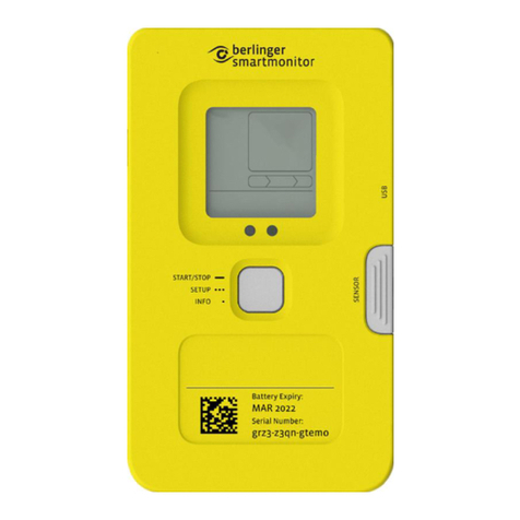
berlinger SmartSystem SITE L User manual
berlinger
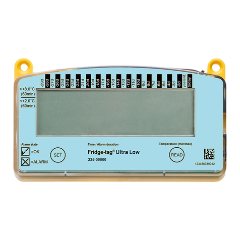
berlinger Fridge-tag Ultra Low User manual
berlinger
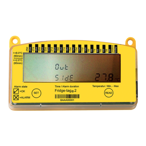
berlinger Fridge-tag 2 User manual

berlinger
berlinger Fridge-tag 2 Instruction Manual

berlinger
berlinger Fridge-tag 2 L Manual
berlinger
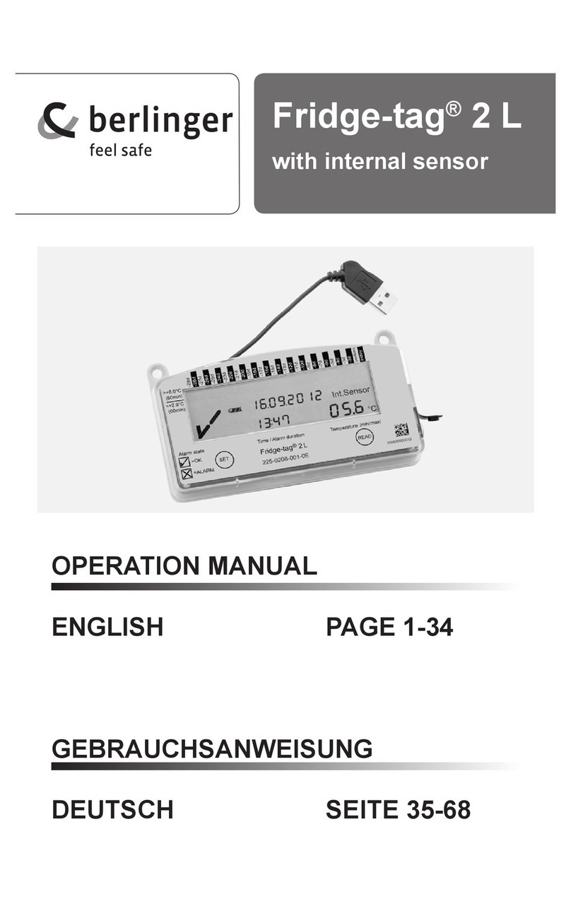
berlinger Fridge-tag 2 L User manual
berlinger
berlinger Fridge tag User manual
