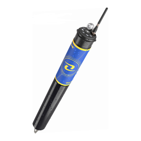
Primayer PrimeLog User manual

PrimeLog User Manual
Issue 6.1
Mai 2003
Primayer Limited
Primayer House
Parklands Business Park
Denmead
Hampshire
PO7 6XP
Telephone +44 (0) 23 9225 2228 Fax +44 (0) 23 9225 2235

UK Office:
Primayer Limited
Primayer House
Parklands Business Park
Denmead
Hampshire
PO7 6XP
England
Telephone: +44 (0)23 9225 2228 Fax: +44 (0)23 9225 2235
Malaysian Office:
Primayer Sdn Bhd
23 Jalan TPP 6/3,
Taman Perindustrian Puchong,
Section 6,
47100 Puchong,
Selangor DE,
Malaysia
Telephone: +603 8060 5225 Fax: +603 8060 5252
French Office:
Primayer France
1, rue Louis Juttet
69410 CHAMPAGNE AU MONT D’OR
France
Telephone: +33 (0) 4 72 19 10 62 Fax: +33 (0) 4 72 17 70 54
Primayer Limited reserves the right to amend any specification without notice. Primayer Limited will not be
responsible for any consequential damages arising from such changes, or from errors contained in any publication.
Copyright © Primayer Limited 1998, 2002
Windows 95®, Windows 98®, Windows Me®, Windows NT®, Windows 2000® and Windows XP®are registered
trademarks of Microsoft Corporation. All other trademarks are acknowledged.
Document Number: LXD 011/6.1

Table of Contents
PrimeLog User Manual
Contents
1. PrimeLog...............................................................................................................4
1.1. Introduction..........................................................................................................4
1.1.1. Features of logger range..........................................................................4
1.2. PrimeLog Type.....................................................................................................4
1.2.1. Model........................................................................................................4
1.2.2. Main features............................................................................................4
1.2.3. Logging features.......................................................................................4
1.2.4. Flow and pressure logging .......................................................................5
1.2.5. Special features........................................................................................5
1.3. System Description..............................................................................................6
1.3.1. Overview...................................................................................................6
1.3.1.1. Auxiliary battery unit...............................................................................7
1.3.1.2. Auxiliary Battery/Communications adaptor............................................8
1.4. Hardware Connections ........................................................................................9
1.4.1. Sealing......................................................................................................9
1.4.2. Polarisation...............................................................................................9
1.4.3. PrimeLog Input Connections....................................................................9
1.4.3.1. Digital Inputs..........................................................................................9
1.4.3.2. Internal Pressure Transducer ................................................................9
1.4.3.3. Analogue Inputs...................................................................................10
1.4.3.4. Communication Link ............................................................................10
1.4.3.5. Modem Connection..............................................................................10
1.5. Installation and Use...........................................................................................11
1.5.1. Logger Set Up ........................................................................................11
1.5.2. Logger Use.............................................................................................11
1.6. Interfacing..........................................................................................................12
1.6.1. Quadrina Insertion Meters......................................................................12
1.6.1.1. The Quadrina range.............................................................................12
1.6.1.2. Volumetric flow measurement..............................................................12
1.6.1.3. Probe calibration..................................................................................12
1.6.1.4. Logger Configuration ...........................................................................12
1.6.2. Other Flowmeters...................................................................................13
2. Appendices.........................................................................................................14
2.1. Appendix 1: Meter Scaling Tables....................................................................14
2.1.1. Kent Domestic, Helix & Master Meters...................................................14
2.1.2. Schlumberger Domestic & Helix Meters.................................................14
2.1.3. Socam Domestic & Helix Meters............................................................15
2.1.4. Supplementary Notes for Meter Scaling Tables.....................................15
2.1.4.1. Kent Meters:.........................................................................................15
2.1.4.2. Schlumberger meters:..........................................................................15
2.1.4.3. Socam meters:.....................................................................................16
2.2. Appendix 2: Specifications................................................................................17
2.3. Appendix 3: Safety.............................................................................................19
2.3.1. Airfreight Regulations applicable to PrimeLogs......................................19
2.3.1.1. Shipment of loggers in new condition..................................................19
2.3.1.2. Shipment of loggers with discharged batteries....................................19
2.4. Appendix 4: Modem Statutory Notices..............................................................20

PrimeLog
PrimeLog User Manual 4
1 PrimeLog
1.1 Introduction
PrimeLog is a family of advanced submersible dataloggers, designed specifically for
applications in the Water Industry. A typical range of applications includes:
•District, domestic and leakage flow monitoring
•Network analysis
•Pressure monitoring
•PRV monitoring
•Open channel flow
•Reservoir and borehole depth
The range of loggers offers single, two or four data input channels; this manual describes
operation in a general manner, thus some sections may not be applicable to particular loggers.
1.1.1 Features of logger range
Standard (non-modem) Logger 1F 1A 1P 2i 2 4 4i
Telephone (PSTN) Logger 1FM 1PM 2iM 2M 4M
Total number of channels 1 1 1 2 2 4 4
Number of bi-directional flow
channels 1 1 1 2 2
Number of analogue channels (for
transducer, voltage or current input) 1 1 2
Number of internal pressure channels 1 1 2
Pressure / analogue channel
accuracy (%) ±0.1 ±0.5 or
±0.1 ±0.1 ±0.1 ±0.1 ±0.1
1.1.2 Main features
•Single to four channel models
•Submersible to IP68
•Powered for five years (see note below)
•Extremely robust
•Fits in small locations
•Maintainable – can be disassembled
Please Note: The battery packs fitted to PrimeLog dataloggers are designed to last for five
years. This period is derived from calculations based upon one typical usage
regime. Actual datalogger configuration and usage pattern will affect battery
life. Primayer Limited does not guarantee that all batteries will last for the five-
year period.
1.1.3 Logging features
•Measurement range 1 second to 24 hours – independently set per channel
•Cyclic, start-stop, stop when full modes
•Readback of all data, data since last read, or defined data

PrimeLog
PrimeLog User Manual 5
•Large data store – 128K RAM standard (1 year at 15 min
interval) 256K, 512K and 1M options
1.1.4 Flow and pressure logging
•Logs from all flowmeters eg Kent, Meinecke (Socam),
Schlumberger, ABB Kent-Taylor, Quadrina
•Logs bi-directional flow
•Logs directly from combination meters
•Internal or external transducer
•Pressure accuracy options to +0.1% (meets WRC code of
practice for network analysis)
1.1.5 Special features
•One logger accepts many analogue inputs:
pressure and depth sensors 4-20mA voltage (various ranges)
•Loggers power Kent HRP/PU100 pulse units directly
•Logger stores Quadrina calibration data internally: 10 point calibration Velocity
profile and blockage factor
Table of Logger Types
Submersible
1F 1FM 1P 1PM 2i 2iM 2 2M 4 4M
Flow Flow Press. Press. Flow +
Press. Flow +
Press. 2-ch. 2-ch. 4-ch. 4-ch.
Key:
..................Digital input
..................Analogue input
................Internal pressure transducer
..................Internal modem

PrimeLog
PrimeLog User Manual 6
1.2 System Description
Please Note: This manual has been produced to provide information on as many standard
features as possible, but not all configurations can be foreseen nor all uses
anticipated.
Primayer provides a Technical Support service to assist with all matters
relating to the configuration and use of PrimeLogs. Customers are encouraged
to make use of this service. Please use the email address
front of this manual.
1.2.1 Overview
Models in the PrimeLog range of submersible dataloggers are available with one to four input
channels and various options for powering; all models are also available with an internal
pressure transducer. The range of loggers and the facilities provided by each type are shown
in the tables in the previous section, and are described in more detail below.
All loggers are fitted with military-grade connectors and are sealed to IP68. Loggers are
optionally available with an integral PSTN modem for remote programming and data
collection.
PrimeLog (Model 2)
Local communication is by serial connection to a PC or a hand-held Psion Workabout, which
provides a local display for real time measurement as well as inspection of recorded values.
Comprehensive software support is provided by the PC-based PrimeWare host application.
This is a multi-tasking system, running under Windows 95, 98, Me, NT, 2000 or XP, which
handles both local and remote loggers simultaneously. PrimeWare incorporates advanced
graphing and reporting using Wizards, simplifying greatly the presentation of data. The user

PrimeLog
PrimeLog User Manual 7
interface is fully GUI-compliant, providing full drag-and-drop facilities and dockable toolbars.
See the PrimeWare User Manual for more information.
PrimeLog with integral modem (Model 2M)
PrimeLog units are powered by an internal battery with a design life of five years or more,
depending on the nature of use. However, it should be noted that battery life will be affected
significantly by temperature. If the unit is operated continually above 30°C or below 0°C then
battery life will be reduced. All models have the option of an internal PSTN modem powered
by an additional internal battery. These models’ casings have been lengthened to
accommodate the extra cells.
1.2.1.1 Auxiliary battery unit
An auxiliary battery unit containing 6 C-size alkaline cells is available to supply additional
power to digital sensors with heavy current demands. When such a sensor is selected for a
logger (using Logger Setup and the Digital tab options – see the PrimeLog Menu section of
the PrimeWare manual), a warning message is displayed to advise the user of the need to
use the unit. The disposable pack is fully encapsulated to meet IP68 and connects to the
logger through the Comms connector.
Because of the connection method, the auxiliary battery pack is connected to the logger after
programming and has to be disconnected temporarily when communicating with the logger.
This will result in the logger not recording data from the digital sensor during periods of
disconnection.
All battery voltages may be monitored continually and alarms generated if any voltage falls
below the preset threshold – see the Battery Warning Setup section of the PrimeWare User
Manual for more information.

PrimeLog
PrimeLog User Manual 8
1.2.1.2 Auxiliary Battery/Communications adaptor
If it is necessary that logging continues during communication periods, an adaptor is available
which allows the battery pack to be connected continuously whilst providing access to the
comms connector.

PrimeLog
PrimeLog User Manual 9
1.3 Hardware Connections
1.3.1 Sealing
The connectors fitted to PrimeLogs are waterproof only when mated with a matching
connector, or when the captive sealing cap is fitted.
For continued full environmental performance it is essential that the sealing caps are fitted
unless the connector is in use.
Sensors supplied by Primayer are factory-fitted with sealed matching connectors. Connectors
fit with a bayonet (twist-and-click) action of the rotating shell.
Connectors will seal correctly only if foreign matter is excluded from the mating faces. Logger
sensors operate at low levels of current, consequently any penetration of moisture is likely to
cause electrical leakage causing degradation or destruction of data. Contaminated
connectors may be cleaned by scrubbing with a brush using industrial alcohol (methylated
spirits).
It is good practice when connections are made to ensure that the sealing caps are also mated
to each other. This prevents dirt and moisture accumulating in the cap and so being
transferred to the connector.
1.3.2 Polarisation
All PrimeLog connectors are polarised, such that it is impossible to connect the wrong input.
1.3.3 PrimeLog Input Connections
PrimeLog loggers have their connectors identified by logos, which are shown against the
appropriate input below.
IMPORTANT: Due to the operational requirements of depth transducers, it is essential that
the connector is never immersed in or exposed to water. The vent tube from the transducer
sensor is terminated at the connector and must be open to atmosphere to sense pressure in
vented gauge mode. If water is allowed to enter the vent tube then the operation of the sensor
may be impaired or irreparably damaged. This damage is not covered by any warranty.
1.3.3.1 Digital Inputs
Commonly it is only necessary to connect the sensor correctly, as the logger provides the
necessary power. Sensors which require to be powered by an external power source are
discussed in the chapter on Interfacing.
If the logger starts before the sensor is connected, no malfunction will occur but the data up to
the time when the sensor was connected will be zero values.
1.3.3.2 Internal Pressure Transducer
Loggers fitted with an internal pressure transducer have a male quick-release connector
mounted on the logger end cap.
The integral pressure transducer is available in a wide range of sensitivities, from 3 bar to 25
bar. Damage may occur if the transducer is subjected to pressures of more than 150% of its
range. The zero point calibration of the transducer may change if the logger is subjected to
shocks, but this offset can be compensated by calibrating the logger.
(no logo)

PrimeLog
PrimeLog User Manual
10
A hose with male and female connectors is available to connect the logger to the pressure
monitoring point.
Care must be taken to avoid pressure shock when connecting to the transducer, as this can
damage or destroy the sensing diaphragm.
1.3.3.3 Analogue Inputs
Analogue inputs are of two types - general purpose and dedicated integral pressure
transducer.
General analogue inputs may be voltage or current.
Voltage input range is nominally 0 - 21V DC. Voltages outside this range require a special
cable; standard voltage ranges available are 0 - 5V and 0 - 10V.
Current input requires a special cable. This is suitable for 0 - 10mA, 0 - 20mA and 4 - 20mA
ranges.
If the logger starts before the sensor is connected, no malfunction will occur but the data up to
the time when the sensor was connected will be zero values.
1.3.3.4 Communication Link
The communication link is a cable which interfaces directly to a PC serial port or to a Psion
Workabout. Communication is at standard RS-232C levels. Loggers must be configured by
PC or Workabout before use.
The communications socket on submersible loggers is used also for connection of the
Auxiliary Battery Unit.
1.3.3.5 Modem Connection
The modem connection is a direct lead between the logger and the external PSTN linebox.

PrimeLog
PrimeLog User Manual 11
1.4 Installation and Use
Installation of the logger is principally a matter of connecting the cables for the inputs, and for
the modem if fitted.
Sensors supplied by Primayer are factory-fitted with the appropriate connector.
1.4.1 Logger Set Up
The logger is set up by running the support software, or by downloading programming data
from the Psion Workabout.
Refer to the PrimeWare User Manual or to the PrimeLog Psion User Manual, as appropriate.
1.4.2 Logger Use
No routine action is required when the logger is in use. Data may be downloaded at any time
without interrupting the recording of data, either by local connection or by modem if fitted.

PrimeLog
PrimeLog User Manual 12
1.5 Interfacing
1.5.1 Quadrina Insertion Meters
Quadrina insertion meters are probes which are inserted, usually on a temporary basis, into
mains supply pipes, and which measure the local velocity.
1.5.1.1 The Quadrina range
Probes are supplied in two sizes: standard (Probeflo) and miniature (Miniprobe). Each is
available for unidirectional or bi-directional flow. As two options are available for the insertion
tube, there are eight hardware variants. Any variant may be fitted with the MEP or QEP
electronic interface.
The QEP interface requires no power from the logger and so is compatible with all PrimeLog
instruments. Its pulse frequency is linear against velocity
The MEP interface normally requires power from the logger. The PrimeLog submersible
range requires an Auxiliary Battery Unit to be used. The MEP output pulse frequency is non-
linear.
If the MEP interface has been specified to be powered internally, PrimeLogs can be
interfaced directly without auxiliary batteries.
1.5.1.2 Volumetric flow measurement
Volumetric flow must be calculated from the measurement of velocity at one point in this flow.
It is common practice (which will be assumed here) for the measurement point to be set on
the centreline of the pipe, and to assume that flow is symmetrical about this point. There is
the additional complication that the probe forms an obstruction to the flow (blockage factor).
Happily, these problems are minimised by the probe manufacturer, who supplies tables (F
factors) which give the ratio of mean velocity to (measured) centreline velocity allowing for the
blockage of the probe in common sizes of pipe.
1.5.1.3 Probe calibration
Each probe is supplied with a calibration certificate showing the number of pulses produced
per metre of flow. (If this value seems peculiar, consider “...number of pulses produced per
second for each metre per second of flow rate...” - the two figures are identical).
Probes fitted with QEP interfaces have a single-point calibration. For the non-linear MEP
interfaces, calibration figures are supplied for several different velocities. From these values a
mean factor is also calculated, which is convenient to use but which does introduce some
error.
1.5.1.4 Logger Configuration
When the option Quadrina Insertion Probe is selected from the PrimeWare flowmeter menu,
the following information is required:
Probeflo (default) or Miniprobe
Unidirectional (default) or bi-directional
Standard (0.5”) or oversize (0.75”) insertion tube
Pipe diameter
MEP or QEP electronic interface

PrimeLog
PrimeLog User Manual 13
If MEP interface is selected, then there is a choice of either single point or multiple point
calibration. For multi-point calibration, the given values or rate (metres/second) and
corresponding output frequencies (Hz) must be entered from the calibration certificate.
For both interfaces, single point calibration is simply entering the value given on the
calibration certificate.
PrimeWare automatically sets up the logger to calculate the flow rate in litres per second.
Please Note: Quadrina devices must be configured with PrimeWare. They cannot be set up
using a Psion unit.
1.5.2 Other Flowmeters
Interfacing the PrimeLog instruments to other flowmeter sensors requires knowledge of the
powering requirements of these sensors. The following table specifies the power interface:
Powering Standard Sensors
Type Sensor Power
source
1 -
Contact
Closure
Kent PSM/LRP/MSM/PU10
Kent Helix 4000 Reed Switch
Meinecke/Socam K01/K505R/K510/RO2.2/RD022
Schlumberger Model S/Cyble LF/Cyble HF
Datalogger
2 Kent HRP/PU100 Datalogger
3 Kent BPG20
Meinecke/Socam OPTO06/OPTO OD06
Schlumberger TLOS
Auxiliary
unit
4 ABB Kent-Taylor Aquamag/Aquaprobe
ABB Kent-Taylor Magmaster Self-
powered
5 Kent Combination Meter Datalogger
6 Combination Meter - non-Kent Auxiliary
unit
Typical figures for the life of the auxiliary battery unit powering Type 3 sensors are:
Kent BPG20: 94 days
Socam OPTO06: 215 days
Schlumberger TLOS: 9 days

Appendices
PrimeLog User Manual 14
2 Appendices
2.1 Appendix 1: Meter Scaling Tables
2.1.1 Kent Domestic, Helix & Master Meters
Pulse Unit Types
Meter PU10/LRP PU100/HRP
PD100 BPG20 PG100
(4000 Reed) PSM
MSM
TYPE SIZE (mm) FCAL
Helix 2000 40-80 10 1
100-300 100 10
Helix 3000 40-80 10 1
*100 10 1
150 100 10
Master 2000 40-50 1 0.1
80-100 10 1
Helix WP4000 80-125 1 10/100
150-300 10 100/1000
PSM-PS15-
PS20 15-20 0.5 ** 5
PSM-PS25-
PS30 25-30 5 ** 50
PSM-PS40 40 5 ** 5
PSM-LT 15 0.5
MSM-T ALL 1
MSM-RS ALL 10
2.1.2 Schlumberger Domestic & Helix Meters
Pulse Unit Type
CYBLE CYBLE LF
METER S* TLOS HF K=2.5 K=5 K=10 K=25 K=100 K=1000
Type Size (mm) FCAL
Aquadis 15-20 1 0.01 0.1 0.25 0.5 1 2.5 10 100
25-30 10 0.05 1 2.5 5 10 25 100 1000
40 10 0.1 1 2.5 5 10 25 100 1000
P40M All 1 0.01 1 2.5 5 10 25 100 1000
Flowstar M 40 100 1 1 2.5 5 10 25 100 1000
50-100 100 1 10 25 50 100 250 1000 10000
Woltex 50-100 100 1 10 25 50 100 250 1000 10000
150-300 1000 10 100 250 500 1000 2500 10000 100000
400-500 10000 100 1000 2500 5000 10000 25000 100000 1000000
Woltmag V 50-100 100 2 10 25 50 100 250 1000 10000

Appendices
PrimeLog User Manual 15
2.1.3 Socam Domestic & Helix Meters
Pulse Unit Types
METER K510
* K505R R02.2 RD
022 OD 06 OPTO
06
Type Size (mm) FCAL
0.5
510PR Qn 1.5 - 2.5 1
Qn 1 - 1.5 -
2.5 10 0.5
501LM Qn 1 - 1.5 -
2.5 100
1000
510PR
501JM
Qn 3.5 - 6 - 10
Qn 1.5 - 10
5
10
100
1000
5
Cosmos II 50-125
150-300
400-500
100
1000
10000
1
10
100
Cosmos
WPD /
Galaxy
50-125
150-250
300-800
100
1000
10000
1
10
100
2.1.4 Supplementary Notes for Meter Scaling Tables
FCAL = NO. LITRES PER PULSE
2.1.4.1 Kent Meters:
* Some earlier 100mm meters require the following:
FCAL = 100(PU10/LRP) or 10(PU100/HRP). These meters can be distinguished by the
centre pointer dial registration = 1000 litres/rev.
** Applies to 7 digit counters only, the other FCAL’s apply to the 8 digit counters.
Kent combination meters use a Helix 3000 meter as the main meter and a PSM-T as the
secondary meter. Select the appropriate FCAL from the table above for each of the meters.
Master 2000 has been discontinued.
2.1.4.2 Schlumberger meters:
* It should be noted that the ‘S’ pulse unit is factory fitted and that various outputs can be
specified at this time. The individual meter should be checked before selecting the
appropriate FCAL.
Schlumberger combination meters use a Woltex meter as the main meter and a Flowstar as
the secondary meter. Depending on the size mix, select the appropriate FCAL from the table
above for each of the meters.

Appendices
PrimeLog User Manual 16
2.1.4.3 Socam meters:
*The K510 pulse unit is factory fitted and cannot be removed. The FCAL is determined at the
factory and the above table shows the values available. The individual meter should be
checked before selecting the appropriate FCAL.
The K505R is a removable reedswitch with only two FCAL values available.
** It is recommended that the K10 position on the index head be used at all times when using
the R02.2 and RD022 reedswitch as this will give a higher resolution. The two Opto devices
use K=1000 as a pulsed output value.

Appendices
PrimeLog User Manual 17
2.2 Appendix 2: Specifications
Inputs: Single, 2 and 4 channels
Dedicated models:
Single channel flow
Single channel pressure
2-channel flow & pressure
4-channel flow x 2, pressure x 2
General purpose:
2-channel - 1 each analogue & digital
4-channel - 2 each analogue & digital
Digital channels:
Frequency: 0 - 500 Hz max
Bi-directional: YES - 2 pins provided
Conversion: 10 point table
Compatibility: Volt-free contact/open drain FET
Socam / Meinecke RO1.1 / OPTO 06
Kent PU100/HRP/BPG10
Schlumberger DS/S/TLOS
Combination Meters
Electromagnetic Meters - ABB/ Krone /
Fisher Porter
Insertion Meters - Quadrina MEP / QEP,
ABB Aquaprobe
Analogue channels:
Voltage: 100 mV, 0.5 V, 1.0 V, 5.0 V, 10 V
Current: 10 mA, 20 mA, 4 - 20 mA
Pressure: 350 mBar - 20 Bar (3.5 m - 200 m)
Accuracy (20°C): 0.1% or 0.5% of range
Dedicated pressure
channel:
Range: 3 - 25 Bar
Accuracy (20°C): 0.5% of range
Auto Zero: On site (by Psion Workabout)
Outputs:
Alarm: One per channel
Local comms: 19200 baud
Modem comms: 2400 baud (V.22bis)
Local readout: by Psion Workabout
Memory retrieval: All data / data since last read / defined data
Logging:
Types: Count
Modes: Cyclic / start-stop / stop when full
Capacity: 128 Kbytes (approx 1 year at 15
minutes/channel)
Interval: 1 second - 24 hours
Features: Independent logging per channel
Modem: Available on all models
Power:

Appendices
PrimeLog User Manual 18
Lithium battery: Design life 5 years (see note on page 4)
Factory or agent replaceable
(calculation based on 15 minute logging –
more frequent measurement intervals may
reduce battery life.)
Battery options: Alkaline field-replaceable battery
Physical:
Sealing: IP68 - all models
Operational
range: 0°C to 50°C
Dimensions:
Submersible, no
modem: 112 x 59 x 155 mm (except 4 channel
model)
112 x 59 x 178 mm (4 channel model only)
Submersible, with
modem: 112 x 59 x 195 mm (except 4 channel
model)
112 x 59 x 270 mm (4 channel model only)

Appendices
PrimeLog User Manual 19
2.3 Appendix 3: Safety
2.3.1 Airfreight Regulations applicable to PrimeLogs
PrimeLogs are powered by internal C-size Lithium cells, and as such are governed by the
appropriate regulations issued by ICAO and IATA.
The effect of these regulations can be summarised in two parts:
2.3.1.1 Shipment of loggers in new condition
Loggers containing new batteries may be shipped by passenger or freight airline. A
waterproof package must be used; this may be an inner sealed plastic bag. The equipment
must be packed securely so that no movement can occur within the package.
There is no restriction on the number of loggers in any package.
A special warning label (Hazard Label for Class 9 - Miscellaneous Dangerous Goods) must
be affixed to the outside of the package. This label is readily available from packaging
suppliers.
2.3.1.2 Shipment of loggers with discharged batteries
It is expressly forbidden to ship equipment with discharged batteries.
Cells which are discharged or in a condition close to discharge must be removed from
loggers (and subjected to correct disposal) before shipping such loggers by air. Naturally,
loggers which do not contain any batteries are exempt from the requirements quoted above.
NOTE: This summary applies only to batteries contained within the loggers, not to
unmounted batteries for which other sections of the Regulations are applicable.
Table of contents
Other Primayer Data Logger manuals
Popular Data Logger manuals by other brands
Chauvin Arnoux
Chauvin Arnoux C.A 10101 Getting started guide
LogTag
LogTag UTREL30-16 quick start guide
Capetti Elettronica
Capetti Elettronica WSD12-VW user manual

Delta OHM
Delta OHM DO 9847K manual
Intempco
Intempco CX402-T205 manual
ImmersionRC
ImmersionRC LapRF 8-Way Event Timing Preliminary Operator's Manual

