Metal Samples MS2600E User manual

MS2600E
High Resolution ER 4-20mA Transmitter
Operator’s
Manual
Metal Samples Company
ADivision of Alabama Specialty Products, Inc.
152 Metal Samples Rd., Munford, AL 36268 Phone: (256) 358-4202 Fax: (256) 358-4515

.

Table of
Contents
I.Introduction..............................................................................................................................................1
A.GeneralDescription...................................................................................................................1
B.PrinciplesofOperation..............................................................................................................1
C.TechnicalSpecifications.............................................................................................................3
II.InstallationandOperation.......................................................................................................................4
A.ReceivingtheMS2600ETransmitter.........................................................................................4
B.Installation.................................................................................................................................4
1.PhysicalMountingandProbeConnection...................................................................4
a.Direct‐ProbeMounting
......................................................................................4
b.RemoteMounting..............................................................................................5
2.CurrentLoopConnection.............................................................................................5
a.MakingConnections........................................................................................5
b.Grounding.........................................................................................................6
c.WiringforaSafeAreaInstallation....................................................................7
d.WiringforaHazardousAreaInstallation..........................................................7
3.SetupandOperation.......................................................................................................9
a.ProbeSelectionSwitches................................................................................9
b.TestingtheCurrentLoop..............................................................................10
i.Calibration...............................................................................................10
ii.Testingloopoutputzero(4mA)andspan(20mA).................................10
iii.TestingtheMS2600EwiththeMeterProver..........................................10
c.InterpretingData............................................................................................11
i.MetalLoss................................................................................................11
ii.CalculatingCorrosionRate.......................................................................11
d.Commissioning..............................................................................................13
C.Maintenance............................................................................................................................13
D.Troubleshooting.......................................................................................................................14
III.ServiceandWarrantyInformation.......................................................................................................15
A.Warranty...................................................................................................................................15
B.ObtainingServiceandReturningtheInstrumentforRepair....................................................15
C.InstrumentRepairForm...........................................................................................................16
AppendixA‐Drawings...............................................................................................................................17
ControlDrawing(HazardousAreaWiringDiagram).....................................................................18
SafeAreaWiringDiagram.............................................................................................................19
AppendixB–RevisionHistory...................................................................................................................20

.

1
I.Introduction
A.GeneralDescription
TheMS2600Eisahigh‐resolutionmeterdesignedtotransmitcorrosion(metalloss)datafroman
ElectricalResistance(ER)probetoaplantcontrolsystemorotherrecordingdevice.TheMS2600E
utilizestraditional4‐20mAcurrentloopcommunicationandisloop‐powered,soitrequiresonlyatwo‐
wireinterface.Thisresultsinasimpleandlow‐costinstallation.Theuseofthe4‐20mAprotocolalso
allowstheMS2600Etobeplacedgreatdistancesfromthecontrolsystemorrecorderwhile
maintaininggoodnoiserejection.Practicalcurrentloopdistancescanbemanythousandsoffeet(see
pages6and7forexactspecifications.)
TheMS2600EiscompatiblewithalltypesofMetalSamplesERprobes,aswellasanystandardER
probefromothermanufacturers.Unlikecompetitors’products,theMS2600ETransmitterdoesnot
requirefactorymodificationtoaccommodatedifferentprobetypes.Theprobetypecanbeeasily
changedatanytimeusingtheon‐boardprobeselectionswitches(seepage9.)
TheMS2600Eisavailableasdirect‐mount(standard)orremote‐mount.Inthedirect‐mountversion
theMS2600EismounteddirectlytotheERprobe.Thisoptionoffersthesimplestinstallationand
minimizesnoiseproblems.Theremote‐mountoptionallowstheMS2600Etobemounted
independentlyfrom(butincloseproximityto)theERprobe.Itisthenconnectedtotheprobeviaa
shortprobecable.(Seepage5formountingdiagramsandspecifications.)
B.PrinciplesofOperation
TheMS2600EoperatesontheElectricalResistance(ER)techniqueandisusedinconjunctionwithan
ERprobe.TheERprobeutilizesaresistivesensingelementmanufacturedfromthematerialof
interest(oracloseapproximation)whichisexposedtoacorrodingenvironment.Thisiscalledthe
ExposedorCorrodingElement.TheresistanceoftheExposedElementisdirectlyrelatedtoits
thickness,soastheelementcorrodestheresultinglossofmetalcausesaproportionalincreaseinthe
element’sresistance.TheprobealsocontainsaninternalReferenceElementwhichisusedto
compensatefortheinfluencesoftemperatureontheExposedElement.
TheMS2600EisdesignedtoworkwithanystandardERprobe,butitisrecommendedthatCylindrical
andLargeFlushtypeprobesbeusedtoensureoptimumperformance.Theirphysicaldesignplaces
theReferenceElementincloserproximitytotheExposedElementcomparedtootherprobetypes,
providingmoreeffectivetemperaturecompensationandthusreducingtheeffectsofthermalnoise.
Becausetheyaredesignedtocorrode,ERprobesaresacrificialinnature.EachERprobewillhavea
finitelifethatisbasedontheelementthickness.ERprobesareavailableinanumberofgeometries
andthicknessesdesignedtosuitawidevarietyofapplications.Table1liststhecommonERelement
optionsavailablefromMetalSamplesandtheeffectivelifeofeach.

2
ElementTypeCompatibilityThicknessProbeLife
(Span)
TubularLoopCompatible
42
84
WireLoopCompatible
4010
8020
Flush(Small)Compatible
4 2
8 4
20 10
CylindricalPreferred
10 5
20 10
50 25
Flush(Large)Preferred
52.5
10 5
20 10
40 20
Table1.StandardERProbeElements
TheMS2600EmeasuresanERprobeutilizingahigh‐resolution,16‐bitmeasurement.Thisallowsthe
MS2600Etodetectmuchsmalleramountsofmetalloss,thusrespondingfastertocorrosionevents
andupsets(comparedtotraditionalERmeters.)At16‐bitresolutiontheMS2600Ecanmeasure
metallossamountsassmallas0.0015%oftheprobelife.
MetallossreadingstakenbytheMS2600Eareconvertedtoalinearized4‐20mAcurrentloop
output.The4‐20mAsignalcanbefedintoaplantcontrolsystemorotherdevicesandscaled
accordinglytoreflectmetalloss.Thencorrosionratescanbecalculatedbasedonthemetalloss
dataovertime.Thisiscoveredinmoredetailonpages11and12.MoreinformationonERprobes,
theirtheory,selection,andusecanbefoundonourwebsiteat http://www.alspi.com/erintro.htm.
3
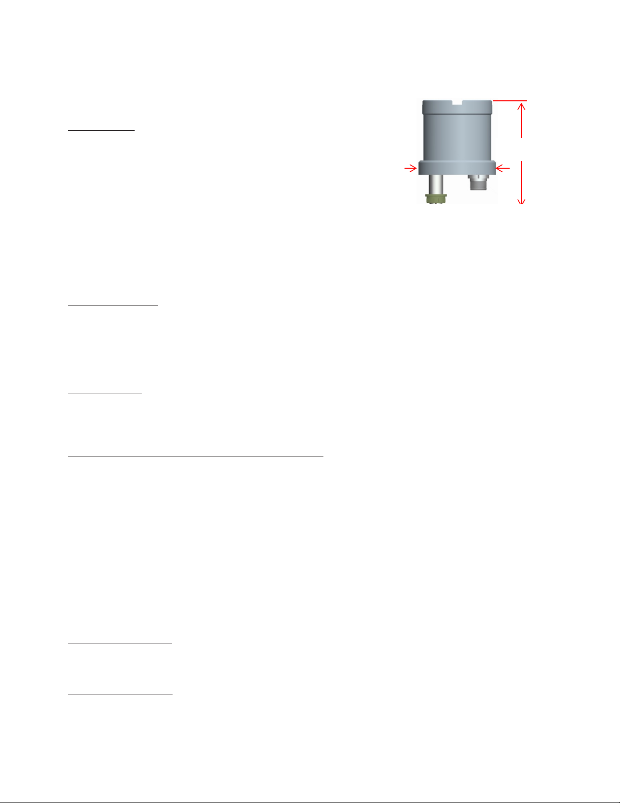
C.TechnicalSpecifications
ModelMS2600E‐HighResolutionER4‐20mATransmitter
PhysicalData
InstrumentWeight: 3.70lb.(1.68Kg)
TotalWeightw/Accessories:5.76lb.(2.61Kg)
InstrumentDimensions:6.0"Hx4.0"Dia
(15.25cmHx10.16cmDia)
OperatingTemperature:
StorageTemperature:
32°to158°F(0°to70°C)
-40°to176°F(‐40°to80°C)
EnclosureMaterial:316StainlessSteel
MountingSpecifications:Directprobemount(standard)
Maybepolemountedusingoptionalhardware
(Uptoa2.5”(6.35cm)Dia.pole)
PerformanceData
MeasurementType: ERmeasurementusinganystandardERprobetype
(WireLoop,TubeLoop,Cylindrical,Flush,Strip,etc.)
Range:0‐100%ofprobelife
Resolution:0.0015%ofProbeLife(16‐bit)
CycleTime:1Minute
ElectricalData
PowerRequirements:10to28VDC
MaximumProbeCableDistance:30ft(9.1m)
OutputSpecifications:4‐20mACurrentLoopOutput
HazardousLocationCertifications–IntrinsicSafety
USA/CanadaConformstoANSI/ULStd.60079‐0,60079‐11,61010‐1
CAN/CSAStd.E66079‐0,E60079‐11&CAN/CSAC22.2No.61010‐1
ClassI,Zone0,AExiaIICT4Ga
Zone20,AExiaIIICT130°CDa
‐20°C≤Ta≤+70°C
EuropeandWorldwideII1GExiaIICT4Ga
(ATEXandIECEx)II1DExiaIIIT130°CDa
‐20°C≤Ta≤+70°C
ATEXCertificateNo:ITS14ATEX27981X
IECExCertificateNo:IECExITS14.0010X
X.Probedielectricrating<500Vr.m.s.Donotexceed.
IncludedAccessories
33’(10meters)CurrentLoopWiringHarness(providedtofacilitatewiringtoanearbyjunctionbox,can
becuttolengthifrequired),MeterProver,OperationsManual
OptionalAccessories
ProbeExtensionCable,RemoteMountingHardware
4.0”Dia
(10.16cm)
6.0”H
(15.25cm)
Figure1.MS2600EDimensions

4
II.InstallationandOperation
A.ReceivingtheMS2600ETransmitter
ChecktheMS2600ETransmitterforanyshippingdamagewhenitisfirstreceived.WhentheMS2600E
isunpacked,verifythatthefollowingitemsareincluded:
MS2600ETransmitter
CurrentLoopWiringHarness
MeterProver
User’sManual
ProbeCable(optional,forremote‐mountonly)
MountingHardware(optional,forremote‐mountonly)
Intheeventofshippingdamage,quantityshortage,ormissingitems,itisrecommendedthatthe
eventisdocumentedimmediatelyandthatdigitalphotographsaretaken.Anyshortagesormissing
itemsshouldbereportedtoMetalSamplesimmediately.Intheeventofshippingdamage,aclaim
shouldbeopenedwiththeresponsiblecarrier.
B.Installation
CAUTION:Usingthisproductinanywayotherthanthatspecifiedwithinthismanualmayimpairthe
intrinsicsafetyprotection.
InstallationoftheMS2600ETransmitterinvolvesthefollowingsteps:
1. PhysicalMounting
2. ElectricalConnection
3. SetupandProgramming
1.PhysicalMountingandProbeConnection
WhenselectingalocationtomounttheMS2600Eitisimportanttoconsiderthesurrounding
environment.Toensureproperoperation:
DonotmounttheMS2600Einalocationthatexceedsitsoperatingtemperature.
AvoidmountingtheMS2600Enearsourcesofstrongelectricalnoise.
Ensurethatthereissufficientclearanceforinstallationandtoopenthetransmittercover
afterwards.
a.Direct‐ProbeMounting
TheMS2600Eisdesignedfordirect‐probemountingwhicheliminatestheneedforadditional
hardwareandtransmitter‐to‐probecabling.Thisgreatlysimplifiesinstallation,reducescosts,and
minimizeselectricalnoisethatcanbecoupledontoprobecablingfromnearbyelectricalequipment.
BeforemountingtheMS2600E,firstensurethattheprobeisinstalledproperlyandsecurely.During
installationitisimportantthatyoudonotapplyexcessiveforceontheprobeorseals,asdoingso
couldbreakthesealandresultinsystemleakage.
5
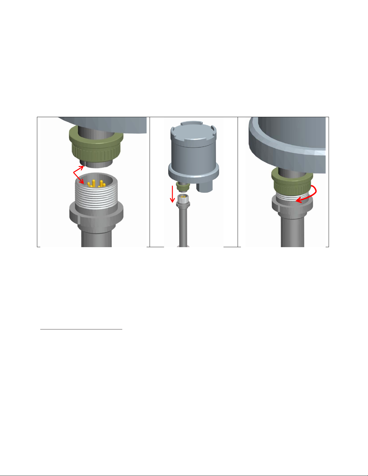
TomounttheMS2600E:
1. Alignthekeywaysofthetransmitterandprobeconnectors.
2. Insertthetransmitterconnectorplugfullyintotheprobeconnectorreceptacle.
3. Securethetransmittertothetopoftheprobebytighteningthecouplingnut.
NOTE:Hand‐tightissufficient.Donotover‐tightenthecouplingnut.
NOTE:Neverforcetheconnectorstomate.Ifthereisresistance,stopandcheckforbentpinson
theprobeandforforeignmaterialinthefemalesocketsofthetransmitterconnector.Gently
straightenanybentpinsandclearanyforeignmaterialthatmaybefound.
Figure2.MS2600EDirectMountInstallation
b.RemoteMounting
Whenitisnotpracticaltodirect‐probemounttheMS2600E,theunitcanberemotemountedinstead.
InthiscasetheinstrumentismountedtoaseparatemountingpoleusingtheoptionalRemote
MountingHardwareKit.TheMS2600EisthenconnectedtotheERprobeviatheoptionalprobe
extensioncable.Whenpossible,theMS2600Eshouldbemountedwithin10’(3m)oftheprobeto
keeptheprobecablingshortandminimizesignaldegradation.
2.CurrentLoopConnection
a.MakingConnections
TheMS2600Ecurrentloopconnectionismadeviatheexternal6‐pincircularconnectorasshown
below.Thishermeticallysealedconnectorpreventsmoistureingress,andeliminatestheneedfor
internalwiringbyanoperatorwhichreducestheriskofdamagetothecircuit.
AlignKey
Insert
Connector Tighten
CouplingNut
12 3

6
Figure3.MS2600ECurrentLoopConnector
Tofacilitatewiring,athirty‐threefoot(10meter)CurrentLoopWiringHarnessisprovided.Thiswiring
harnessconnectsdirectlytothe6‐pinconnector,andextendstoanearbyjunctionbox(notincluded)
tomakethenecessarywiringconnectionstothecurrentloopwiringfromthecontrol(DCS/SCADA)
system.Thewiringharnesscanbecuttolengthifrequired.
Figure4.MS2600EWiringHarness
NOTE:DonotconnectcableshieldingtotheTransmitter.Theshieldmustremainfloatingatthe
Transmitter.
ThemaximumpermissiblelengthofthecurrentloopwiringbetweentheMS2600ETransmitterand
thecontrolsystemisdeterminedbythecontrolsystemsupplyvoltage,theelectricalresistanceofthe
currentloopcableandtheloadofthecontrolsysteminput.IftheTransmitteristobeinstalledina
safearea,refertosectionc.WiringforaSafeAreaInstallationfordetails.IftheTransmitteristobe
installedinahazardousarea,refertosectiond.WiringforaHazardousAreaInstallation.
b.Grounding
TheMS2600Eenclosureisgroundedinternallythroughthewiringharness,butanadditional,external
groundingterminalisprovidedaswell.Theenclosureshouldbegroundedproperlyusingtheexternal
groundingterminaltoensuresafeoperation.
CurrentLoopConnector
JunctionBox
(NotIncluded)
MS2600E
Wiring Harness

7
c.WiringforaSafeAreaInstallation
CAUTION:Whenusedinnon‐hazardousareas,equipmentmustbesuppliedwithapre‐approvedpower
supplyunitorapprovedequipmentwiththefollowingmaximuminputparameters.
Ui=28V,Ii=93mAandPi=0.65W
Thepre‐approvedequipmentmustbecertifiedtotheelectricalsafetystandardsforequipmentin
ordinarylocation.ForExampleEN/IEC/CSAUL61010‐1,EN/IEC/CSAUL60950‐1etc…,
Forbasicsafeareawiringinformationrefertothecircuitdiagramshownonpage19.Usethefollowing
equationtodeterminemaximumpermissiblecablelength:
10
4∗10
Where:
D=Max.cablelengthinfeet.
VS=Powersupplyvoltage.
R=Cableresistanceinohmsper1000feet.
Example:
VS=24Volts
R=16.1(22AWGcable)
24 10
4∗10
16.1 21,739
d.WiringforaHazardousAreaInstallation
CAUTION:Thissectionprovidesgeneralguidelinesforhazardousareawiring.However,regardlessof
anythingstatedhere,theMS2600Emustbeinstalledinfullcompliancewiththecontroldrawing
locatedonpage18andallofthelocalarearequirements.
CAUTION:WhenusedinHazardousareas,equipmentmustbesuppliedwithapre‐approvedpower
supplyunitorapprovedequipmentviaacertifiedintrinsicallysafebarrieroragalvanicallyisolated
barrier)withthefollowingmaximuminputparameters.
Ui=28V,Ii=93mAandPi=0.65W
Wheneveranelectricallydrivensensorormeasuringdeviceisusedinapotentiallyexplosive
environmentthemeasuringsystemmustbeinstalledinsuchawaythatelectricalenergyiseither
effectivelyisolatedfromtheexplosiveenvironment(viaexplosive‐proofcontainers,cableconduits,
etc.)ortheamountofelectricalenergyproducedinthehazardousareamustbelimitedtoan
intrinsicallysafelevel.
LimitingelectricalenergyisthemostpracticalmethodofprotectingtheMS2600Emeasuringsystem
whentheTransmitterisinstalledinahazardousarea.IntheMS2600Esystem,electricalenergylimits
aremaintainedbytheuseofarepeatersafetybarrier(oritsequivalent)installedinthe4‐20mA
currentloopperstandardpractice.Thesafetybarriermustbelocatedinthesafeareanearthe

8
boundarybetweenthesafeandhazardousareas.Thesafetybarrierwillrepeatthesignalcurrent
generatedbytheTransmitterandwillrelaythesignaltothedatareceivingstation.
Caution:WhenasafetybarrierisusedwiththeMS2600Esystem,thecurrentloopcablemustbe
connectedtothebarrier’shazardousareaterminals.Allotherconnectionsmustbemadetothe
barrier’ssafeareaterminals.
ThetypeofrepeatersafetybarrieremployedintheMS2600Esystemdependsonthespecific
classificationofthehazardousenvironmentinquestion.MetalSampleswillprovide,uponrequest,
assistanceandtechnicaladviceintheselectionofarepeatersafetybarrieroritsequivalent.
Formostinstallations,MetalSamplesrecommendstheintrinsicallysafeMTL5441RepeaterPower
Supply.
ThemaximumlengthofthecurrentloopcablethatconnectstheMS2600ETransmittertothe
repeatersafetybarrierisasfollows:
Example:
17.5Volts
22AWGCable=5,434feetmaximum
16AWGCable=21,788feetmaximum
CAUTION:Forhazardousareainstallations,themaximuminductanceandcapacitanceoftheloop
wiringbetweenthesafetybarrierandthetransmittercannotexceedtheentityparametersofthe
selectedbarrier.

9
3.SetupandOperation
a.ProbeSelectionSwitches
HousedwithintheMS2600Eenclosureareprobeselectionswitcheswhichallowtheinstrumenttobe
setforanystandardERprobetype.Theyalsoallowtheinstrumenttobeplacedintoseveraltest
modeswhichoutputfixedvalues,allowingverificationofthecurrentloopconnectionandDCS
program.
Figure5.ConnectorandSwitchDetails
Setting
Switch
1
Switch
2
Switch
3
Switch
4
Operating
Positions
Wire Loop Off (↓)On (↑) On (↑) Off (↓)
Tube Loop/Flush On (↑) Off (↓)On (↑) Off (↓)
Cylindrical*Off (↓)Off (↓)On (↑) Off (↓)
Test
Positions
4mA Output On (↑) On (↑) Off (↓)Off (↓)
20mA Output Off (↓)On (↑) Off (↓)Off (↓)
4-20mA Sweep On (↑) Off (↓)Off (↓)Off (↓)
Table2.ProbeSwitchSettings
*Cylindricalprobesettingisillustrated.
ProbeSelectionSwitch
(Seedetailbelow)
4‐20mACurrent
L
oop
Co
nn
ec
t
o
r
ProbeCableConnector

10
b.TestingtheCurrentLoop
i.Calibration
TheMS2600Eisfullycalibratedwhenshippedfromthefactory.Thecalibrationsettingsarefixedto
avoidaccidentalchangewhichcouldresultinerroneousdata.Nofieldcalibrationisrequired.
However,itisimportanttotesttheMS2600Euponinstallation,andduringperiodicmaintenance
inspections,toensuretheunitisoperatingproperly.
ii.Testingloopoutputzero(4mA)andspan(20mA)
TheMS2600EProbeSelectionSwitches(page9)offerthreetestsettingsthatallowtheunittobe
placedintovariousdiagnosticmodesasfollows:
1) 4mAOutput–Forcesaconstant4mAoutputonthecurrentloop.
2) 20mAOutput–Forcesaconstant20mAoutputonthecurrentloop.
3) 4‐20mASweep–Causestheoutputtocontinuallycyclefrom4mAupto20mA.
Thesetestmodescanbeusefulwhentroubleshootingproblemswiththecurrentloopwiringand
DCS/SCADAsystem.
iii.TestingtheMS2600EwiththeMeterProver
AMeterProverisprovidedtoallowroutinechecksoftheMS2600E.TheMeterProversimulatesa
WireLooptypeprobeatafixedvalue.TotesttheMS2600EwiththeMeterProver:
1) Disconnectpower.
2) DisconnecttheMS2600Efromtheprobe(oriftheMS2600Eisremote‐mounted,disconnect
theprobeextensioncablefromtheprobe.)
3) ConnecttheMeterProvertotheMS2600Eprobeconnectorstem(ortotheprobeextension
cableiftheMS2600Eisremote‐mounted.)
4) LoosentheMS2600EEnclosureLockScrew.
5) UnthreadandremovetheMS2600Ecover.
6) ChangetheProbeSelectionSwitchestotheWireLoopposition(seepage9.)
7) Reconnectpowerandallowtheinstrumenttomeasureforseveralminutestostabilize.
8) Afterseveralminutesobservethetransmitteroutput.Theoutputshouldcloselymatchthe
valueprintedontheMeterProverlabel.
IfthetransmitteroutputmatchestheMeterProvervalue,youmayreturntheProbeSelection
SwitchestotheirprevioussettingandreconnecttheMS2600Etotheprobe.Ifthetransmitteroutput
showsasignificantdifferencecomparedtotheMeterProvervalue,furthertroubleshootingmaybe
required.Refertopage14fortroubleshootingorcontactthefactoryforfurtherassistance.
BesuretoreinstalltheenclosurecoverandtightentheLockScrewwhenputtingtheMS2600Eback
intoservice.

11
c.InterpretingData
i.MetalLoss
TheMS2600EmeasurestheMetalLossofanERprobeandconvertsthatvaluetoalinearized4‐20mA
currentloopoutput.The4‐20mAoutputisdirectlyproportionaltothecumulativeMetalLossofthe
ERprobeatanygiventime.Theoverallspanofthe4‐20mAoutputisproportionaltothelifeofthe
probeinuse,soforDCS/SCADAprogrammingthe4‐20mAsignalcanbescaledasfollows:
4mA=0mils(0%MetalLoss)
20mA=ProbeLifeinmils(100%MetalLoss)
TheProbeLifecanbefoundinTable1andisalsolistedontheMetalSamplesprobetag(asthe
“Multiplier”.)
Figure6.MetalSamplesProbeTag
Figure7illustratestherelationshipbetweenLoopCurrentandMetalLoss.Inthisexampleaprobe
witha10‐millifeisassumed.However,theXaxiscouldbechangedtorepresentanyProbeLife.
Figure7.OutputRelationship
Asseenhere,thetransmitteroutputbeginsat4mAforanewprobe(zeroMetalLoss)andincreasesas
theprobeelementcorrodes,eventuallyreachingamaximumof20mAwhentheprobesensing
elementhasbeencompletelyconsumedbycorrosion(inthiscase,10milsofMetalLoss.)Atthistime
theprobehasreacheditsend‐of‐lifeandmustbereplaced.
ii.CalculatingCorrosionRate
Asexplainedpreviously,ERprobesandinstrumentsreportMetalLoss.However,thevaluethatisof

12
ultimateinterestisCorrosionRate.TheCorrosionRateisessentiallyMetalLossovertime,sothe
CorrosionRatecanbecalculatedusingthefollowingformula:
CorrosionRatempy ∆LoopCurrentmA
16 365
∆Timedays ProbeLifemils
where:
LoopCurrent(mA)isthedifferencebetweentworeadings
Time(days)isthetimedifferencebetweenthosetworeadings
Itisacommonpracticetoprogramthisformulaintothecontrol(DCS/SCADA)systemandhaveit
calculateCorrosionRateonacontinualbasisfromtheMetalLossdata.Thechallengeindoingthisis
selectinganappropriatetimeinterval.Usinganintervalthatistooshortmaygiveerraticresults,
whileselectinganintervalthatistoolongmaygiveresultsthatareinsensitivetosystemupsets.The
idealtimeperioddependsonmanyfactors,andwillvaryfromsystemtosystem.Itmaytakesome
trialanderrortosettleonthebesttimeperiodforyourinstallation.
InsomecasesitmaybenecessarytoreviewtherawMetalLossdataandmanuallyapplythe
CorrosionRateformulatoperiodsofinterest.Forexample,lookatthegraphbelowandseehow
muchthecalculatedCorrosionRatecanvarydependingonthetimeperiodused.
Figure8.CorrosionRatescalculatedfromMetalLossdata
Whileeachoftheresultsisvalidfortheselectedtimeperiod,theoneofmostinterestisthevalueof
11.81mpywhichrepresentssometypeofsystemupset.WhentheCorrosionRateiscalculated
automaticallyonapre‐selectedtimeperiod,thereisnoguaranteethattheselectedtimeperiodwill
alwayscoincidewithsystemupsetssuchasthis.Thatiswhymanualreviewandinterpretationof
MetalLossdataisalsohelpful.

13
d.Commissioning
OncetheMS2600Ehasbeeninstalled,tested,andproperlyconfiguredfortheprobeinuse,itcanthenbe
closedandputintoservice.First,performonelastvisualinspectiontoensurethatallelectrical
connectionsaresecure,andthattheenclosureo‐ringisinplaceandisingoodcondition.Thenthreadthe
enclosurelidontothebasefully.Oncethelidhasbeenthreadedintoplace,tightentheLockScrewto
preventunauthorizedtampering.
Figure9.EnclosureLockScrew
CAUTION:TheLockScrewontheinstrumentbasemustbetightenedsecurelytopreventunauthorized
personnelfromopeningtheMS2600E,andensurethattheintrinsicsafetyisnotviolated.Onlyqualified
personnelshouldbeallowedtoinstall,operate,andmaintenancetheMS2600E.
C.Maintenance
Onceinstalled,theMS2600Erequireslittlemaintenance.However,itisimportanttoverifythefollowingitems
periodicallytoensurecontinuedsafeoperation.
CAUTION:BeforeperforminganytestsormaintenanceontheMS2600E,ensurethatallhazardousarea
requirementsaremet.
InspectionItemFrequency
Inspecttheenclosureo‐ringforanysignsofdamage.Replaceasnecessary.Annually
Inspecttheprobeconnectoro‐ringforanysignsofdamage.Replaceasnecessary.Annually
Inspecttheexternalelectricalconnectionsforsignsofcorrosion,mechanicaldamage,or
foreignmatterthatcouldcausedamageorcauseanelectricalshort.Cleanasnecessary.
Annually
EnsurethatthelockingscrewisinplaceandissecureAnnually
TheMS2600Eenclosureismadeofcorrosion‐resistant316stainlesssteel.However,it
shouldstillbecheckedperiodicallyforanysignsofcorrosion.
Annually
Checkforanysignsofmoistureingresswithintheenclosure.Annually
ContactMetalSamplesforreplacementpartsorifinstrumentrepairisnecessary.

14
D.Troubleshooting
IftheMS2600Edoesnotseemtoperformasexpected,checkthefollowingitems:
CAUTION:BeforeperforminganytestsormaintenanceontheMS2600E,ensurethatallhazardousarea
requirementsaremet.
1. Ensurethattheprobeisoperationalandisnotcompletelycorroded.Thiscanbedoneintwoways.
a. TesttheprobewithaportableERmeterifavailable.
b. Testtheprobewithaportableresistanceorcontinuitymeterasfollows:
i. Connectonetestleadtopin‘A’oftheprobes6‐pinconnector.
ii. Measurecontinuitytoeachoftheotherpins.Thereshouldbecontinuity(low
resistance)toeachpin.
NOTE:Continuityoneachpindoesnotensurethattheprobeisgood.However,ifyou
findanopencircuitonanypinsthenitisalmostcertainthattheprobeisbadandshould
bereplaced.
2. EnsurethattheProbeSelectionSwitchesaresetcorrectlyfortheprobebeingused.Confirmthe
probetype,andrefertoTable2onpage9toverifytheappropriateswitchsettings.
3. Performavisualinspectionofthecircuitboardstolookforanysignsofmechanicalorelectrical
damage.
4. Ensurethatallelectricalcablesandwiringareingoodcondition.
5. Ensurethatallelectricalcontactsaresecureandfreeofcorrosion.
6. Ensurethatthereisadequatesupplyvoltageatthe4‐20mACurrentLoopConnector.
7. Verifythatthesupplyvoltagepolarityiscorrect.
8. Ifthereisinsufficientsupplyvoltageonthe4‐20mACurrentLoopConnector,checkthesafety
barrier(ifapplicable)forablownfuseoranyotherfailure.
9. TesttheMS2600EusingthesuppliedMeterProver(seepage10.)
10. TesttheMS2600Ewithalocalmulti‐meterorloopcalibrator.
Thesebasicchecksshouldindicatethesourceofanyproblem(probe,powersupply,wiring,etc…)Ifitis
determinedthattheMS2600Eismalfunctioning,orifyouneedfurtherassistanceintroubleshooting,
contactMetalSamplesTechnicalSupport.
CAUTION:IftheMS2600Eshowsanysignsofdamageremoveitfromserviceimmediatelyandconsultthe
factory.

15
III.ServiceandWarrantyInformation
A.Warranty
MetalSampleswarrantsthatanypartoftheMS2600Eandaccessorieswhichprovestobedefectivein
materialorworkmanshipwithinoneyearofthedateoforiginalshipmenttoPurchaserwillberepairedor
replaced,atMetalSamplesoption,freeofcharge.Thiswarrantydoesnotcover(1)probeassemblies,(2)
itemsexpendableinnature,or(3)itemssubjecttodamagefromnormalwear,misuseorabuse,orfailure
tofollowuseandcareinstructions.
AlldamageditemsaretobeshippedatPurchaser’sexpensetoandfromMetalSampleswhichshallhave
therighttofinaldeterminationastotheexistenceandcauseofadefect.
TheforegoingshallconstitutethesoleandexclusiveremedyofanypurchaserofMetalSamplesproducts
forbreachofwarrantyandISEXCLUSIVEANDINLIEUOFALLOTHERWARRANTIES,EXPRESSED,IMPLIED
ORSTATUTORY,INCLUDINGTHEIMPLIEDWARRANTIESORMERCHANTABILITYANDFITNESS.INNOEVENT
SHALLMETALSAMPLESBELIABLEFORSPECIALORCONSEQUENTIALDAMAGES,ORFORANYDELAYIN
THEPERFORMANCEOFTHISWARRANTYDUETOCAUSESBEYONDITSCONTROL.
Thetechnicalinformationandsuggestionscontainedhereinarebelievedtobereliable,buttheyarenotto
beconstruedaswarrantiessinceconditionsofusearebeyondourcontrol.
B.ObtainingServiceandReturningtheInstrumentforRepair
Ifyouexperienceproblemswithyourinstrumentpleasecontactthefactoryat256‐358‐4202andaskfor
customersupportforinstrumentation.Ourcustomersupportdepartmentwillassistyouin
troubleshootingyourinstrument.
Mostissuescanberesolvedoverthephone,butinsomecasesitmaybenecessarytoreturnyour
instrumentforfurtherevaluationandrepair.Inthiscase,pleaseobtainaReturnMaterialsAuthorization
(RMA)numberfromthesalespersonorsupporttechnician.ThisRMAnumberwillensurethatyour
instrumentisroutedtothecorrectdepartmentwhenitisreceivedatthefactory.
AfterreceiptofanRMAnumberyoumaypackyourinstrumentforreturn.Besuretopackyour
instrumentinasturdyboxandtopaditsufficientlytoavoiddamageduringtransit.Alsobesureto
completethe“InstrumentRepairForm”onthenextpageandincludeacopywithyourrepair.Thiswill
ensurethattherepairdepartmenthassufficientinformationregardingtheproblemsyouareexperiencing
withyourinstrument,aswellasthebilling,contact,andreturnshippingdetailsfortherepair.
OnceyouhaveobtainedanRMAnumber,completedthe“InstrumentRepairForm”,andpackedyour
instrumentsecurely,pleaseshipitprepaidtothefollowingaddress:
MetalSamples
152MetalSamplesRoad
Munford,AL36268
ATTN:RMA#_____
NOTE:BesuretolistyourRMAnumberintheattentionline(shownasblanksintheexampleabove.)
16
C.InstrumentRepairForm
ThisformmaybephotocopiedforusewhenreturninganinstrumenttoMetalSamplesforrepair.
Pleasefillinallknowninformationandencloseacopyofthecompletedformwiththeinstrument.
GeneralInformation
Model
Number
Serial
Number
RMA
Number
Dateo
f
Purchase*
*Ifknown.
ContactInformationforRepair
Contact
Name
Company
Phone
Number
E‐mail
Address
ReturnShippingInformation
Recipient
Name*
Company*
Return
Address
*Ifdifferentthanabove.
ReasonforReturn.(Provideasmuchdetailaspossible.Attachadditionalpagesifrequired.)
InvoiceInstructions(Fornon‐warrantyrepairs)
Invoicemefortherepair
(RequiresanopenaccountwithMetalsamples.)
Reference
PO#
Contactmeforcreditcardinformation
(Forsecuritypurposes,donotlistcreditcardinformationonthisform..)
Table of contents
Other Metal Samples Transmitter manuals

Metal Samples
Metal Samples MS2700E User manual

Metal Samples
Metal Samples CORR Velox MS2800E User manual

Metal Samples
Metal Samples MS2601E User manual

Metal Samples
Metal Samples CORR VELOX MS2801E User manual

Metal Samples
Metal Samples MS2701E User manual

Metal Samples
Metal Samples MS2901E User manual

Metal Samples
Metal Samples MS2500E User manual

Metal Samples
Metal Samples MS2500L User manual
 user manual")


