Metal Samples MS2700E User manual

MS2700E
High Resolution ER RS-485 Transmitter
Operator’s
Manual
Metal Samples Company
ADivision of Alabama Specialty Products, Inc.
152 Metal Samples Rd., Munford, AL 36268 Phone: (256) 358-4202 Fax: (256) 358-4515


Table of
Contents
I.Introduction..............................................................................................................................................1
A.GeneralDescription...................................................................................................................1
B.PrinciplesofOperation..............................................................................................................1
C.TechnicalSpecifications.............................................................................................................3
II.InstallationandOperation.......................................................................................................................4
A.ReceivingtheMS2700Etransmitter..........................................................................................4
B.Installation.................................................................................................................................4
1.PhysicalMountingandProbeConnection...................................................................4
a.Direct‐ProbeMounting
......................................................................................4
b.RemoteMounting..............................................................................................5
2.PowerandDataConnections.......................................................................................5
a.MakingConnections........................................................................................5
b.Grounding.........................................................................................................6
c.SafeAreaInstallation........................................................................................7
d.HazardousAreaInstallation...............................................................................7
3.SetupandOperation.......................................................................................................9
a.ProbeSettings.................................................................................................9
b.RS‐485CommunicationSettings...................................................................10
i.BaudRateandDefaultCommunicationParameters.............................11
ii.DeviceAddress......................................................................................11
iii.CommunicationProtocols.....................................................................11
iv.TerminationResistor.............................................................................11
v.DataRegisters.......................................................................................11
c.CalibrationandTesting.................................................................................12
i.Calibration...............................................................................................12
ii.Testingoutputzeroandspan.................................................................12
iii.TestingtheMS2700EtransmitterwiththeMeterProver.......................12
d.InterpretingData...........................................................................................13
i.MetalLoss................................................................................................13
ii.CalculatingCorrosionRate.......................................................................14
e.Commissioning..............................................................................................15
C.Maintenance............................................................................................................................15
D.Troubleshooting.......................................................................................................................16
III.ServiceandWarrantyInformation.......................................................................................................17
A.Warranty...................................................................................................................................17
B.ObtainingServiceandReturningtheInstrumentforRepair....................................................17
C.InstrumentRepairForm...........................................................................................................18
AppendixA‐Drawings...............................................................................................................................19
ControlDrawing(HazardousAreaWiringDiagram).....................................................................20
SafeAreaWiringDiagram.............................................................................................................21
AppendixB–RevisionHistory...................................................................................................................22


1
I.Introduction
A.GeneralDescription
ThemodelMS2700E transmitterisahighresolutioninstrumentdesignedtomeasureandtransmit
corrosion(metalloss)datafromanElectricalResistance(ER)probetoaplantcontrolsystemorother
recordingdevice.TheMS2700E transmitterutilizesRS‐485communicationwhichallowsmultiple
unitstobedaisy‐chained,simplifyinginstallationandreducingassociatedcosts.TheuseoftheRS‐485
protocolalsoallowsthetransmittertobeplacedgreatdistancesfromthecontrolsystemorrecorder
whilemaintaininggoodnoiserejection.Practicaldistancescanbeupto4000feet.Additionally,the
MS2700E transmitteroffersuser‐selectableRTUorASCIIcommunicationprotocolsmakingithighly
versatile.
TheMS2700E transmitteriscompatiblewithalltypesofMetalSamplesERprobes,aswellasany
standardERprobefromothermanufacturers.Unlikecompetitors’products,theMS2700E
transmitterdoesnotrequirefactorymodificationtoaccommodatedifferentprobetypes.Theprobe
typecanbeeasilychangedatanytimeusingtheon‐boardprobeselectionswitches(seepage9.)
TheMS2700E transmitterisavailableasdirect‐mount(standard)orremote‐mount.Thedirect‐mount
versionismounteddirectlytotheERprobe.Thisoptionoffersthesimplestinstallationandminimizes
noiseproblems.Theremote‐mountoptionallowstheMS2700E transmittertobemounted
independentlyfrom(butincloseproximityto)theERprobe.Itisthenconnectedtotheprobeviaa
shortprobecable.(Seepages5and6formountingdiagramsandspecifications.)
B.PrinciplesofOperation
TheMS2700E transmitteroperatesontheElectricalResistance(ER)techniqueandisusedin
conjunctionwithanERprobe.TheERprobeutilizesaresistivesensingelementmanufacturedfrom
thematerialofinterest(oracloseapproximation)whichisexposedtoacorrodingenvironment.This
iscalledtheExposedorCorrodingElement.TheresistanceoftheExposedElementisdirectlyrelated
toitsthickness,soastheelementcorrodestheresultinglossofmetalcausesaproportionalincrease
intheelement’sresistance.TheprobealsocontainsaninternalReferenceElementwhichisusedto
compensatefortheinfluencesoftemperatureontheExposedElement.
TheMS2700E transmitterisdesignedtoworkwithanystandardERprobe,butitisrecommendedthat
CylindricalandLargeFlushtypeprobesbeusedtoensureoptimumperformance.Theirphysical
designplacestheReferenceElementincloserproximitytotheExposedElementcomparedtoother
probetypes,providingmoreeffectivetemperaturecompensationandthusreducingtheeffectsof
thermalnoise.
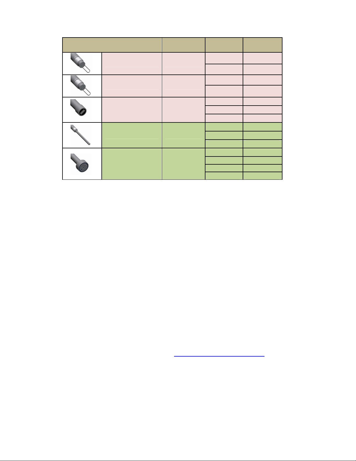
Becausetheyaredesignedtocorrode,ERprobesaresacrificialinnature.EachERprobewillhavea
finitelifethatisbasedontheelementthickness.ERprobesareavailableinanumberofgeometries
andthicknessesdesignedtosuitawidevarietyofapplications.Table1liststhecommonERelement
optionsavailablefromMetalSamplesandtheeffectivelifeofeach.
2
ElementTypeCompatibilityThicknessProbeLife
(Span)
TubularLoopCompatible
42
84
WireLoopCompatible
4010
8020
Flush(Small)Compatible
4 2
8 4
20 10
CylindricalPreferred
10 5
20 10
50 25
Flush(Large)Preferred
52.5
10 5
20 10
40 20
Table1.StandardERProbeElements
TheMS2700E transmittermeasuresanERprobeutilizingahigh‐resolution,16‐bitmeasurement.
Thisallowstheunittodetectmuchsmalleramountsofmetalloss,thusrespondingfasterto
corrosioneventsandupsets.At16‐bitresolutiontheMS2700E transmittercanmeasuremetalloss
amountsassmallas0.0015%oftheprobelife.
MetallossreadingstakenbytheMS2700E transmitterareoutputasadigitalRS‐485signalwhich
canbefedintoaplantcontrolsystemorotherrecordingdevices.TheMetalLossisrepresentedby
a16‐bitdigitalvaluebetween0and65535,where:
0=0mils(0%MetalLoss)
65535=ProbeLife*inmils(or100%MetalLoss)
*TheProbeLife(orSpan)oftheprobebeingused(seetable1above.)
TheMetalLossdatacanbeusedtocalculatethecorrosionratebetweenanyperiodsofinterest.
Thisiscoveredinmoredetailonpages13and14.MoreinformationonERprobes,theirtheory,
selection,andusecanbefoundonourwebsiteat http://www.alspi.com/erintro.htm.

3
C.TechnicalSpecifications
ModelMS2700EHighResolutionERRS‐485ModbusTransmitter
PhysicalData
InstrumentWeight: 3.70lb.(1.68Kg)
TotalWeightw/Accessories:5.76lb.(2.61Kg)
InstrumentDimensions:6.0"Hx4.0"Dia
(15.25cmHx10.16cmDia)
OperatingTemperature: ‐4°to158°F(‐20°to70°C)
StorageTemperature: ‐40°to176°F(‐40°to80°C)
EnvironmentalRating: IP66
EnclosureMaterial:316StainlessSteel
MountingSpecifications:Directprobemount(standard)
Maybepolemountedusingoptionalhardware
(Uptoa2.5”(6.35cm)Dia.pole)
PerformanceData
MeasurementType: ERmeasurementusinganystandardERprobetype
(WireLoop,TubeLoop,Cylindrical,Flush,Strip,etc.)
Range:0‐100%ofprobelife
Resolution:0.0015%ofProbeLife(16‐bit)
CycleTime:75Seconds
ElectricalData
PowerRequirements:10to28VDC
MaximumProbeCableDistance:30ft(9.1m)
OutputSpecifications:RS‐485Modbus,RTUorASCIIProtocol(SwitchSelectable)
2400/4800/9600/19.2KSelectableBaud
32MaximumUnits(Addresses1to32)
HazardousLocationCertifications–IntrinsicSafety
USA/CanadaConformstoANSI/ULStd.60079‐0,60079‐11,61010‐1
CAN/CSAStd.E66079‐0,E60079‐11&CAN/CSAC22.2No.61010‐1
ForStand‐AloneUseForMulti‐DropUse
ClassI,Zone0,AExiaIICT4GaClassI,Zone0,AExiaIIBT4Ga
Zone20,AExiaIIICT130°CDaZone20,AExiaIIIBT130°CDa
‐20°C≤Ta≤+70°C‐20°C≤Ta≤+70°C
EuropeandWorldwideForStand‐AloneUseForMulti‐DropUse
(ATEXandIECEx)II1GExiaIICT4GaII1GExiaIIBT4Ga
II1DExiaIIICT130°CDaII1DExiaIIIBT130°CDa
‐20°C≤Ta≤+70°C ‐20°C≤Ta≤+70°C
ATEXCertificateNo:ITS14ATEX28092X
IECExCertificateNo:IECExITS14.0052X
X‐seeSpecialConditions(page7)
IncludedAccessories
33’(10M)WiringHarness,MeterProver,OperationsManual
OptionalAccessories
ProbeExtensionCable,RemoteMountingHardware
4.0”Dia
(10.16cm)
6.0”H
(15.25cm)
Figure1.OverallDimensions

4
II.InstallationandOperation
A.ReceivingtheMS2700ETransmitter
ChecktheMS2700E Transmitterforanyshippingdamagewhenitisfirstreceived.Whentheunitis
unpacked,verifythatthefollowingitemsareincluded:
Transmitter
WiringHarness
MeterProver
User’sManual
ProbeCable(optional,forremote‐mountonly)
MountingHardware(optional,forremote‐mountonly)
Intheeventofshippingdamage,quantityshortage,ormissingitems,itisrecommendedthatthe
eventisdocumentedimmediatelyandthatdigitalphotographsaretaken.Anyshortagesormissing
itemsshouldbereportedtoMetalSamplesimmediately.Intheeventofshippingdamage,aclaim
shouldbeopenedwiththeresponsiblecarrier.
B.Installation
CAUTION:Usingthisproductinanywayotherthanthatspecifiedwithinthismanualmayimpairthe
intrinsicsafetyprotection.
InstallationoftheMS2700E transmitterinvolvesthefollowingsteps:
1. PhysicalMounting
2. ElectricalConnection
3. SetupandProgramming
1.PhysicalMountingandProbeConnection
WhenselectingalocationtomounttheMS2700E transmitteritisimportanttoconsiderthe
surroundingenvironment.Toensureproperoperation:
Donotmountthetransmitterinalocationthatexceedsitsoperatingtemperature.
Avoidmountingthetransmitternearsourcesofstrongelectricalnoise.
Ensurethatthereissufficientclearanceforinstallationandtoopenthetransmittercover
afterwards.
a.Direct‐ProbeMounting
TheMS2700E transmitterisdesignedfordirect‐probemountingwhicheliminatestheneedfor
additionalhardwareandtransmitter‐to‐probecabling.Thisgreatlysimplifiesinstallation,reduces
costs,andminimizeselectricalnoisethatcanbecoupledontoprobecablingfromnearbyelectrical
equipment.
BeforemountingtheMS2700E transmitter,firstensurethattheprobeisinstalledproperlyand
securely.Duringinstallationitisimportantthatyoudonotapplyexcessiveforceontheprobeor
seals,asdoingsocouldbreakthesealandresultinsystemleakage.

5
TomounttheMS2700E transmitter:
1. Alignthekeywaysofthetransmitterandprobeconnectors.
2. Insertthetransmitterconnectorplugfullyintotheprobeconnectorreceptacle.
3. Securethetransmittertothetopoftheprobebytighteningthecouplingnut.
NOTE:Hand‐tightissufficient.Donotover‐tightenthecouplingnut.
NOTE:Neverforcetheconnectorstomate.Ifthereisresistance,stopandcheckforbentpinson
theprobeandforforeignmaterialinthefemalesocketsofthetransmitterconnector.Gently
straightenanybentpinsandclearanyforeignmaterialthatmaybefound.
Figure2.DirectMountInstallation
b.RemoteMounting
Whenitisnotpracticaltodirect‐probemounttheMS2700E transmitter,theunitcanberemote
mountedinstead.Inthiscasetheinstrumentismountedtoaseparatemountingpoleusingthe
optionalRemoteMountingHardwareKit.ThetransmitteristhenconnectedtotheERprobeviathe
optionalprobeextensioncable.Whenpossible,thetransmittershouldbemountedwithin10’(3m)of
theprobetokeeptheprobecablingshortandminimizesignaldegradation.
2.PowerandDataConnections
a.MakingConnections
TheRS‐485connectionsaremadeviatheexternal6‐pincircularconnectorCN1asshowninFigure3.
Thishermeticallysealedconnectorpreventsmoistureingressandeliminatestheneedforinternal
wiringbyanoperator,thusreducingtheriskofphysicaldamagetothecircuitboard.
AlignKey
Insert
Connector Tighten
CouplingNut
12 3

6
Figure3.RS‐485Connector
Tofacilitatewiring,athreefoot(1meter)wiringharnessisprovided.Thiswiringharnessconnects
directlytothe6‐pinconnector,andextendstoanearbyjunctionbox(notincluded)tomakethe
necessarypoweranddatawiringconnectionsfromthecontrol(DCS/PLC)system.
Figure4.MS2700ETransmitterWiringHarness
NOTE:DonotconnectcableshieldingtotheTransmitter.Theshieldmustremainfloatingatthe
Transmitter.
ThemaximumpermissiblelengthofthefieldwiringbetweentheMS2700E transmitterandthe
controlsystemisdeterminedbythecontrolsystemsupplyvoltage,theelectricalresistanceofthe
cableandtheloadofthecontrolsysteminput.IftheTransmitteristobeinstalledinasafearea,refer
tosectionc.SafeAreaInstallationfordetails.IftheTransmitteristobeinstalledinahazardousarea,
refertosectiond.HazardousAreaInstallation.
b.Grounding
TheMS2700E transmitterenclosureisgroundedinternallythroughthewiringharness,butan
additional,externalgroundingterminalisprovidedaswell.Theenclosureshouldbegrounded
properlyusingtheexternalgroundingterminaltoensuresafeoperation.
ConnectorCN1
(PowerandData)
JunctionBox
(NotIncluded)
Wiring Harness

7
c.SafeAreaInstallation
TheMS2700E transmitterisapprovedforuseinhazardousareas,butcanbeusedinnon‐hazardous
areasaswell.Forbasicsafeareawiringinformationrefertothecircuitdiagramshownonpage21.
CAUTION:Whenusedinnon‐hazardousareas,equipmentmustbesuppliedwithapre‐approvedpower
supplyunitorapprovedequipmentwhichmeetstheentityparametersshownbelow.
Thepre‐approvedequipmentmustbecertifiedtotheelectricalsafetystandardsforequipmentin
ordinarylocations(forexample,EN/IEC/CSAUL61010‐1orEN/IEC/CSAUL60950‐1).Failuretomeet
theserequirementswillvoidtheintrinsicsafetycertificationoftheequipmentandprohibititsfuture
useinhazardousareas.
d.HazardousAreaInstallation
CAUTION:Thissectionprovidesgeneralguidelinesforhazardousareawiring.However,regardlessof
anythingstatedhere,theMS2700E transmittermustbeinstalledinfullcompliancewiththecontrol
drawinglocatedonpage20andallofthelocalarearequirements.
CAUTION:WhenusedinHazardousareas,equipmentmustbesuppliedwithapre‐approvedpower
supplyunitorapprovedequipmentviaacertifiedintrinsicallysafebarrieroragalvanicallyisolated
barrier)withthefollowingentityparameters.
Input supply terminal, RS-485 channel
and connector CN2 (Combined) Connector CN1 pins A & B (J2 on PCB):
Ci = 68uF Ui = 23 Vdc
Li = 0 Ii = 88.2 mA
Co = 32uF Pi = 0.52 W
Lo = 0.14 mH Ci = 0
Li = 0
RS-485 channel at each line
Connector CN1 pins D & E (J9 on PCB):
Ui = 3.7 Vdc
Ii = 225 mA
Pi = 0.206 W
Uo =5V
Io =51mA
Po = 0.064W
Probe connector CN2 (J1 on PCB):
Uo = 5 V
Io = 503 mA
Po = 0.7 W
SpecialConditions
1.Probedielectricrating<500Vr.m.s.Donotexceed.
2.Probecannotbeinstalledintheexplosiondustatmosphere(GroupIII).
3.Networked(“daisy‐chained”)arrangementnotforuseinGroupIIC/IIICenvironment.
4.Maximum32transmittersareallowedinthedaisy‐chainarrangement.

8
Wheneveranelectricallydrivensensorormeasuringdeviceisusedinapotentiallyexplosive
environmentthemeasuringsystemmustbeinstalledinsuchawaythatelectricalenergyiseither
effectivelyisolatedfromtheexplosiveenvironment(viaexplosive‐proofcontainers,cableconduits,
etc.)ortheamountofelectricalenergyproducedinthehazardousareamustbelimitedtoan
intrinsicallysafelevel.
LimitingelectricalenergyisthemostpracticalmethodofprotectingtheMS2700E transmitterwhenit
isinstalledinahazardousarea.IntheMS2700E transmitter,electricalenergylimitsaremaintainedby
theuseofappropriatesafetybarriersinstalledinthepoweranddatawiring.Thesafetybarriersmust
belocatedinthesafeareaneartheboundarybetweenthesafeandhazardousareas.Thesafety
barrierwillrepeatthesignalcurrentgeneratedbytheTransmitterandwillrelaythesignaltothedata
receivingstation.
Caution:WhenasafetybarrierisusedwiththeMS2700E transmitter,thetransmitterwiring
connectionsmustbeconnectedtothesafetybarrier’shazardousareaterminals.Allotherconnections
mustbemadetothebarrier’ssafeareaterminals.
ThetypeofrepeatersafetybarriersusedwiththeMS2700E transmitterdependsonthespecific
classificationofthehazardousenvironmentinquestion.However,theentityparametersmustmatch
thoseoftheMS2700E transmitter.
CAUTION:Forhazardousareainstallations,themaximuminductanceandcapacitanceofthefield
wiringbetweenthesafetybarrierandthetransmittercannotexceedtheentityparametersofthe
selectedbarrier.

9
3.SetupandOperation
a.ProbeSettings
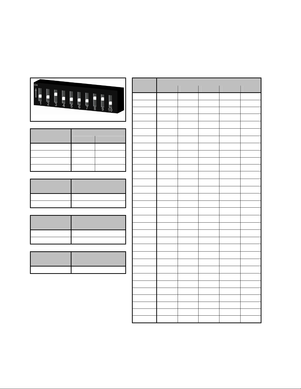
Theprobeselectionswitchesarelocatedonthetopleftcornerofthemainboardasillustratedin
Figure5below.TheseswitchesareusedtosettheERprobetype.Theyalsoallowtheinstrumentto
beplacedintoseveraltestmodeswhichoutputfixedvalues,allowingverificationoftheoutputsignal.
Table2givestheswitchsettingsforeachprobetypeandthevarioustestmodes.
Figure5.ConnectorandSwitchDetails
Switch1
Setting
Position
1 2 3 4
Operating
Positions
Wire Loop Off (↓)On (↑) On (↑) Off (↓)
Tube Loop/Flush On (↑) Off (↓)On (↑) Off (↓)
Cylindrical*Off (↓)Off (↓)On (↑) Off (↓)
Test
Positions
Zero Output (0) On (↑) On (↑) Off (↓)Off (↓)
Maximum Output
(65535) Off (↓)On (↑) Off (↓)Off (↓)
Full Scale Sweep On (↑) Off (↓)Off (↓)Off (↓)
Table2.ProbeSwitchSettings
*Cylindricalprobesettingisillustrated.
Switch1‐Probe
SelectionSwitch
(SeeTable2below)
PowerConnector
(J2)
ProbeCableConnector
DataConnector
(J9)
Switch2‐ RS‐485
ConfigurationSwitches
(SeeTable3below)
10
b. RS‐485CommunicationSettings
TheRS‐485configurationswitchesarelocatedonthetoprightcornerofthemainboardasillustrated
inFigure5.Theseareusedtosettheinstrumentaddress,baudrate,communicationprotocol,andto
enabletheterminationresistor.Table3givestheswitchsettingsforeachoftheseparameters,and
theyareexplainedinmoredetailbelow.
Switch2
Device
Address
Position
34567
1Off (↓)Off (↓)Off (↓)Off (↓)Off (↓)
2On (↑)Off (↓)Off (↓)Off (↓)Off (↓)
3Off (↓)On (↑)Off (↓)Off (↓)Off (↓)
4On (↑)On (↑)Off (↓)Off (↓)Off (↓)
5Off (↓)Off (↓)On (↑)Off (↓)Off (↓)
BaudRatePosition6On (↑)Off (↓)On (↑)Off (↓)Off (↓)
12 7Off (↓)On (↑)On (↑)Off (↓)Off (↓)
2400
On (↑)On (↑)
8On (↑)On (↑)On (↑)Off (↓)Off (↓)
4800Off (↓)On (↑)9Off (↓)Off (↓)Off (↓)On (↑)Off (↓)
9600On (↑)Off (↓)10On (↑)Off (↓)Off (↓)On (↑)Off (↓)
19200
Off (↓)Off (↓)
11Off (↓)On (↑)Off (↓)On (↑)Off (↓)
12On (↑)On (↑)Off (↓)On (↑)Off (↓)
Communication
Protocol
Position 13Off (↓)Off (↓)On (↑)On (↑)Off (↓)
814On (↑)Off (↓)On (↑)On (↑)Off (↓)
ASCIIOn (↑)15Off (↓)On (↑)On (↑)On (↑)Off (↓)
RTUOff (↓)16On (↑)On (↑)On (↑)On (↑)Off (↓)
17Off (↓)Off (↓)Off (↓)Off (↓)On (↑)
Termination
Resistor
Position 18On (↑)Off (↓)Off (↓)Off (↓)On (↑)
10 19Off (↓)On (↑)Off (↓)Off (↓)On (↑)
ActiveOn (↑)20On (↑)On (↑)Off (↓)Off (↓)On (↑)
InactiveOff (↓)21Off (↓)Off (↓)On (↑)Off (↓)On (↑)
22On (↑)Off (↓)On (↑)Off (↓)On (↑)
ReservedPosition23Off (↓)On (↑)On (↑)Off (↓)On (↑)
924On (↑)On (↑)On (↑)Off (↓)On (↑)
NotUsedN/A 25Off (↓)Off (↓)Off (↓)On (↑)On (↑)
26On (↑)Off (↓)Off (↓)On (↑)On (↑)
27Off (↓)On (↑)Off (↓)On (↑)On (↑)
28On (↑)On (↑)Off (↓)On (↑)On (↑)
29Off (↓)Off (↓)On (↑)On (↑)On (↑)
30On (↑)Off (↓)On (↑)On (↑)On (↑)
31Off (↓)On (↑)On (↑)On (↑)On (↑)
32On (↑)On (↑)On (↑)On (↑)On (↑)
Table3.RS‐485ConfigurationSwitchSettings

11
i.BaudRateandDefaultCommunicationParameters
ThedefaultcommunicationparametersfortheMS2700E transmitterareprovidedinTable4below.If
necessary,thebaudratecanbechangedusingPositions1and2ofSwitch2,asillustratedinTable3.
ParameterValue
BaudRate19200
DataBits8
ParityEven
StopBits1
Table4.DefaultCommunicationParameters
ii.DeviceAddress
Upto32MS2700E transmittersmaybeconnectedinamulti‐dropnetwork(“daisy‐chained”)usinga
singlecablerun.However,eachtransmittermustbesettoauniquedeviceaddresstoavoidconflicts.
ThisisdoneusingPositions3through7ofSwitch2,asillustratedinTable3.
CAUTION:Besuretoobservetheappropriategasgroupratinglistedonpage3forstand‐aloneor
multi‐dropoperation.
iii.CommunicationProtocols
TheMS2700E transmitteroffersuser‐selectableRTUorASCIIcommunicationprotocols,givingtheunit
abroaderrangeofcompatibility.ThecommunicationprotocolissetusingPosition8ofSwitch2,as
illustratedinTable3.
iv.TerminationResistor
Toensureproperoperation,theRS‐485networkmustbeterminatedproperlywithatermination
resistor.Tofacilitatethis,eachMS2700E transmitterhasabuilt‐in120terminationresistorthatcan
beswitchedonoroffusingPosition10ofSwitch2.Onceallunitshavebeeninstalled,besureto
enabletheterminationresistorofthelastunitinthenetwork.Theterminationresistorsofallother
transmittersshouldbeturnedoff.
v.DataRegisters
Table5liststhedataregistersoftheMS2700E transmitter.
NoRegisterAddressDescription
140001DeviceStatus
240002DeviceAddress
340003BaudRate
440024DACValue
540026ProbeSwitchSetting
Table5.ModbusDataRegisters

12
c.CalibrationandTesting
i.Calibration
TheMS2700E transmitterisfullycalibratedwhenshippedfromthefactory.Thecalibrationsettings
arefixedtoavoidaccidentalchangewhichcouldresultinerroneousdata.Nofieldcalibrationis
required.However,itisimportanttotesttheunituponinstallation,andduringperiodicmaintenance
inspections,toensuretheunitisoperatingproperly.
ii.Testingoutputzeroandspan
TheMS2700E transmitterProbeSelectionSwitches(page9)offerthreetestsettingsthatallowthe
unittobeplacedintovariousdiagnosticmodesasfollows:
1) ZeroOutput–Forcesadigitaloutputof0.
2) MaximumOutput–Forcesadigitaloutputof65535.
3) FullScaleSweep–Causestheoutputtocontinuallycyclefrom0upto65535.
Thesetestmodescanbeusefulwhentroubleshootingcommunicationproblemsbetweenthe
transmitterandtheDCS/PLCsystem.
iii.TestingtheMS2700EtransmitterwiththeMeterProver
AMeterProverisprovidedtoallowroutinechecksoftheMS2700E transmitter.TheMeterProver
simulatesaWireLooptypeprobeatafixedvalue.TotesttheunitwiththeMeterProver:
1) Disconnectpower.
2) DisconnecttheMS2700E transmitterfromtheprobe(oriftheunitisremote‐mounted,
disconnecttheprobeextensioncablefromtheprobe.)
3) ConnecttheMeterProvertotheprobeconnectorstem(ortotheprobeextensioncableifthe
MS2700E transmitterisremote‐mounted.)
4) LoosentheEnclosureLockScrew.
5) Unthreadandremovethetransmittercover.
6) ChangetheProbeSelectionSwitchestotheWireLoopposition(seepage9.)
7) Reconnectpowerandallowtheinstrumenttomeasureforseveralminutestostabilize.
8) Afterseveralminutesobservethetransmitteroutput.Theoutputshouldcloselymatchthe
valueprintedontheMeterProverlabel.
IfthetransmitteroutputmatchestheMeterProvervalue,youmayreturntheProbeSelection
SwitchestotheirprevioussettingandreconnecttheMS2700E transmittertotheprobe.Ifthe
transmitteroutputshowsasignificantdifferencecomparedtotheMeterProvervalue,further
troubleshootingmayberequired.Refertopage16fortroubleshootingorcontactthefactoryfor
furtherassistance.
BesuretoreinstalltheenclosurecoverandtightentheLockScrewwhenputtingtheMS2700E
transmitterbackintoservice.
13
d.InterpretingData
i.MetalLoss
TheMS2700E transmittermeasurestheMetalLossofanERprobeandconvertsthatvaluetoadigital
16‐bitRS‐485Modbusoutput.ThisoutputisdirectlyproportionaltothecumulativeMetalLossofthe
ERprobeatanygiventime.Theoverallspanoftheoutputisproportionaltothelifeoftheprobein
use,soforDCS/PLCprogrammingtheRS‐485Modbusoutputcanbescaledasfollows:
0=0mils(0%MetalLoss)
65535=ProbeLifeinmils(100%MetalLoss)
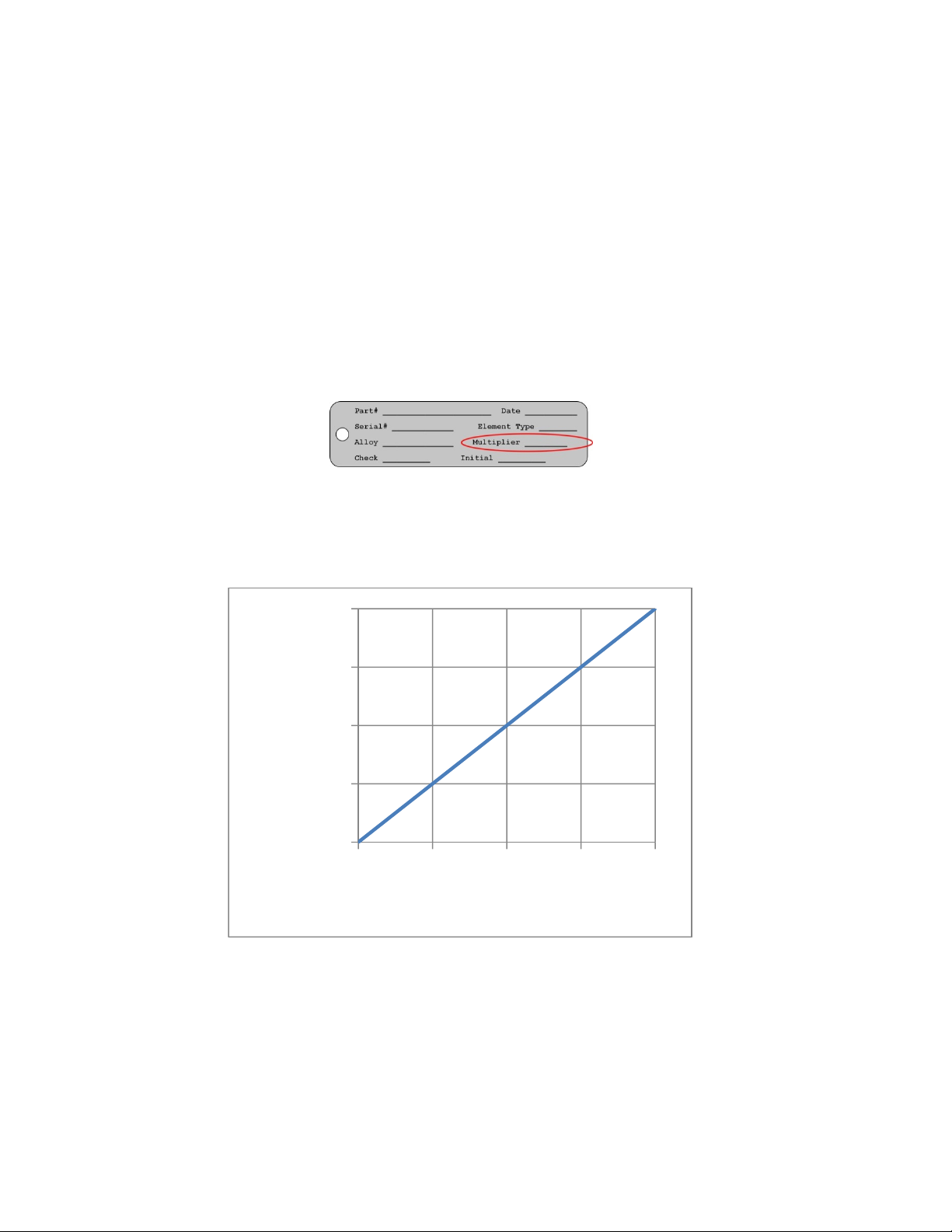
TheProbeLifecanbefoundinTable1andisalsolistedontheMetalSamplesprobetag(asthe
“Multiplier”.)
Figure6.MetalSamplesProbeTag
Figure7illustratestherelationshipbetweenthedigitaloutputandMetalLoss.Inthisexamplea
probewitha10‐millifeisassumed.However,theXaxiscouldbechangedtorepresentanyProbeLife.
Figure7.OutputRelationship
Asseenhere,thetransmitteroutputbeginsat0foranewprobe(zeroMetalLoss)andincreasesas
theprobeelementcorrodes,eventuallyreachingamaximumof65535whentheprobesensing
elementhasbeencompletelyconsumedbycorrosion(inthiscase,10milsofMetalLoss.)Atthistime
theprobehasreacheditsend‐of‐lifeandmustbereplaced.
0
16384
32768
49151
65535
0.0 2.5 5.0 7.5 10.0
RS‐485ModbusOutput
MetalLoss(mils)
New
Probe
Probe
Consumed

14
ii.CalculatingCorrosionRate
Asexplainedpreviously,ERprobesandinstrumentsreportMetalLoss.However,thevaluethatisof
ultimateinterestisCorrosionRate.TheCorrosionRateisessentiallyMetalLossovertime,sothe
CorrosionRatecanbecalculatedusingthefollowingformula:
CorrosionRatempy ∆MetalLossmils
∆Timedays 365
where:
∆MetalLoss(mils)isthedifferencebetweentwoMetalLossreadings
Time(days)isthetimedifferencebetweenthosetworeadings
Itisacommonpracticetoprogramthisformulaintothecontrol(DCS/PLC)systemandhaveit
calculateCorrosionRateonacontinualbasisfromtheMetalLossdata.Thechallengeindoingthisis
selectinganappropriatetimeinterval.Usinganintervalthatistooshortmaygiveerraticresults,
whileselectinganintervalthatistoolongmaygiveresultsthatareinsensitivetosystemupsets.The
idealtimeperioddependsonmanyfactors,andwillvaryfromsystemtosystem.Itmaytakesome
trialanderrortosettleonthebesttimeperiodforyourinstallation.
InsomecasesitmaybenecessarytoreviewtherawMetalLossdataandmanuallyapplythe
CorrosionRateformulatoperiodsofinterest.Forexample,lookatthegraphbelowandseehow
muchthecalculatedCorrosionRatecanvarydependingonthetimeperiodused.
Figure8.CorrosionRatescalculatedfromMetalLossdata
Whileeachoftheresultsisvalidfortheselectedtimeperiod,theoneofmostinterestisthevalueof
11.81mpywhichrepresentssometypeofsystemupset.WhentheCorrosionRateiscalculated
automaticallyonapre‐selectedtimeperiod,thereisnoguaranteethattheselectedtimeperiodwill
alwayscoincidewithsystemupsetssuchasthis.Thatiswhymanualreviewandinterpretationof
MetalLossdataisalsohelpful.

15
e.Commissioning
OncetheMS2700E transmitterhasbeeninstalled,tested,andproperlyconfiguredfortheprobeinuse,it
canthenbeclosedandputintoservice.First,performonelastvisualinspectiontoensurethatall
electricalconnectionsaresecureandthattheenclosureo‐ringisinplaceandisingoodcondition.Then
threadtheenclosurelidontothebasefully.Oncethelidhasbeenthreadedintoplace,tightentheLock
Screwtopreventunauthorizedtampering.
Figure9.EnclosureLockScrew
CAUTION:TheLockScrewontheinstrumentbasemustbetightenedsecurelytopreventunauthorized
personnelfromopeningtheMS2700E
transmitter,andensurethattheintrinsicsafetyisnotviolated.Only
qualifiedpersonnelshouldbeallowedtoinstall,operate,andmaintenancetheMS2700E
transmitter.
C.Maintenance
Onceinstalled,theMS2700E transmitterrequireslittlemaintenance.However,itisimportanttoverifythe
followingitemsperiodicallytoensurecontinuedsafeoperation.
CAUTION:BeforeperforminganytestsormaintenanceontheMS2700E
transmitter,ensurethatall
hazardousarearequirementsaremet.
InspectionItemFrequency
Inspecttheenclosureo‐ringforanysignsofdamage.Replaceasnecessary.Annually
Inspecttheprobeconnectoro‐ringforanysignsofdamage.Replaceasnecessary.Annually
Inspecttheexternalelectricalconnectionsforsignsofcorrosion,mechanicaldamage,or
foreignmatterthatcouldcausedamageorcauseanelectricalshort.Cleanasnecessary.
Annually
Ensurethatthelockingscrewisinplaceandissecure.Annually
TheMS2700E transmitterenclosureismadeofcorrosion‐resistant316stainlesssteel.
However,itshouldstillbecheckedperiodicallyforanysignsofcorrosion.
Annually
Checkforanysignsofmoistureingresswithintheenclosure.Annually
ContactMetalSamplesforreplacementpartsorifinstrumentrepairisnecessary.

16
D.Troubleshooting
IftheMS2700E transmitterdoesnotseemtoperformasexpected,checkthefollowingitems:
CAUTION:BeforeperforminganytestsormaintenanceontheMS2700E
transmitter,ensurethatall
hazardousarearequirementsaremet.
1. Ensurethattheprobeisoperationalandisnotcompletelycorroded.Thiscanbedoneintwoways.
a. TesttheprobewithaportableERmeterifavailable.
b. Testtheprobewithaportableresistanceorcontinuitymeterasfollows:
i. Connectonetestleadtopin‘A’oftheprobes6‐pinconnector.
ii. Measurecontinuitytoeachoftheotherpins.Thereshouldbecontinuity(low
resistance)toeachpin.
NOTE:Continuityoneachpindoesnotensurethattheprobeisgood.However,ifyou
findanopencircuitonanypinsthenitisalmostcertainthattheprobeisbadandshould
bereplaced.
2. EnsurethattheProbeSelectionSwitchesaresetcorrectlyfortheprobebeingused.Confirmthe
probetypeandrefertoTable2onpage9toverifytheappropriateswitchsettings.
3. Performavisualinspectionofthecircuitboardstolookforanysignsofmechanicalorelectrical
damage.
4. Ensurethatallelectricalcablesandwiringareingoodcondition.
5. Ensurethatallelectricalcontactsaresecureandfreeofcorrosion.
6. Ensurethatthereisadequatesupplyvoltageatthepowerconnector.
7. Verifythatthesupplyvoltagepolarityiscorrect.
8. Ifthereisinsufficientsupplyvoltageonthepowerconnector,checkthesafetybarrier(if
applicable)forablownfuseoranyotherfailure.
9. TesttheMS2700E transmitterusingthesuppliedMeterProver(seepage12.)
Thesebasicchecksshouldindicatethesourceofanyproblem(probe,powersupply,wiring,etc.).Ifitis
determinedthattheMS2700E transmitterismalfunctioning,orifyouneedfurtherassistancein
troubleshooting,contactMetalSamplesTechnicalSupport.
CAUTION:IftheMS2700E transmittershowsanysignsofdamage,removeitfromserviceimmediatelyand
consultthefactory.
Table of contents
Other Metal Samples Transmitter manuals

Metal Samples
Metal Samples CORR Velox MS2800E User manual

Metal Samples
Metal Samples MS2701E User manual

Metal Samples
Metal Samples MS2500L User manual

Metal Samples
Metal Samples MS2601E User manual

Metal Samples
Metal Samples MS2901E User manual

Metal Samples
Metal Samples MS2600E User manual

Metal Samples
Metal Samples CORR VELOX MS2801E User manual

Metal Samples
Metal Samples MS2500E User manual


