Healthmark 9060 User manual

Instructions for Use: Spray Gun #9060
Brand Name of Product
Spray Gun
Generic Name of Product
Spray Gun
Product Code Number(s)
9060
Intended Use
For use in the cleaning of items with water or air.
Range of Applications for Product
N/A
Key Specifications of Product
●Use with the “universal” slip-tip, or the optional quick connect set of tips for
specialized functions.
●Maximum water or air pressure 12 bar (172 psi).
Shipping & Storage
Shipping Conditions &
Requirements
N/A
Storage Conditions
N/A
Packaging Contents
N/A
Shelf Life
N/A
Instructions for Using Product
Description of Use(s)
A tool to use in the cleaning of items with water or air.
Preparation for Use
●Best installed by a licensed plumber. Please contact Facilities and/or
Engineering for installation of the spray gun. Installation of the spray gun is
done by the facility.
●Connection requirements
oWater connection:
▪Plumbing threaded tap or valve: 3/8-, 1/2- or 3/4-inch
▪Standard gun kit includes 3/4-inch female connection.
oAir connection:
▪If operated with compressed air, the tubing must be connected
to the air supply by a suitable connector (Note: Cannot be
supplied by Healthmark).
▪When connecting the gun to water or air below the counter, it
is recommended that a rosette be installed.
●The rosette will minimize potential friction damage to
the hose.
●Drill a 1 3/8inches diameter hole in the counter or
sink top to accommodate the rosette.
●Prior to operation, ensure attachments are correctly seated on the safety cone.
●If the spray gun is not in use, it must be assured the water or air pressure have
been turned off.
●When the hose of the Spray Gun is installed to the water line, a separate shutoff
valve needs to be installed to the spigot. (Note: The spray gun is not a
controller.)
Diagrams (drawings, pictures)
Document
Version
1
Figure 1: 9060 Spray Gun
Figure 2: 9060 Tip Attachments
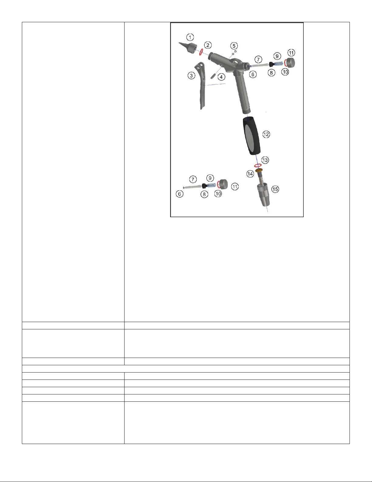
Key to Spray Gun Components
1. Gun Rinser Tip Holder complete kit
2. “O” Ring black 3 mm x 1-mm
3. Spiral Tension Pin
4. Trigger Handle
5. Grip for Spray Gun
6. Hose Connector
7. Gun Cap
8. Flow Control Kit
Figure 3: Flow Rate Controlled by Trigger handle
Steps for Use of Product
1. Prior to operation, ensure attachments are correctly seated on the safety cone by
firmly pushing them onto the spray gun rinse tip. Make sure the valve is open
that is attached to the hose.
When in operation:
2. Do not point the Spray Gun at parts or orifices of the body. Compressed water or
air jet may be harmful.
3. Wear the proper PPE according to facility policy.
4. (If required), adjust the maximum water or air pressure value using the small
threaded nut located behind the trigger handle.
Interpretation of Test Results
N/A
Contraindications of Test Results
N/A
Documentation
N/A
Special Warnings and Cautions
●Facilities should independently verify any tubing for safe and effective
performance that is not supplied by Healthmark. (Note: The liability for damage
or injury is the responsibility of the facility.)
●Warranty claims will only be honored for components purchased from
Healthmark.
●Do not use the Spray Gun for any medical treatments.
Before Operating:
●Ensure attachments are correctly seated to the body of the Spray Gun.
●Maximum water or air pressure to use is 12 bar (172 psi).
During Operation:
●Wear proper PPE according to facility policy.
●Do not point the Spray Gun at parts or orifices of the body. Compressed water or
air jet may be harmful.
●
When Not Operating:
●If Spray Gun is not in use, it must be assured water or air pressure have been
turned off and the system is depressurized.
●Cleaning and sterilization must be carried out by qualified personnel.
●Cleaning guns must not be reused if still contaminated with pathogens after
using the sterilization procedure.
Disposal
N/A
Reprocessing Instructions
Point of Use
N/A
Preparation for Decontamination
1. Turn off water connection/compressed air and completely empty the cleaning
gun and the hose by operating the dosing lever.
2. Disassemble all components.
3. All connections of the cleaning gun must be loosened by hand.
4. The water supply must be interrupted before dismantling and the residual
pressure must be released by operating the dosing lever to leave the system
depressurized.
5. Carefully remove all silicone O-rings from their positions:
1. Hose
attachment
2. O-ring
3. Dosing trigger
Document
Version
1

4. Trigger axle
5. O-ring
6. O-ring
7. Dosing pin
8. Conical nipple
9. Compression
spring
10. O-ring
11. Sealing cap
12. Silicone handle
13. O-ring
14. Gun spout
15. Holding cone
Hose attachment - Position:
1. Hose attachment – Pos. (1): Turn left to separate the hose attachment from the
gun body.
2. O-Ring - Pos. (2): Remove the O-Ring, if necessary.
3. Sealing cap - Pos. (11): Slowly open the sealing cap by turning the cap to the
left to prevent the dosing spring from jumping out.
4. O-Ring - Pos. (10): Remove the O-Ring from the sealing cap if necessary.
5. Dosing spring - Pos. (9): Remove the dosing spring.
6. Sealing cone - Pos. (8): Remove the sealing cone.
7. Trigger axle - Pos. (4): Push the dosing lever axle completely out of the gun
body with your fingers.
a. If necessary, use the hose attachment as an aid.
b. An additional operation of the dosing lever facilitates the removal.
8. O-Ring - Pos. (5): Remove the O-Ring if necessary.
9. Dosing trigger - Pos. (3): Remove the dosing trigger from the gun body.
10. Dosing pin - Pos. (7): Remove the dosing pin, the axle can be used as an
instrument to facilitate the removal.
11. O-Ring - Pos. (6): Remove the O-Ring if necessary.
12. Holding cone - Pos. (1) (5): Separate the holding cone from the gun spout and
gun body by turning it to the left.
13. O-Ring - Pos. (1) (3): Remove the O-Ring if necessary.
14. Silicone handle - Pos. (1) (2): Pull the silicone handle off the gun body.
Disassembly Instructions
N/A
Cleaning – Manual
Cleaning Instructions:
The Spray Gun must be cleaned by trained personnel in accordance with the applicable
hygiene plan. It must be cleaned with a pH neutral detergent and rinsed with sufficient
warm water.
1. Place the individual parts in the detergent and observe the specified contact time.
All components must be completely covered with detergent (both inside and
Document
Version
1

outside) including the cavities of the Spray Gun. The components must be
cleaned with a non-linting wipe, sponge, or brush.
2. Place the individual components in the ultrasonic and observe the compatibility
of the ultrasonic cleaner and the contact time.
3. Rinse off the cleaning gun and the components with sufficient water and remove
any remaining detergent residue.
4. Dry the outside and inside with a non-linting wipe; use a medical compressed
air.
Cleaning – Automated
In addition to manual cleaning, the Spray Gun can be put into the automated washer.
Disinfection
N/A
Drying
N/A
Maintenance, Inspection, and
Testing
●It is recommended to decalcify the Spray Gun approximately when needed.
oDisassemble the gun and place the inner parts into a decalcifying agent.
oThis is beneficial for the service life and reliability of the Spray Gun.
●It is not necessary to carry out water quality tests in the case of using potable
water.
●Replacement parts and instructions for repair are available from Healthmark.
●Component Warranty:
oStainless-steel parts have a one (1)-year warranty.
oO-Rings are worn parts and do not fall under warranty.
oIn the event of improper intervention of the mechanical components of
the cleaning gun, the statutory guarantee and warranty claims expire.
Reassembly Instructions
Reassembly of the Spray Gun after sterilization:
The complete assembly of the cleaning gun must be carried out under sterile conditions.
Before screwing the individual parts together, make sure all O-Rings are in
perfect condition.
Sealing elements must be moistened with a suitable physiological saline solution
before use.
Sealing rings are to be mounted at the intended locations and locked in place by
pressing them firmly by hand.
1. O-Ring - Pos. (2): Place the moistened O-Ring on the attachment Pos. (1).
2. Hose attachment - Pos. (1): Screw the attachment to the gun body by turning it
clockwise.
3. Dosing trigger - Pos. (3): Attach the dosing trigger to the gun body.
4. Dosing lever axle - Pos. (4): Use your fingers to completely push the dosing
lever axle into the gun body to lock the dosing lever. An additional operation of
the dosing trigger facilitates the movement.
5. Dosing pin - Pos. (7): Insert dosing pin with moistened (O-Ring 3 x 1 mm) into
the gun body. If necessary, press the dosing pin with your finger to prevent it
from falling out. (Attention: If the dosing pin is inserted with force, the O-Ring
may be damaged and the gun may leak at the dosing pin position.)
6. Sealing cone - Pos. (8): Insert the sealing cone into the gun body with the short
side facing toward the gun.
7. Dosing spring - Pos. (7): Place the dosing spring on the long side of the sealing
cone and insert it into the gun body.
8. O-Ring - Pos. (10): Put the moistened O-Ring on the sealing cap Pos.: (1,1) and
push it into the intended position.
9. Sealing cap - Pos. (1, 1): Turn the cap clockwise to carefully screw it onto the
gun body against the pressure of the dosing spring.
10. Silicone handle - Pos. (1, 2): Put the silicone handle on the gun body. The
inscription must point to the front as shown in the illustration.
11. O-Ring - Pos. (1, 3): Put the moistened O-Ring on the gun spout Pos.: (1, 4) and
press it into the intended position.
12. Holding cone - Pos. (1, 5): Screw and tighten the holding cone clockwise with
the hose to the gun body and tighten sufficiently.
Document
Version
1
Leak Test after reassembling:
1. Turn on the water or compressed air supply.
a. Check the Spray Gun visually and acoustically for leaks.
b. Slowly operate the trigger several times over the entire dosing range -
Pos. (3).
c. Check dosing capability and test for leaks on the dosing pin under the
trigger.
2. During each setup, it must be ensured that all connection points of the cleaning
gun are firmly connected and sealed.
3. When not in use or at the end of work, the water supply or compressed air
supply must be disconnected. The Spray Gun must then be left depressurized by
operating the trigger several times.
4. The steps for leak testing must be repeated each time the Spray Gun is put back
into use.
Packaging
N/A
Sterilization
Steam sterilization for the spray gun and components # 9060:
●Place the disassembled cleaning gun and the individual components in the
sterilization container.
●Steam sterilization at 135 ℃for five (5) minutes maximum.
Storage
N/A
Additional Information
N/A
Related Healthmark Products
N/A
Other Product Support Documents
Brochure, Price List
Reference Documents
N/A
Customer Service Contact
Healthmark Industries Company, Inc.
18600 Malyn Blvd.
Fraser, MI 48026
1-586-774-7600
hmark.com
Document
Version
1
Other Healthmark Paint Sprayer manuals


