Metallkraft BMBS 300X320 H-DG User manual
BMBS 300x320 H-DG
Operating Instructions
BMBS 300x320 H-DG
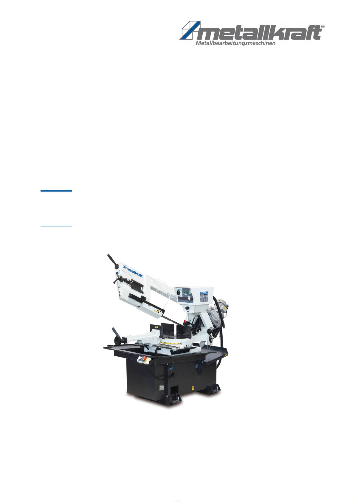
BMBS 300X320
Swivel Frame Metal Bandsaw

2BMBS 300x320 H-DG | Version 1.06
Imprint
Product identification Swivel Frame Metal Bandsaw Item number
BMBS 300x320 H-DG 3680012
Manufacturer Stürmer Maschinen GmbH
Dr.-Robert-Pfleger-Str. 26
D-96103 Hallstadt
Fax: 0049 (0) 951 96555 - 55
E-Mail: [email protected]
Internet: www.metallkraft.de
Indications regarding the operating
instructions
Genuine operating instructions
Edition: 21.06.2019
Version: 1.06
Language: English
Author: SN
Indications regarding the copyright Copyright © 2019 Stürmer Maschinen GmbH, Hallstadt, Germany.
The contents of these operating instructions are the sole property of Stürmer
Maschinen GmbH.
Passing on and reproduction of this document, exploitation and communica-
tion of its contents are prohibited unless expressly permitted.
Contraventions obligate to compensation for damages.
Subject to technical changes and errors.

BMBS 300x320 H-DG | Version 1.06 3
Content 1 Introdiction.................................................................................................4
1.1 Copyright .............................................................................................. 4
1.2 Customer Service ................................................................................. 4
1.3 Limitation of Liability ............................................................................. 5
2 Safety..........................................................................................................5
2.1 Symbol explanation .............................................................................. 5
2.2 Operator responsibility ......................................................................... 6
2.3 Operating staff qualification.................................................................. 7
2.4 Personal protective equipment............................................................. 7
2.5 General safety instructions ................................................................... 8
2.6 Safety labels on the metal bandsaw..................................................... 9
3 Intended Use............................................................................................10
3.1 Improper use ...................................................................................... 11
3.2 Residual risks...................................................................................... 11
4 Technical Data .........................................................................................11
5 Transport, packaging, storage...............................................................12
5.1 Delivery and transport ........................................................................ 12
5.2 Packaging........................................................................................... 14
5.3 Storage ............................................................................................... 14
6 Description of machine...........................................................................14
6.1 Machine components ......................................................................... 14
6.2 Scope of delivery ................................................................................ 15
7 Assembly..................................................................................................16
7.1 Setting up............................................................................................ 16
7.2 Electrical connection .......................................................................... 22
7.3 Filling the coolant lubricant................................................................. 24
7.4 Micro-spraying system ....................................................................... 24
7.5 Bundle clamping unit.......................................................................... 26
7.6 Lighting ............................................................................................... 27
7.7 Roller conveyors ................................................................................. 27
8 Operation..................................................................................................27
8.1 Operating and control elements......................................................... 28
8.2 Adjustments ........................................................................................ 29
8.2.1 Angle setting ................................................................................ 30
8.2.2 Adjustment of the vice.................................................................. 31
8.2.3 Setting the lower working position................................................ 32
8.2.4 Position of the movable band guide............................................. 32
8.2.5 Tensioning the band..................................................................... 33
8.2.6 Cutting speed adjustment............................................................ 33
8.2.7 Saw band cooling and lubrication................................................ 35
8.2.8 Clamping of material .................................................................... 35
8.3 Work flow ............................................................................................ 36
8.4 The factors for optimal operation........................................................ 37
9 Cleaning, maintenance and servicing ...................................................38
9.1 Cleaning.............................................................................................. 38
9.2 Replacing the saw band..................................................................... 39
9.3 Saw blade tensioning device.............................................................. 40
9.4 Adjusting the chip brush..................................................................... 40
9.5 Maintenance of the control cabinet .................................................... 41
9.6 Saw guides ......................................................................................... 41
9.7 Selection of the right saw blade ......................................................... 43
9.8 Maintenance ....................................................................................... 46
9.9 Lubrication plan.................................................................................. 47
9.10 Filling and replacing coolant ............................................................ 48
9.11 Saw band guide clearance............................................................... 49
10 Troubleshooting ....................................................................................49
11 Disposal, recycling of used equipment...............................................50
12 Spare parts.............................................................................................51
13 Electrical circuit diagrams....................................................................71
14 EU Declaration of Confromity ..............................................................74
15 Maintenance schedule ..........................................................................75

4BMBS 300x320 H-DG | Version 1.06
Introdiction
1 Introdiction
You have made a good choice by purchasing the metal bandsaw made by
METALLKRAFT.
Thoroughly read the operating instructions before commissioning the machine.
It informs you about the proper commissioning, the intended use as well as
the safe and efficient operation and maintenance of your metal bandsaw.
The operating instructions are part of the metal bandsaw. Always keep it at
the place of use of the metal bandsaw. Furthermore, the local accident pre-
vention regulations and the general safety notes are applicable for the field of
application of the metal bandsaw.
The illustrations in these operating instructions serve the general comprehen-
sion and may deviate from the actual type.
1.1 Copyright
The contents of these instructions are copyright. Their application is admis-
sible in the frame of the Device utilisation. An application beyond the descri-
bed application is not allowed without written approval of the manufacturer.
For the protection of our products, we shall register trademark, patent and de-
sign rights, as this is possible in individual cases. We strongly oppose any in-
fringement of our intellectual property.
1.2 Customer Service
Please contact your dealer if you have questions on the machine or if you
need technical advice. They will help you with specialist information and ex-
pert advice.
Germany:
Stürmer Maschinen GmbH
Dr.-Robert-Pfleger-Str. 26
D-96103 Hallstadt
Repair Service:
Fax: 0049 (0) 951 96555-111
E-Mail: [email protected]
Spare part orders:
Fax: 0049 (0) 951 96555-119
E-Mail: ersatzteile@stuermer-maschinen.de
We are always interested in valuable experience and knowledge gained from
using the application, which then could be shared and be valuable to develop
our products even further.

Safety
BMBS 300x320 H-DG | Version 1.06 5
1.3 Limitation of Liability
All information and notes in these operating instructions were summarised ta-
king the applicable standards and rules, the state-of-the-art and our long-
term knowledge and experiences into consideration.
The following cases the manufacturer is not liable for damages:
- Non-observance of the operating instructions,
- Inappropriate use,
- Use of untrained staff,
- Unauthorised modifications,
- Technical changes,
- Use of not allowed spare parts.
The actual scope of delivery may deviate from the explanations and presenta-
tions described here in case of special models, when using additional orde-
ring options or due to latest technical modifications.
The obligations agreed in the delivery contract, the general terms and condi-
tions as well as the delivery conditions of the manufacturer and the legal regu-
lations at the time of the conclusion of the contract are applicable.
2 Safety
This paragraph will give you an overview of all important safety packages for
the protection of the people using it well as for a safe and undisturbed opera-
tion. Other task-based safety notes are included in the individual chapters.
2.1 Symbol explanation
Safety Instructions The safety notes in these operating instructions are high-lighted by symbols.
The safety notes are introduced by signal words which express the concern
of the risk.
DANGER!
This combination of symbol and signal words indicates an
imminently dangerous situation which may lead to death or
severe injuries if they are not avoided.
WARNING!
This combination of symbol and signal words indicates a
possibly dangerous situation which may lead to minor or
light injuries if they are not avoided.
ATTENTION!
This combination of symbol and signal words indicates a
possibly dangerous situation which may lead to property
and environmental damages if they are not avoided.
CAUTION!
This combination of symbol and signal term indicates a
potentially hazardous situation which may cause minor or
light injuries if it is not averted.
This manual suits for next models
1
Table of contents
Other Metallkraft Saw manuals


