METALpro MP9500 User manual
OPERATIONS MANUAL
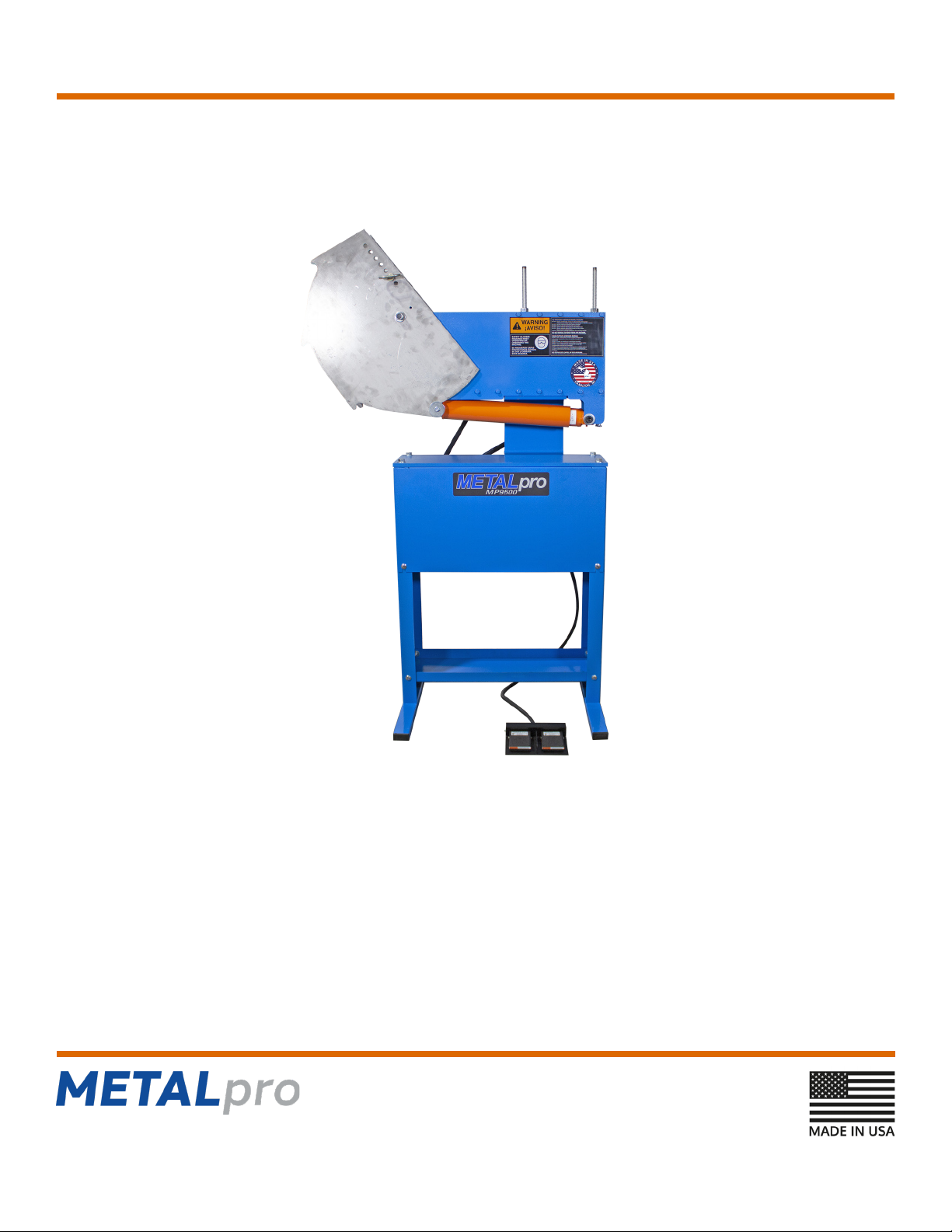
MP9500 Bender
4715 136th Avenue, Hamilton, MI 49419
(262) 679-0504
metalprocorp.com
More metal fabrication for your money
August 2022

MP9500 Bender More metal fabrication for your money
TABLE OF CONTENTS
Introduction.....................................................................1
Warranty .........................................................................1
Return and Refund Policy...............................................1
Safety .............................................................................2
Unboxing and Installation Process .................................2
Machine Description.......................................................3
Dimensions.....................................................................4
Capacity..........................................................................4
Specications .................................................................4
Hardware and Components............................................4
Bill of Material.................................................................5 - 6
Tube and Pipe Die Sets..................................................7 - 9
Leg Stand Assembly.......................................................9
Bender Head Assembly..................................................10
Hydraulic Installation ......................................................11
Bender Die Installation ...................................................12 - 13
Bending Tube and Pipe ..................................................14 - 16
Bending Instructions and Terminology............................16 - 18
Tube Usage ....................................................................19 - 20
Maintenance...................................................................21
(262) 679-0504 metalprocorp.com

MP9500 Bender More metal fabrication for your money
INTRODUCTION
This manual provides the information required for assembling, setting up, operating, and maintaining the MP9500 Bender. Included as
a part of this manual are a replacement parts lists and assembly illustrations to guide you.
Included in manual are the specications and capabilities of the Bender. If you have questions regarding the capabilities of the
MP9500 Bender for a new application or need assistance in determining tooling requirements, please contact us at:
Metalpro Corporation
4715 136th Avenue
Hamilton, MI 49419
(262) 679-0504
The rst several pages of this manual view safety and cautionary information. This safety section summarizes the design safety
elements, reviews WARNINGS, and lists the WARNING labels on the machine and accessories. It is your responsibility to understand
all WARNINGS.
Observe all WARNINGS and CAUTIONS during installation, operation, servicing, and maintenance of the MP9500 Bender.
WARRANTY INFORMATION
Metalpro Corporation (seller) will, within one (1) year from date of purchase replace F.O.B. the factory, any goods which are defective in
materials and/or workmanship provided the buyer, at the seller’s option, return the defective goods prepaid to the seller. Punches, dies,
and/or blades are warranted to be free of defects in materials and workmanship with thirty (30) days of purchase date.
This warranty does not apply to machines and/or components that have been altered, changed, modied in any way, subjected
to abuse, abnormal use, inadequate maintenance, and lubrication, or subjected to use beyond recommended capacities and
specications. In no event shall the seller be liable for labor costs expended on such goods or consequential damages. Seller shall
not be liable to purchaser or any other person for loss or damage directly or indirectly arising from the use of the goods, from any
representations or warranty of tness, or to waive any of the foregoing terms of sale, and none shall be binding on the seller.
This warranty is non-transferable.
RETURN AND REFUND POLICY
METALpro oers a 1-year limited manufacturing warranty on all METALpro machines from manufacturing defects.
• The Buyer has 30 days from date of delivery to contact the Seller regarding a return
• All METALpro returns are subject to a 20% restock fee
• The Buyer is responsible for shipping item back to METALpro at 4715 136th Ave Hamilton, MI 49419 and providing pictures showing
condition of product before it ships
• The product needs to be in new/unused condition and be in original METALpro packaging for resale
• If not, Buyer is liable for cost to repair and repackage item additional to the 20% restock fee
• All returns are subject to METALpro’s inspection at time of delivery
Any questions or concerns please contact METALpro’s Customer Service at (262)-679-0504.
page 1(262) 679-0504 metalprocorp.com

MP9500 Bender
page 2
More metal fabrication for your money
SAFETY
To prevent serious bodily injury:
• Do not operate, install tooling, service, or adjust machine without proper instructions and without reading and understanding the
operations manual.
• Do not service the machine with the electrical power connected.
• Do not operate machine without all dies properly seated, pinned, and fastened.
• Do not loosen the lock nut tensioning to the sunbursts without rst disengaging the cylinder and rotating the sunbursts to
the “down” position. This is when the at edges are parallel to the oor (Figure 7 on page 13).
• Do not bend pipe or tubing without the feed cage properly positioned and secured.
• Do get help to install the large and heavy rotating dies
• Do stand clear of the pipe, tubing, and other material during the bending operation
• Do make sure that the sunburst pusher properly seats in the sunbursts during the bending operation.
SAFETY SUMMARY
• Wear approved eye protection when using the MP9500 Bender.
• Observe and follow the WARNINGS displayed on the MP9500 Bender and keep hands and clothing clear of all moving parts.
• The bending operation will cause the end of the tubing to rotate upward. Make sure there is clearance for this movement. Keep
your hands and clothing clear of the pipe as it is bent.
• Before doing any repairs on the MP9500 Bender, make sure it is unplugged.
• Any OSHA guarding requirements are the responsibility of the purchaser
UNCRATING, INSPECTION, ASSEMBLY, AND INSTALLATION
For assembly and installation, refer to the exploded views as well as the bill of materials.
• Using a forklift or pallet jack, move the crated MP9500 Bender as close as practical to the workstation where the Bender will be
assembled and installed.
• Uncrate the Bender.
• Make sure the instructional material and the packing list are preserved and that all components are accounted for prior to discarding
the shipping crate.
• Carefully inspect the Bender. Make sure all items listed on the packing list are present.
• If damage is discovered, report the nature of the damage to the carrier. Replace any damaged components before using
the bender.
• The installation site should be level.
• Tools required
– adjustable wrench
– " wrench – " socket
– " socket – " socket
– " wrench – " - " hex or T-handle wrench set
(262) 679-0504 metalprocorp.com
MP9500 Bender
page 3
More metal fabrication for your money
DESCRIPTION
The MP9500 Bender is a multipurpose rotary bending machine. The straightforward design allows for quick set-up and
ease of use.
Each size of tubing or pipe to be bent requires three die components, the rotating die, the stationary die and the moving die. The
rotating dies are cylindrical with a raised edge (for square tubing) or one, two or three half round grooves (for round tubing) around the
circumference. The stationary dies are rectangular blocks with a tapered rectangular groove (for square tubing) or one, two or three
half round grooves (for round tubing). The moving dies are also rectangular blocks with a rectangular groove (for square tubing) or one,
two or three grooves (for round tubing).
The moving die, which is held between the sunbursts by a hitch pin, grips and pulls the tubing through the stationary die as the
sunbursts rotate. The gripping is aided by set screws (square tubing) or set collars (round tubing and pipe). The rotation of the
sunbursts is caused by the extension of the cylinder rod. The stationary die keeps the tubing positioned as it is pulled to be formed.
The tubing is formed against the rotating die.
The MP9500 Bender is a single stroke machine. The foot switch controls stroke direction. When the foot switch pedal is held in
one direction, the bender cylinder rod will travel in that direction and will stop only if the pedal is released, or the maximum stroke is
reached. Note: Four strokes of the cylinder are required to bend the full 180 degrees.
(262) 679-0504 metalprocorp.com
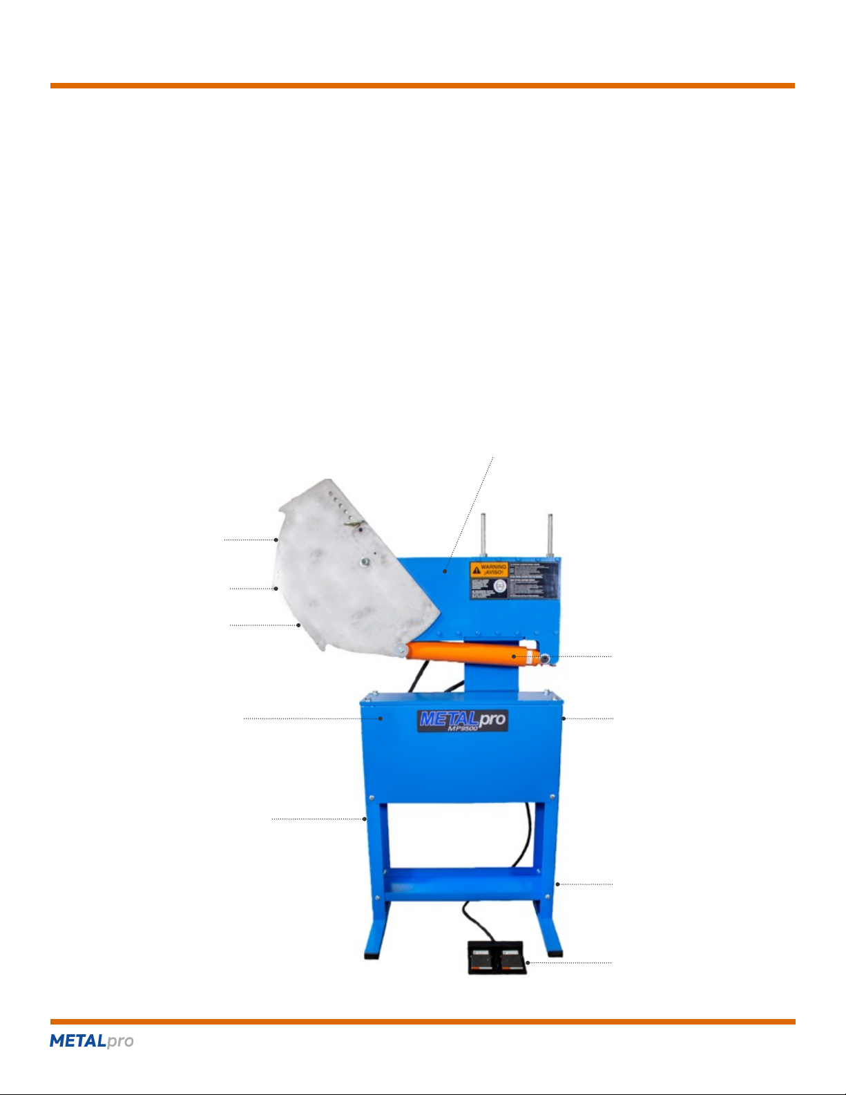
side plate
sunbursts
rotating die
(between sunburst)
moving die
(between sunburst)
foot switch
lower shelf
cylinder
motor, pump, valve
and reservoir
behind cover
control valve
(back side)
leg stand

MP9500 Bender
page 4
More metal fabrication for your money
DIMENSIONS AND WEIGHT
Width: 40 Inches
Height: 66 Inches
Depth: 24 Inches
Weight: Approximately 325 lbs. and includes packaging
OPERATIONAL CAPACITY
Approximately 4 to 5 strokes per minute for the smallest pipe
Maximum force 12 Tons
BENDER CAPACITY
The MP9500 Bender easily handles a wide variety of professional, farm, and industrial production jobs. Using dierent dies, the
machine can bend " up to 2" square tubing, " to 2" round tubing and " to 1 " pipe up to 180 degrees.
Call METALpro customer service to discuss specic requirements.
SPECIFICATIONS
Electrical Requirement 110V, 20 amp service
Hydraulic Power Self-contained, 2500 psi
HARDWARE AND COMPONENTS
Item Description Qty
42 -18 x " carriage bolt ..............10
43 -18 lock nut ......................10
44 " at washer ......................10
45 -13 x 1 " hex head screw ...........4
47 " at washer ......................4
48 " lock nut .........................4
13 " x 3 " pin........................2
14 " die/sunburst install pin .............1
15 " x 6 " hitch pin with bridge pin .......1
60 -16 x " hex head screw ............2
65 " at washer ......................2
95 cylinder hold clamp. . . . . . . . . . . . . . . . . . . 1
100 -11 x 4" threaded rod ...............2
Above items are packed in a bag
(262) 679-0504 metalprocorp.com
Item Description Qty
Bender Head Assembly ....................1
(includes items 1, 2, 9, 10,11, 12, 24, 34,
35, 36, 37, 40, 41, 46, 53, 55, 56, 57, 58,
59, 60, 61, 62, 63, 64, 65, 66, 96, 97, 98,
99, 101, 102)
3 Sunburst ................................2
4 Front Panel..............................1
6 Lower Shelf .............................1
Upper Shelf Assembly .....................1
(includes items: 5, 7, 17, 18, 19, 20, 21,
22, 23, 25, 26, 27, 28, 29, 30, 31, 32, 33,
39, 41, 42, 43, 49, 50, 51, 52, 54, 55)
8 Leg (includes item 38) .....................2

MP9500 Bender
page 5
More metal fabrication for your money
BILL OF MATERIAL
Item MP Number Description Qty
1 1004 bender head mounting plate .................1
2 1002 side plate ................................2
3 1003 sunburst .................................2
4 5062 front panel ...............................1
5 5061 reservoir cover ............................1
6 5057 lower shelf ...............................1
7 5058 upper shelf ...............................1
8 5059 leg .....................................2
9 1001 bottom plate ..............................1
10 1000 top plate .................................1
11 1007 tube gauge...............................1
12 1006 sunburst pusher ...........................1
13 1023 " x 3 " pin .............................2
14 1024 " die/sunburst install pin ...................1
15 1022 " x 6 " hitch pin w/bridge pin ...............1
24 1005 hydraulic cylinder (2" bore x 12" stroke) ........1
26 5051 " x 31" hydraulic hose assembly.............2
34 1010 3" diameter x " Teon disc .................2
35 1025 3" diameter x " urethane disc...............2
36 1026 spring guide ..............................2
37 1009 spring 1" od x 2 " lg........................2
38 5039 plastic end cap............................4
39 5022 -16 x 1" hex head screw ..................4
40 1013 -16 x 1 " hex head screw.................1
41 5023 " lock washer ...........................5
42 5031 -18 x " carriage bolt ...................14
43 5032 -18 lock nut...........................14
44 5017 " at washer...........................10
45 5011 -13 x 1 " hex head screw .................4
46 7021 -13 x 1 at head screw ..................4
47 5012 " at washer ............................4
48 5065 -13 lock nut ............................4
49 7029 -20 x " hex head screw ..................8
50 5038 -20 lock nut ...........................10
51 5037 " at washer ............................2
52 5036 -20 x 2" hex head screw ..................2
53 5018 -18 x " hex head screw ................24
54 7031 -18 x 3" hex head screw..................4
55 5033 " lock washer ..........................28
56 1014 " x 4 " shoulder bolt......................1
57 1015 " x 3 " shoulder bolt. . . . . . . . . . . . . . . . . . . . . .1
58 1016 -11 lock nut ............................2
59 1019 " at washer ............................2
60 5025 -16 x " hex head screw..................4
61 1020 " id x 2" od at washer ....................2
62 1018 " at washer ............................4
63 1027 -16 x 4" hex head screw ..................2
64 5019 -16 lock nut ............................2
65 5020 " at washer ............................4
66 1008 magnetic gauge ...........................1
(262) 679-0504 metalprocorp.com

MP9500 Bender
page 6
More metal fabrication for your money
BILL OF MATERIAL (CONTINUED)
Item MP Number Description Qty
90 see pages 7 & 8 rotating die ...............................1
91 see pages 7 & 8 stationary die .............................1
92 see pages 7 & 8 moving die ...............................1
93 1028 -20 x " socket head set screw.............2
94 5028 -16 x " socket head set screw ............2
95 1029 cylinder hold clamp ........................1
96 1030 feed cage side plate........................2
97 1031 feed cage top plate ........................1
98 1032 feed cage roller pin ........................9
99 1033 -11 x 7 " threaded rod ...................2
100 1036 -11 x 4" threaded rod .....................2
101 1035 -18 x " socket at head screw ............8
102 1034 -11 hex nut.............................6
6026 dual foot switch ...........................1
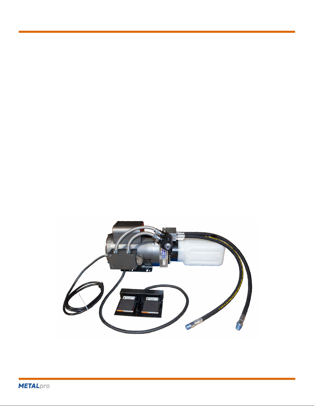
6062 pump/motor assembly 110V .................1
(262) 679-0504 metalprocorp.com

MP9500 Bender
page 7
More metal fabrication for your money
TUBING DIE SET
Tube Size MP Number Description C/L Radius Min Wall Max Wall Weight
", ", " 9500 ", ", " round rotating die 3" .035/.049/.049 .187/.187/.187 20
9520 ", ", " round stationery die any 6
9540 ", ", " round moving die any 8
", 1" 9501 ", 1" round rotating die 3" .065/.083 0.187 19
9502 ", 1" round rotating die 4" .049/.065 0.187 36
9521 ", 1" round stationery die any 6
9541 ", 1" round moving die any 8
1", 1 " 9503 1", 1 " round rotating die 4" .065/.095 0.187 33
9504 1", 1 " round rotating die 5" .049/.083 0.187 53
9522 1", 1 " round stationery die any 5
9542 1", 1 " round moving die any 7
1 ", 1 " 9505 1 ", 1 " round rotating die 5" .065/.083 0.187 54
9506 1 ", 1 " round rotating die 6" .049/.065 0.187 80
9523 1 ", 1 " round stationery die any 6
9543 1 ", 1 " round moving die any 7
1 " 9507 1 " round rotating die 5" 0.109 0.187 80
9508 1 " round rotating die 6" 0.095 0.187 83
9524 1 " round stationery die any 6
9544 1 " round moving die any 7
1 " 9509 1 " round rotating die 5" 0.120 0.187 53
9510 1 " round rotating die 6" 0.109 0.187 79
9525 1 " round stationery die any 5
9545 1 " round moving die any 7
2" 9511 2" round rotating die 6" 0.120 0.187 76
9526 2" round stationery die any 5
9546 2" round moving die any 7
9720 Tubing die set 291
includes 9500, 9502, 9504, 9505 & 9508 round rotating dies
9520,9521,9522,9523,9524 round stationery dies
9540, 9541, 9542, 9543 & 9544 round moving dies
(262) 679-0504 metalprocorp.com

MP9500 Bender
page 8
More metal fabrication for your money
PIPING DIE SET
Pipe Size MP Number Description C/L Radius Min Wall Max Wall Weight
", " 9550 ", " pipe rotating die 3" Schedule 40 Schedule 80 19
9551 ", " pipe stationery die any 6
9552 ", " pipe moving die any 8
", 1" 9553 ", 1" pipe rotating die 4" Schedule 40 Schedule 80 33
9554 ", 1" pipe stationery die any 5
9555 ", 1" pipe moving die any 7
1 " 9556 1 " pipe rotating die 5" Schedule 40 Schedule 80 54
9557 1 " pipe stationery die any 5
9558 1 " pipe moving die any 7
1 " 9559 1 " pipe rotating die 6" Schedule 40 Schedule 80 77
9566 1 " pipe stationery die any 5
9567 1 " pipe moving die any 7
2" 9565 2" pipe rotating die 7" 84
9568 2" pipe stationery die 4
9569 2" pipe moving die 6
9710 Pipe Die Set 233
includes 9550, 9553, 9556 & 9559 pipe rotating dies
9551, 9554,9557 & 9566 pipe stationery dies
9552, 9555, 9558 & 9567 pipe moving dies
(262) 679-0504 metalprocorp.com
MP9500 Bender
page 9
More metal fabrication for your money
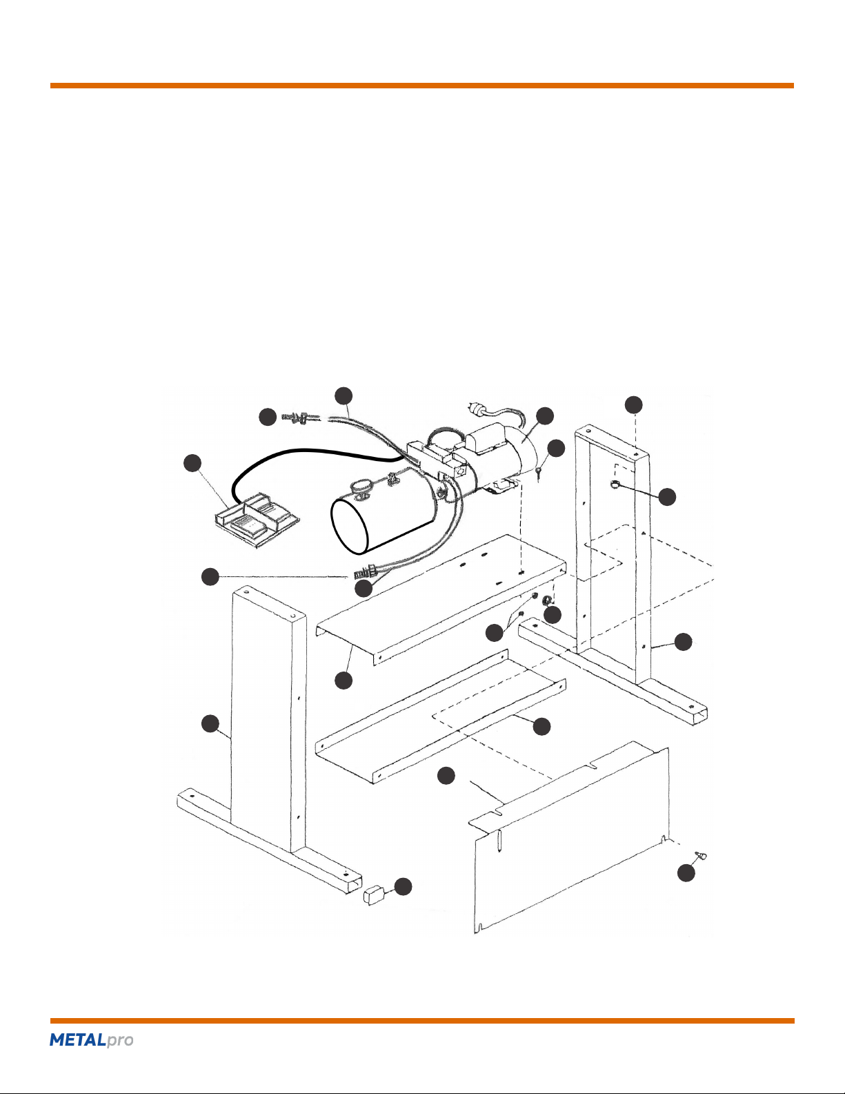
LEG STAND ASSEMBLY – Refer to Figure 1
Step 1: Place the two legs (59) on edge and position the lower shelf (57) and the upper shelf (58) with pump/motor assembly
between them.
Step 2: Install -18 x ¾¾" carriage bolts (31), " at washers (17), and -18 lock nuts (32) hand tight.
Step 3: Set the base upright. Put the dual foot switch (108) on the lower shelf (57).
Step 4: Viewed from the operating side of the Ironworker, the motor will be at the right side of the base.
Step 5: Make sure the legs and the shelves are properly positioned and square. Tighten the lock nuts on the backside of the
bender. Leave the lock nuts on the front side hand tight until the front panel (62) is installed.
(262) 679-0504 metalprocorp.com
109
31
32
17
65
31
57
58
108
39
62
59
59
B
A
51
51
X
FIGURE 1:
LEG STAND ASSEMBLY

MP9500 Bender
page 10
More metal fabrication for your money
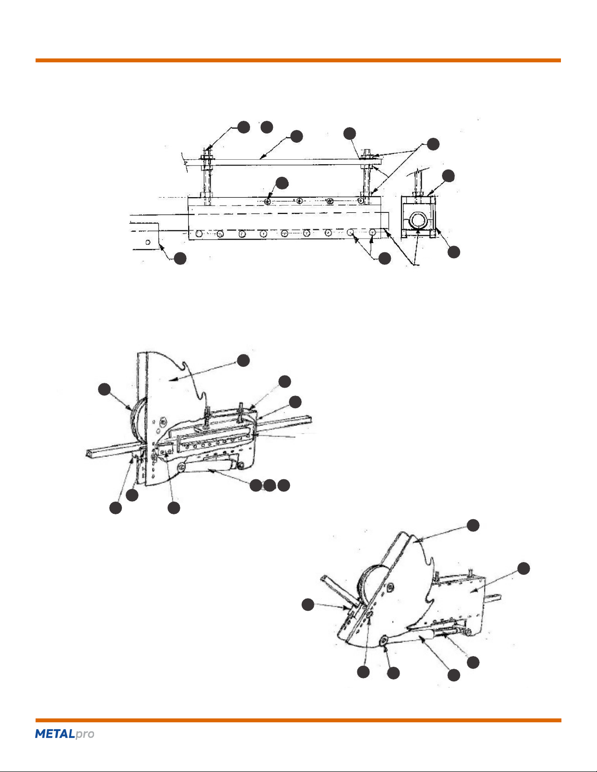
BENDER HEAD ASSEMBLY – Refer to Figure 2
Step 1: Lift and position the bender head assembly over the leg stand assembly on top of the leg stand assembly. Lower the bender
head until it is properly positioned and resting on the base. As viewed from the operating side of the tubing bender, the motor
will be at the right side of the leg stand assembly.
Step 2: Before removing the lifting strap, install four -13 x 1 " hex head screws (45), " at washers (47), and
-13 lock nuts (48) hand tight.
Step 3: Position the front panel (4), (Figure 2, page 7) so the lip of the panel is ush against the bottom of the bender head assembly
by rst slipping the long edge of the panel inside of carriage bolts (42) of upper shelf (7). Make sure the holes in the bender
head assembly and the slots in the lip of the front panel are aligned. Install two -16 x " hex head screws (60) and
" at washers (65) and tighten (Figure 3).
Step 4: Tighten the lower and the upper shelf mounting screws (Items 42, 43 and 44).
(262) 679-0504 metalprocorp.com
FIGURE 2:
BENDER HEAD ASSEMBLY
14
34
35
3
58
62
59
2
10
55
53
9
39
57
64
36
45
47
X
62
60
46
63
66
65
58
13
24
11
60
61
1
12
41
40
15
93
56
62
37
rotating
die
stationery
die
moving die
or
93 94
MP9500 Bender
page 11
More metal fabrication for your money
HYDRAULIC INSTALLATION – Refer to Figures 1, 2, 3
CAUTION: DO NOT ALLOW PIPE TAPE TO OBSTRUCT THE FITTING OPENINGS. IF YOU USE PIPE SEALANT, USE ONLY
ENOUGH TO ACHIEVE A GOOD SEAL. DO NOT ALLOW ANY OF THE PIPE SEALING COMPOUND TO GET IN THE HYDRAULIC
SYSTEM.
Step 1: Connect the hydraulic hoses as shown.
WARNING: USE THE REAR PORTS OF THE CYLINDER ONLY. THE LOWER PORT ON THE LEFT SIDE OF THE CYLINDER MUST
REMAIN PLUGGED.
Step 2: Tighten the ttings on the hydraulic hoses.
Step 3: Remove the breather/ll plug from the hydraulic reservoir.
Step 4: Fill the reservoir to within 1” of the top with Recommended ISO 32 hydraulic Oil or AW/AL ISO 68 20W/20, ISO 32 10W,
Mobil DTE 24-SSU, or equal hydraulic Oil. Replace the breather/ll plug.
Step 5: Prime the hydraulic system as follows:
• Plug the bender motor into a 110V, 20 amp circuit.
• Start the pump by switching on the motor.
• Using the foot switch, cycle the hydraulic cylinder up and down slowly.
• Complete ten cycles to make sure all the air has been purged from the hydraulic system.
CAUTION: AFTER THE HYDRAULIC SYSTEM HAS BEEN PRIMED, REMOVE THE BREATHER/FILL PLUG AND ADD HYDRAULIC
OIL TO WITHIN 1" OF THE TOP OF HE RESERVOIR. OPERATING THE TUBING BENDER WITH INADEQUATE HYDRAULIC OIL
SUPPLY WILL CAUSE DAMAGE TO THE PUMP AND CYLINDER.
(262) 679-0504 metalprocorp.com
FIGURE 3:
HYDRAULIC RESERVOIR ASSEMBLY

MP9500 Bender
page 12
More metal fabrication for your money
BENDER DIE INSTALLATION – Refer to Figures 4, 5, 6, 7, 8
Step 1: Insert sunburst/die installation pin (14) into the " hold in the rotating die (90) as shown in Figure 4. Hang the rotating die
in the position shown.
CAUTION: THE ROTATING DIES ARE STEEL AND ARE VERY HEAVY. ASSISTANCE MAY BE REQUIRED TO LIFT AND POSITION
THE ROTATING DIE.
Step 2: Using left hand, push cylinder assembly (11, 12, 24, 66) down toward leg stand compressing springs. Slide cylinders hold
clamp (95) over cylinder end and bottom plate (8) as shown in Figure 5.
Step 3: Install stationary die (91) between side plates (2). Select the proper pair of holes in the side plate to mount the stationary die
and slip 2 – " x 3 " pins (13) through die. The stationary die should be located just below the rotating die. Make sure the
ends of the pins are ush with the side plates and lightly tighten the set screws (93).
Step 3: Hang the front sunburst (3) on the end of the sunburst/die installation pin (14) as shown in Figure 6. Insert the " x 4 "
shoulder bolt (56) through a " at washer (59), through the front sunburst AND through a 3" x " urethane disc (35) which
is between the sunburst and the side plate (2). Push shoulder bolt through the "front" side plate, rotating die (90) and the "rear"
side plate (Figure 6). Note: Some MP9500 Tubing Benders may have the 3" x " urethane discs (35) epoxied to the
side plates (2).
Step 5: Remove the sunburst/die installation pin as shown.
Step 6: Put a 3" x " urethane disc (35) on the shoulder bolt (56) extending through the 'rear' side plate (2). Install the rear
sunburst (3) and fasten using the " at washer (62) and the -11 lock nut (58) as shown in Figure 7.
Step 7: Tighten the lock nut.
CAUTION: THIS IS THE 'DOWN' POSITION FOR THE SUNBURSTS. ALWAYS ROTATE THE SUNBURSTS TO THIS POSITION
BEFORE LOOSENING THE LOCKNUT. FAILURE TO DO SO COULD RESULT IN INJURY AS THE SUNBURSTS WILL ROTATE
QUICKLY TO THIS POSITION DUE TO GRAVITY.
IMPORTANT: TIGHTEN THE LOCKNUT TO THE MINIMUM TIGHTNESS REQUIRED TO ALLOW THE SUNBURSTS TO BE
ROTATED 90 DEGREES AND BE HELD BY THE 3" X " URETHANE WASHERS (35) IN THE POSITION SHOWN IN FIGURE 8.
Step 8: Install the moving die (92) in the proper pin hole using hitch and clevis pin (15). The moving die should be at the same height
as the stationary die (91) (Figure 5) previously installed.
Step 9: Using left hand, push cylinder assembly (11, 12, 24, 66) down toward leg stand. Remove cylinder hold clamp (95) and
reposition cylinder assembly and sunbursts as shown in Figure 8. This is the 'ready' position.
(262) 679-0504 metalprocorp.com

MP9500 Bender
page 13
More metal fabrication for your money
BENDER DIE INSTALLATION
(262) 679-0504 metalprocorp.com
FIGURE 4 FIGURE 5
FIGURE 6
FIGURE 7
DOWN POSITION
14
93 11
66
56
54
90
14
3
53
62
35
3
56
2
3
24
95
15
94
15
92
90
2
2
24
95
2
15
91
12
90
2
FIGURE 8
READYPOSITION

MP9500 Bender
page 14
More metal fabrication for your money
BENDING TUBE AND PIPE – Refer to Figures 9, 10, 11
Step 1: Install rotating, stationary and moving dies as previously described.
Step 2: Adjust the feed cage so that the roller tops are at the same height as the groove in the stationary die. This can be done
by inserting a smaller piece of tubing or rod (that is known to be straight) through the stationary die and across the roller
tops. Loosen the -11 hex nuts (102) that are under the top plate (10). Turn the -11 hex nuts (102) above the top plate
clockwise to raise the feed cage or counterclockwise to lower the feed cage. Tighten the nuts when the height is correctly set.
Note: The -11 x 7 " threaded rods (99) are used with the 5" and 6" rotating dies (90). The -11 x 4" threaded rods (100)
are used with the 3" and 4" rotating dies (90). The -11 hex nuts (102) under the top plate (10) and above the feed cage top
(97) are removed when using the 3" rotating die.
WARNING: BENDING LARGE OR HEAVY PIPE OR TUBING WITHOUT USING OR PROPERLY ADJUSTING THE FEED CAGE WILL
RESULT IN DAMAGE TO THE MP9500 TUBING BENDER.
Step 3: Examine the tubing to be bent. Remove and scale any scale or dirt and smooth any large irregularities that could cause feed
problems through the stationary die. Put a few drops of light lubricant in the groove of the stationary die. Insert the tubing
through the feed cage, stationary die and moving die. Note: The cylinder (24) must be fully retracted, and the sunbursts
rotated to the ready position to feed the tubing through the moving die.
Step 4: Turn the MP9500 Tubing Bender on. Rotate the sunburst (3) and, therefore, the moving die (92) by using the foot switch down
SLIGHTLY to tighten the moving die groove bottom against the tubing. This removes the "slack" that is built into the system.
CAUTION: DO NOT BEND THE TUBE DURING THIS PROCESS
Step 5: Measure the gap between the stationary and moving dies ( " – " typically). Measure the distance from the right edge of the
moving die to the end of the tube extended through the moving die. Add these two measurements. The sum is the length of
the tubing to the start of the bend (see Figure 12).
Step 6: To adjust the length, use foot switch to loosen the tubing in the dies and move the tubing in the appropriate direction. Repeat
steps 4 and 5 until the length is correct. Tighten set screw (93) to hold the tubing during the bending process. With round
tubing or pipe, slide the proper set collar onto the tube up to the moving die and tighten the set screw.
Step 7: Look at the magnetic gauge (66). The edge of the tube gauge (11) should be on the 0/45/90/135 line. Slide the magnetic
gauge on the cylinder to 'zero' the gauge.
Step 8: Bend the tube by moving the control valve lever down. As the proper degree of bend is approached, slow the speed by moving
the control valve lever up toward the center position. When the proper angle is reached, stop the bend and retract the cylinder
slightly, allowing the sunbursts to rotate from the spring back. Note the approximate degrees of spring back. Making sure the
sunburst pusher (12) is properly seated in the sunbursts (3), overbend the tubing by the degrees of spring back.
Step 9: Retract the cylinder again (allowing the sunbursts to rotate from the spring back) far enough to allow for removal of the hitch
pin (15). Mark the tubing at the end of the moving die and loosen the set screw (93). Remove the hitch pin and moving die.
Step 10: Slide the bent tubing out of the MP9500 Bender and measure the bend angle. It is very likely the tubing will be slightly under
bent. If so, slide the tubing back into the MP9500, reinstall the moving die in the same position (using the mark put
on the tubing in step 9), tighten the set screw and reinsert the hitch pin. Bend the tubing slightly more noting the degree of
bend. Remove, re-measure and repeat as necessary. Once the proper bend has been accomplished, the degree of bend as
observed using the magnetic gauge will have been established. The same bend in other pieces of the same tubing can then
be repeated in one shot.
NOTE: WITH EXPERIENCE, THE DEGREES OF OVERBENDING NECESSARY FOR VARIOUS TUBING AND PIPE WILL BECOME
KNOWN AND MINIMIZE THE EFFORT DESCRIBED IN STEP 10.
(262) 679-0504 metalprocorp.com
MP9500 Bender
page 15
More metal fabrication for your money
BENDING TUBE AND PIPE
(262) 679-0504 metalprocorp.com
FIGURE 9
FIGURE 10
FIGURE 11
102
97
96
98
62
10
101
91
91
3
10
24 11 ?
2
3
2
68
11
12
15
92
91
9192
tubing
feed cage
or 10099
MP9500 Bender
page 16
More metal fabrication for your money
BENDING INSTRUCTIONS AND TERMINOLOGY
WARNING: WEAR APPROVED EYE PROTECTION WHEN OPERATING THE MP9500 TUBING BENDER. OBSERVE THE
WARNINGS DISPLAYED AND KEEP HANDS AND CLOTHING CLEAR OF ALL MOVING PARTS.
The movement of the foot switch determines the direction of travel. Depressing one pedal down causes the cylinder rod to extend,
moving the other foot pedal causes the cylinder rod to retract.
Releasing the foot switch returns it to the center position; this stops, but does not reverse, the travel direction.
Speed of travel is regulated by how far the foot switch is depressed. As foot switch is moved further downward or upward, the speed of
travel increases.
.
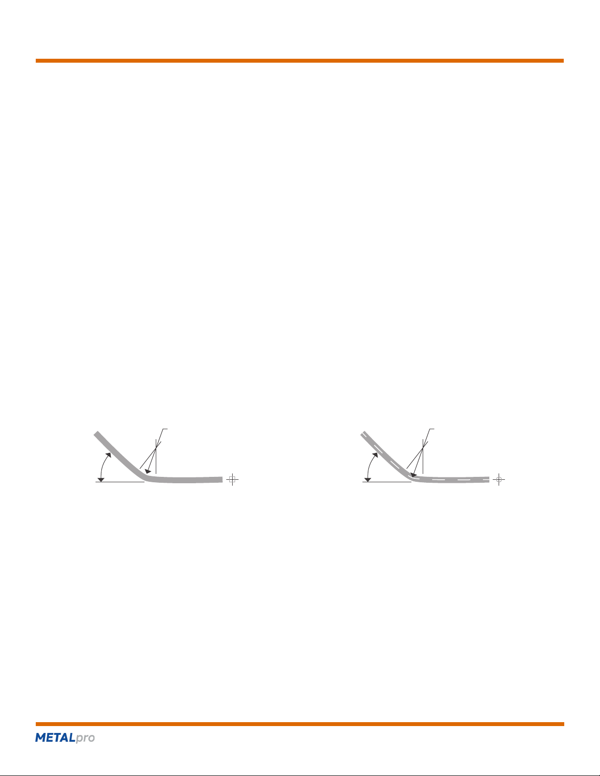
BEND RADIUS – Refer to Figures 12, 13
The MP9500 Bender can be used to bend from " to 2" square tubing, " to 2" round tubing and " to 1 " pipe.
Pages 19 & 20 indicate the minimum and maximum wall thicknesses that can be consistently and accurately formed.
The size of the rotating die determines the bend radius of the tubing. With square tubing, the bend radius is the "inside" radius of the
bent tube. With round tubing or pipe, the bend radius is the "centerline" of the tube or pipe.
NOTE: BECAUSE ALL TUBING WILL EXHIBIT SOME AMOUNT OF "SPRINGBACK", THE FINISHED BEND RADIUS MAY BE
SLIGHTLY LARGER THAN THE ROTATING DIE SIZE.
(262) 679-0504 metalprocorp.com
FIGURE 12
bend radius bend radius
degree
of bend
degree
of bend
square tubing pipe and round tubing
FIGURE 13

MP9500 Bender
page 17
More metal fabrication for your money
DEGREE OF BEND – Refer to Figures 5, 8, 9, 12, 13
The MP9500 Bender can bend tubing up to 180 degrees. Each step on the sunbursts can yield at least 45 degrees of bend. Therefore,
to bend the tubing 180 degrees, 4 strokes of the cylinder are required.
A bending gauge (66) is magnetically axed to the cylinder. The gauge is calibrated to measure the degrees of rotation of the sunbursts
in each of the 4 strokes of the cylinder. Setting the gauge to zero relative to the tube gauge (11) at the absolute start of the bend
ensures the best accuracy.
NOTE: BECAUSE OF 'SPRINGBACK' THE TUBING MAY NEED TO BE BENT PAST THE DEGREE OF BEND REQUIRED. SOME
TUBING MAY SPRINGBACK UP TO 10 DEGREES AND REQUIRE AN EQUAL AMOUNT OF OVER BENDING.
When doing multiple tubes with the same bend, an initial sample should be made and veried as accurate while noting the necessary
bend angle on the magnetic gauge allowing for spring back. Bending repeatability is then accomplished.
FEED CAGE – Refer to Figures 9, 10
The MP9500 Bender is equipped with an adjustable 'feed cage.' The purpose of the feed cage is to support the tubing as it is drawn
through the bender head to ensure that the degree of bend remains accurate and consistent. Additionally, the feed cage absorbs the
downward pressure of the tubing created by the bending process. This pressure can be detrimental to the stationary die (91), the 1/2"
x 3-5/8" pins (13) and the side plates (2). Additionally, the tubing itself can be scraped and damaged by the stationary die which has a
hardened surface.
WARNING: BENDING LARGE OR HEAVY PIPE OR TUBING WITHOUT USING OR PROPERLY ADJUSTING THE FEED CAGE WILL
RESULT IN DAMAGE TO THE MP9500 TUBING BENDER.
The feed cage is adjusted properly when the top of the rollers are the same height as the bottom of the tubing groove in the stationary
die as shown.
NOTE: THE -11 X 7 " THREADED RODS (99) ARE USED TO SUPPORT THE FEED CAGE WHEN EITHER THE 5" OR 6"
RADIUS DIES ARE USED. THE -11 X 4" THREADED RODS (100) ARE USED WITH THE 3" OR 4" RADIUS DIES. ONLY THE
TWO -11 HEX NUTS (102) ON TOP OF THE BENDER ARE USED WHEN ADJUSTING THE FEED CAGE FOR USE WITH
3" RADIUS DIES.
(262) 679-0504 metalprocorp.com

MP9500 Bender
page 18
More metal fabrication for your money
BENDING 2" PIPE – Refer to Figure 14
The 2” pipe die does not use the “Feed Cage” to support the tube. Instead, a " steel support plate laid directly on bottom plate (#9)
supports the pipe. Refer to the drawing below for proper positioning.
(262) 679-0504 metalprocorp.com
FIGURE 14
bottom plate (9)2" pipe support plate
angle iron
handle stop
Table of contents


