Metasys AFL-R User manual

Fire Management Accessories Manual 445
Miscellaneous Section
Technical Bulletin
Issue Date 0399
© 1999 Johnson Controls, Inc. 1
Code No. LIT-445220 www.johnsoncontrols.com
Preliminary—This information may change.
General Description Page 3
Installation 5
•CAB-3 Mounting 5
•ABS-8R Mounting 7
•Fiber Optic Link 8
Applications 9
•Adjusting the Audio Gain Level 10
•Notes 10
Troubleshooting 15
AFL-R and AFL-T Audio Fiber Link

Preliminary—This information may change.
2 Miscellaneous—AFL-R and AFL-T Audio Fiber Link

Preliminary—This information may change.
Miscellaneous—AFL-R and AFL-T Audio Fiber Link 3
General Description
The Audio Fiber Link (consisting of an AFL-T, AFL-R, and fiber optic
cable) distributes low-level audio signals via fiber optic media.
The AFL-T accepts low-level audio signals from the AMG-1, AMG-E, or
ATG-2. The AFL-T then converts the low-level audio signal to modulated
light, which is transmitted through multimode fiber optic cable. The
AFL-R accepts that modulated light on the other end of the fiber optic
cable. The AFL-R then converts the modulated light to low-level audio
which, in turn, feeds AA-30, AA-100, or AA-120 amplifiers and
(if required) the next daisy-chained AFL-T.
Both AFL-T and AFL-R are powered from nonresettable 24 VDC output
of power supplies such as the MPS-24A/AE, MPS-24B/BE, MPS-400,
APS-6R, or FCPS-24 which are Underwriters Laboratories (UL) Listed for
fire protective signaling service.
+
+
+
+
AudioOut-6
AudioOut+5
SignalGround4
NotUsed3
+DC/ACHi2
Ground1
Fiber
Level/Loss
+
+
+
+
AudioIn+6
SignalGround5
AudioIn-4
+DC/ACHi3
NotUsed2
Ground1
Fiber
Level/Loss
ST Male Connector ST Male Connector
AFL-R
(Receiver)
AFL-T
(Transmitter)
aflpanel
Low-Level
Audio Output -
Low-Level
Audio Output +
Low-Level
Audio Output +
Common Common
+24 VDC+24 VDC Low-Level
Audio Output -
(Output)
(Input)
Figure 1: AFL-R and AFL-T Assemblies

Preliminary—This information may change.
4 Miscellaneous—AFL-R and AFL-T Audio Fiber Link

Preliminary—This information may change.
Miscellaneous—AFL-R and AFL-T Audio Fiber Link 5
Installation
The AFL-T or AFL-R may be mounted in the Listed CHS-4, CHS-4L,
mounting chassis, or an ABS-8R enclosure (backbox). When mounting on
a CHS-4L, use the inner position. When the AFL-T or AFL-R is mounted
on the CHS-4 and CHS-4L, adequate clearance above the board is
required. Outer position mounting on the CHS-4 is possible only if the
board is mounted with components facing inward.
Use the following instructions for CAB-3 cabinet mounting.
Inner Position
Complete the following steps to mount the AFL-T or AFL-R to the
CHS-4:
1. Screw two 6-32 standoffs onto PEM studs in chassis.
2. Screw two 4-40 screws into top holes of board and attach two 4-40
standoffs.
3. Place tab on bottom of board into slot.
4. Screw boards into 6-32 standoffs with two 6-32 screws (refer to
Figure 2). The top standoffs should rest on the back of the chassis.
4-40 Screws
6-32 Standoffs
6-32 Standoffs
aflchs4
Figure 2: Mounting the AFL-T or AFL-R to the CHS-4
CAB-3
Mounting
CHS-4

Preliminary—This information may change.
6 Miscellaneous—AFL-R and AFL-T Audio Fiber Link
Outer Position
IMPORTANT: The board components must face inward.
1. Slip the board tab in the top slot of the CHS-4, with the components
facing the back of the chassis.
2. Rest the top of the board on the mounting tabs at the top of the CHS-4
and attach using two 4-40 screws.
Use the following instructions to mount the AFL-T or AFL-R to the
CHS-4L.
1. Screw the two 4-40 standoffs on the top row of PEM studs on the
CHS-4L.
2. Slide the board tab in the inner slot of the CHS-4L and rest on the
standoffs.
3. Use the two 4-40 screws to attach the board to the chassis (refer to
Figure 3).
PEM Studs
aflchs4_b
4-40 Screws
Figure 3: Mounting the AFL-T or AFL-R to the CHS-4L
CHS-4L

Preliminary—This information may change.
Miscellaneous—AFL-R and AFL-T Audio Fiber Link 7
Complete the following steps to mount the ABS-6R.
1. Determine which knockouts are required to wire the AFL-T or AFL-R
and remove the designated knockout.
2. Mount the ABS-8R.
3. Place the AFL-T or AFL-R on the PEM standoffs in the ABS-8R
four 4-40 screws (refer to Figure 4).
4. Draw appropriate wiring and fiber cable in through knockouts.
afl_abs8r
4-40 Screws
4-40 Screws
Knockouts
PEM Standoff
PEM Standoff
Knockout
Knockout
Figure 4: Mounting the AFL-T or AFL-R to the ABS-8R
ABS-8R
Mounting

Preliminary—This information may change.
8 Miscellaneous—AFL-R and AFL-T Audio Fiber Link
Figure 5 illustrates the Audio Fiber Optic Link. The attenuation of fiber
optic cabling between the AFL-T or AFL-R must not exceed a 10 dB
limit. At the system design stage, apply the following steps to establish the
limit:
1. Find the maximum dB loss per foot within the cable manufacturer’s
specifications. Determine the total attenuation between the
two nodes/repeaters due to cable.
Loss = (loss/feet) x (length in feet)
2. Establish the dB loss for each connector and splice. Sum all the losses.
3. Add the attenuation factors obtained in Steps 1 and 2 for the total.
This will provide an approximate attenuation total.
The actual attenuation can be measured end-to-end with standard fiber
optic test equipment using a signal wavelength of 850 nanometers.
The following are supported by Audio Fiber Link:
•Connectors are ST® Style
•Fiber Type Mutimode: core size is 62.5/125 micrometers.
•Wavelength is 850 nanometers.
•Maximum attenuation of fiber optic link between AFL-T and AFL-R
cannot exceed 10 dB.
Fiber Optic
Link

Preliminary—This information may change.
Miscellaneous—AFL-R and AFL-T Audio Fiber Link 9
Applications
Audio Fiber Link may be used in systems where:
•the use of wire media is not possible due to security requirements.
•fiber optic cable is already installed and available for low-level audio
distribution.
•significant distances between AMG-1 and remote amplifier cabinets
dictate the use of fiber.
•high-intensity electromagnetic fields of audible frequencies could be
coupled to wire type low-level audio circuit.
•both distance and physical location of remote cabinets require the use
of start topology.
Up to 50 AFL-T transmitters may be connected to the output of an
AMG-1, AMG-E, or ATG-2 low-level audio source.
A maximum of ten amplifiers may be fed from the AFL-R output and a
maximum of ten AFL-Ts may be fed by single AFL-R. The maximum
series connection of Audio Fiber Links is two AFL-T/R pairs deep, as
shown in Figure 5.

Preliminary—This information may change.
10 Miscellaneous—AFL-R and AFL-T Audio Fiber Link
Once the audio system installation is complete, the audio gain level must
be adjusted as follows:
1. Start with the AFL-T connected directly to the low-level audio source
(AMG-1, ATG-2). Observe the AFL-T Level Light-Emitting Diode
(LED). If the Level LED is red or flashes red continuously while
transmitting a tone/message, it is indicating a signal level that is too
high.
2. Connect one or more 470 ohm resistors in parallel across the audio
input (Terminals 4 and 6). (One 470 ohm resistor is normally installed
on the low-level audio circuit). The AFL-T Level LED indicates green
at all times except during signal switching, when it may momentarily
flash red.
3. Adjust the gain on all amplifiers that are connected in parallel on the
low-level audio circuit with the first AFL-T.
4. Proceed to the AFL-R terminating the first stage fiber optic link. If the
AFL-R feeds a second stage AFL-T, observe the Level LED. Add
one or two 470 ohm resistors in parallel with the AFL-R output if
necessary to lower the signal level.
5. Adjust the gain on all amplifiers fed from the first stage AFL-R.
6. Repeat Step 4 for all the amplifiers fed from the second stage AFL-R.
Add parallel resistors if necessary.
7. Test the entire system in Systems Normal and Alarm (tone/message
being generated by the AMG or ATG)—checking each signal that will
be used—to verify that the above requirements are satisfied and that
there is no significant audible distortion.
The following notes provide additional installation guidelines:
•A system requiring many fiber links may also require larger batteries
and external chargers. The AFL-T and AFL-R have operating currents
of 104 mA and 51 mA (respectively) and operate from 20.4 to
26.4 VDC. Refer to fire panel instructions for calculations.
•AFL-T must be powered by the 24 VDC UL Listed power supply
connected to the same reference (battery negative) as the audio signal
source (AMG, ATG, and AFL-R).
•Class A low-level audio looped riser cannot be implemented when
using Audio Fiber Link.
•Any combination of up to 50 AFL-T transmitters and AA-30, AA-100,
and AA-120 series amplifiers may be connected to the output of any
one AMG or ATG. All of the AFL-T transmitters must remain in the
same cabinet as the AMG or ATG.
Adjusting the
Audio Gain
Level
Notes

Preliminary—This information may change.
Miscellaneous—AFL-R and AFL-T Audio Fiber Link 11
12 9 8 7 6 5 4 3 2 111 10
12 9 8 7 6 5 4 3 2 111 10
Main Control Panel Cabinet
MPS-24A or
MPS-24AE
Remote Amplifier Cabinet Remote Amplifier Cabinet
AA-30/AA-30E
8 7 6 5 4 3 2 1
AA-30/AA-30E
8 7 6 5 4 3 2 1
ATG-2
8 7 6 5 4 3 2 1 6 5 4 3 2 1
Low-level
Alert Riser
P4
P4
P3 P8
Low-level
Audio Riser
+
+
+
+
Fiber
Optic
Cable
Fiber
Optic
Cable
Fiber
Optic
Cable
AFL-R
MPS-24A or
MPS-24AE
AA-30/AA-30E
8 7 6 5 4 3 2 1
P3
P3
P3
+
+
+
+
AFL-T
+
+
+
+
AFL-T
MPS-24A or
MPS-24AE
P3
P3
P4
+
+
+
+
AFL-T
6 5 4 3 2 1
+
+
+
+
AFL-T
AA-30/AA-30E
8 7 6 5 4 3 2 1
To AFL-R in
a Remote
Amplifier
Cabinet
Origin of
Main Audio Riser
afl_3cabinets
12 1110 9 8 7 6 5 4 3 2 1
Figure 5: Audio Fiber Optic Link

Preliminary—This information may change.
12 Miscellaneous—AFL-R and AFL-T Audio Fiber Link
+
+
+
+
AudioIn+6
5
4
3
2
Ground1
SignalGround
AudioIn-
+DC/ACHi
NotUsed
Fiber
Status
+
+
+
+
AudioIn+6
5
4
3
2
Ground1
SignalGround
AudioIn-
+DC/ACHi
NotUsed
Fiber
Status
Fiber to
AFL-R
AFL-T
Fiber to
AFL-R
AFL-T
aflwire1
6 5 4 3 2 1
+ -+ -
To 24V Non-resettable
UL Listed Power Supply Output
Connected to the Same Reference
(Battery Negative) as the Audio
Source (AMG-1, AMG-E)
Up to a Total of
50 AFL-Ts or Amplifiers
Optional Return
Low-level Audio
R-470
470 ohm
Resistor
P4
+
-+
-
AMG-1
AMG-E
s
Figure 6: Connecting the AFL-T to the AMG-1/AMG-E

Preliminary—This information may change.
Miscellaneous—AFL-R and AFL-T Audio Fiber Link 13
+
+
+
+
AudioIn+6
5
4
3
2
Ground1
SignalGround
AudioIn-
+DC/ACHi
NotUsed
Fiber
Status
aflwire2
+
+
+
+
AudioIn+6
5
4
3
2
Ground1
SignalGround
AudioIn-
+DC/ACHi
NotUsed
Fiber
Status
6 5 4 3 2 1
+ -+ -
Fiber to
AFL-R
AFL-T
Up to a Total
of 50 AFL-Ts
or Amplifiers
Up to a Total
of 50 AFL-Ts
or Amplifiers
Low-level
Audio EVAC
Low-level
Audio Alert
Fiber to
AFL-R
R-470
470 ohms
Resistors
AFL-T
P8
ATG-2
+
-+
-
To 24V Non-resettable
UL Listed Power Supply
Output Connected to the
Same Reference
(Battery Negative)
as the Audio
Source (ATG-2)
Figure 7: Connecting AFL-Ts to the ATG-2
Preliminary—This information may change.
14 Miscellaneous—AFL-R and AFL-T Audio Fiber Link
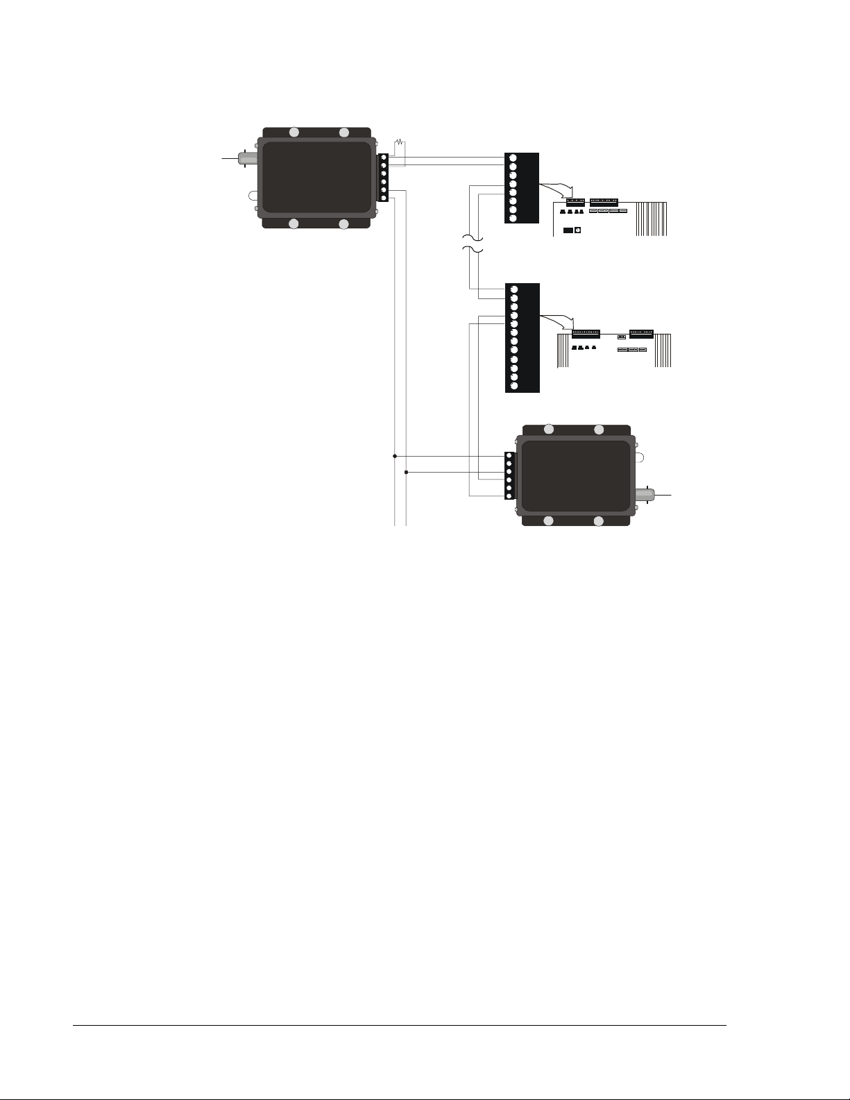
+
+
+
+
AudioOut-6
5
4
3
2
Ground1
AudioOut+
SignalGround
NotUsed
+DC/ACHi
Fiber
Level/Loss
AFL-R
+
+
+
+
1
2
3
4-
5
6+
Ground
NotUsed
+DC/ACHi
AudioIn
SignalGround
AudioIn
Status
Fiber
AFL-T
8 7 6 5 4 3 2 1
+ -+ -
121110 9 8 7 6 5 4 3 2 1
+ -+ -
AA30
P3
P3
Second
Stage Fiber
Optic Link
AA-100/AA-120
Fiber from
the First
Stage AFL-T
To 24V Non-resettable UL Listed
Power Supply Output Connected
to the Same Reference as the
Audio Source
Up to a
Total of 10
Amplifiers/
AFL-Ts
R-470
470 ohms
Resistor
+
-
Second Stage AFL-T
aflwire3
In this figure, AFL-R is the audio source
Figure 8: Connecting the AFL-R to Amplifiers and Second
Stage AFL-Ts

Preliminary—This information may change.
Miscellaneous—AFL-R and AFL-T Audio Fiber Link 15
Troubleshooting
The AFL-T Light-Emitting Diode (LED) displays various intensities of
green depending on the signal level. Abnormally high levels of audio
signal will cause the LED to glow steady red, indicating distortion.
The AFL-R LED displays various intensities of green depending on
optical power delivered (the lower the optical signal level, the dimmer the
intensity of the LED). The AFL-R LED will glow steady red if the link is
not receiving enough light or if the fiber is disconnected.
It is normal for bi-color LEDs on both units to momentarily change from
green to red during paging and message operation.

Preliminary—This information may change.
16 Miscellaneous—AFL-R and AFL-T Audio Fiber Link
Notes
Controls Group www.johnsoncontrols.com
507 E. Michigan Street FAN 445
P.O. Box 423 Fire Management Accessories Manual
Milwaukee, WI 53201 Printed in U.S.A.
This manual suits for next models
1
Table of contents


