Ross MUX-8552A User manual

Ross Video Limited
MUX-8552A(-C)
AES/EBU Embedder/Multiplexer
User Manual
Ross Part Number: 8552ADR-004
Issue: 01

MUX-8552A •AES/EBU Embedder/Multiplexer User Manual
•Ross Part Number: 8552ADR-004
•Document Issue: 01
•Printed in Canada.
The information contained in this User Manual is subject to change without notice or obligation.
Copyright
© 2007 Ross Video Limited. All rights reserved.
Contents of this publication may not be reproduced in any form without the written permission of Ross
Video Limited. Reproduction or reverse engineering of copyrighted software is prohibited.
Notice
The material in this manual is furnished for informational use only. It is subject to change without
notice and should not be construed as a commitment by Ross Video Limited. Ross Video Limited
assumes no responsibility or liability for errors or inaccuracies that may appear in this manual.
Trademarks
•is a registered trademark of Ross Video Limited.
•Ross, ROSS, ROSS®, and MLE are registered trademarks of Ross Video Limited.
•All other product names and any registered and unregistered trademarks mentioned in
this manual are used for identification purposes only and remain the exclusive property
of their respective owners.

Important Regulatory and Safety Notices
Before using this product and any associated equipment, refer to the “Important Safety Instructions”
listed below so as to avoid personnel injury and to prevent product damage.
Products may require specific equipment, and /or installation procedures be carried out to satisfy
certain regulatory compliance requirements. Notices have been included in this publication to call
attention to these Specific requirements.
Symbol Meanings
This symbol on the equipment refers you to important operating and maintenance
(servicing) instructions within the Product Manual Documentation. Failure to heed
this information may present a major risk of damage or injury to persons or
equipment.
Warning
The symbol with the word “Warning” within the equipment manual indicates a
potentially hazardous situation, which if not avoided, could result in death or serious
injury.
Caution
The symbol with the word “Caution” within the equipment manual indicates a
potentially hazardous situation, which if not avoided, may result in minor or
moderate injury. It may also be used to alert against unsafe practices.
Notice
The symbol with the word “Notice” within the equipment manual indicates a
situation, which if not avoided, may result in major or minor equipment damage or a
situation which could place the equipment in a non-compliant operating state.
ESD
Susceptibility
This symbol is used to alert the user that an electrical or electronic device or
assembly is susceptible to damage from an ESD event.
Important Safety Instructions
Caution
This product is intended to be a component product of the RossGear 8000A series
frame. Refer to the RossGear 8000A series frame User Manual for important safety
instructions regarding the proper installation and safe operation of the frame as well
as it’s component products.
Warning
Certain parts of this equipment namely the power supply area still present a safety
hazard, with the power switch in the OFF position. To avoid electrical shock,
disconnect all A/C power cords from the chassis' rear appliance connectors before
servicing this area.
Warning
Service barriers within this product are intended to protect the operator and service
personnel from hazardous voltages. For continued safety, replace all barriers after
any servicing.
This product contains safety critical parts, which if incorrectly replaced may present
a risk of fire or electrical shock. Components contained within the product’s power
supplies and power supply area, are not intended to be customer serviced and should
be returned to the factory for repair.
To reduce the risk of fire, replacement fuses must be the same type and rating.
Only use attachments/accessories specified by the manufacturer.

EMC Notices
US FCC Part 15
This equipment has been tested and found to comply with the limits for a class A Digital device,
pursuant to part 15 of the FCC Rules. These limits are designed to provide reasonable protection
against harmful interference when the equipment is operated in a commercial environment. This
equipment generates, uses, and can radiate radio frequency energy and, if not installed and used in
accordance with the instruction manual, may cause harmful interference to radio communications.
Operation of this equipment in a residential area is likely to cause harmful interference in which case
users will be required to correct the interference at their own expense.
Notice
Changes or modifications to this equipment not expressly approved by Ross Video
Ltd. could void the user’s authority to operate this equipment.
CANADA
This Class “A” digital apparatus complies with Canadian ICES-003.
Cet appareil numerique de classe “A” est conforme à la norme NMB-003 du Canada.
EUROPE
This equipment is in compliance with the essential requirements and other relevant provisions of CE
Directive 93/68/EEC.
INTERNATIONAL
This equipment has been tested to CISPR 22:1997 along with amendments A1:2000 and A2:2002 and
found to comply with the limits for a Class A Digital device.
Notice
This is a Class A product. In domestic environments this product may cause radio
interference in which case the user may have to take adequate measures.
Maintenance/User Serviceable Parts
Routine maintenance to this RossGear product is not required. This product contains no user
serviceable parts. If the module does not appear to be working properly, please contact Technical
Support using the numbers listed under the “Contact Us” section on the last page of this manual. All
RossGear products are covered by a generous 5-year warranty and will be repaired without charge for
materials or labor within this period. Refer to the section, “Warranty and Repair Policy” in this
manual for details.

Environmental Information
The equipment that you purchased required the extraction and use of natural resources for its
production. It may contain hazardous substances that could impact health and the environment.
To avoid the potential release of those substances into the environment and to diminish the need for
the extraction of natural resources, Ross Video encourages you to use the appropriate take-back
systems. These systems will reuse or recycle most of the materials from your end-of-life equipment in
an environmentally friendly and health conscious manner.
The crossed-out wheeled bin symbol invites you to use these systems.
If you need more information on the collection, reuse, and recycling systems, please contact your local
or regional waste administration.
You can also contact Ross Video for more information on the environmental performances of our
products.


MUX-8552A User Manual (Iss. 01) Contents •i
Contents
Introduction 1-1
In This Chapter .......................................................................................................................1-1
A Word of Thanks....................................................................................................1-1
MUX-8552A Overview............................................................................................1-2
MUX-8552A-C Overview........................................................................................1-2
Features ....................................................................................................................1-3
Functional Block Diagram .......................................................................................1-4
Documentation Terms ..............................................................................................1-4
Installation and Setup 2-1
In This Chapter .......................................................................................................................2-1
Static Discharge........................................................................................................2-1
Unpacking ................................................................................................................2-1
Board Installation .....................................................................................................2-2
BNC Labels ..............................................................................................................2-2
MUX-8552A Cable Connections .............................................................................2-2
MUX-8552A-C Cable Connections .........................................................................2-3
User Controls 3-1
In This Chapter .......................................................................................................................3-1
MUX-8552A Jumper Locations...............................................................................3-2
MUX-8552A-C Jumper Locations...........................................................................3-3
MUX-8552A-C Gain Adjustment............................................................................3-4
LEDs.........................................................................................................................3-4
SMPTE 269M Fault Reporting 4-1
In This Chapter .......................................................................................................................4-1
Overview ..................................................................................................................4-1
Jumper Setup ............................................................................................................4-2
Frame Connections...................................................................................................4-2
Details.......................................................................................................................4-2
Specifications 5-1
In This Chapter .......................................................................................................................5-1
MUX-8552A Technical Specifications ....................................................................5-2
AAM-8552A Technical Specifications ....................................................................5-3
Channel Status Data Table for Analog Mode...........................................................5-4
Channel Status Data for AES Mode.........................................................................5-4

ii •Contents MUX-8552A User Manual (Iss. 01)
Service Information 6-1
In This Chapter ...................................................................................................................... 6-1
Troubleshooting Checklist....................................................................................... 6-1
Warranty and Repair Policy .................................................................................... 6-2
Ordering Information 7-1
In This Chapter ...................................................................................................................... 7-1
MUX-8552A and Related Products......................................................................... 7-1

MUX-8552A User Manual (Iss. 01) Introduction •1-1
Introduction
In This Chapter
This chapter contains the following sections:
• A Word of Thanks
• MUX-8552A Overview
• MUX-8552A-C Overview
• Features
• Functional Block Diagram
• Documentation Terms
A Word of Thanks
Congratulations on purchasing the Ross Video MUX-8552A,AES/EBU Embedder/Multiplexer.
The MUX-8552A family is part of a full line of RossGear Digital products, backed by Ross Video’s
experience in engineering and design expertise since 1974.
You will be pleased at how easily your new MUX-8552A fits into your overall working environment.
Equally pleasing is the product quality, reliability, and functionality. Thank you for joining the ever-
growing group of worldwide satisfied Ross Video customers!
We recommend that you read the sections in this User Manual that are relevant to your particular
card(s) before installation. In this way you will ensure its proper integration into your facility and
maximize the features and functionality of the card.
This manual provides installation and operational instructions for both the MUX-8552A and the
MUX-8552A-C versions. Should you have a question pertaining to the operation of your MUX-
8552A or MUX-8552A-C, please contact us at the numbers listed on the back cover of this
publication. Our technical support staff is always available for consultation, training, or service.

1-2 •Introduction MUX-8552A User Manual (Iss. 01)
MUX-8552A Overview
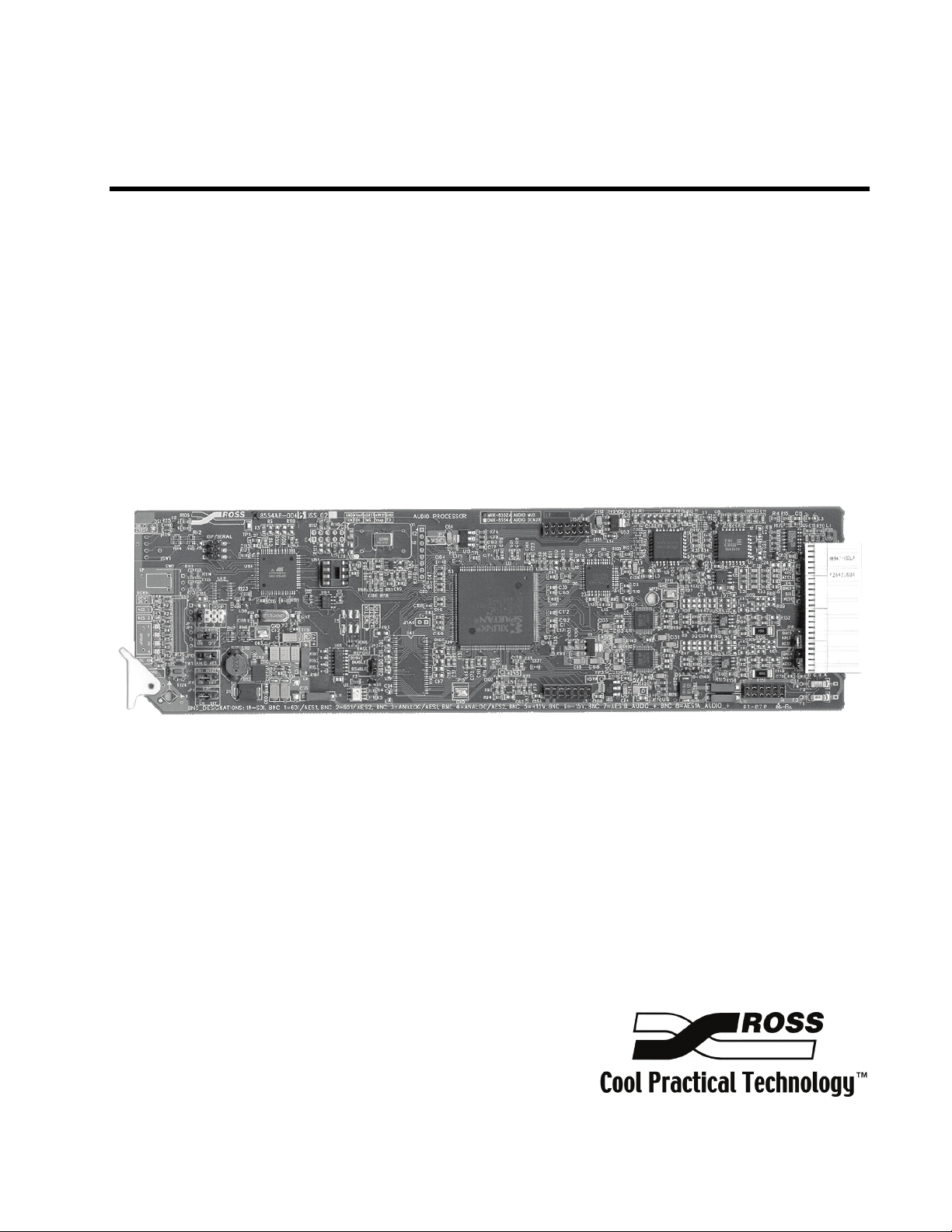
The RossGear MUX-8552A AES/EBU Embedder/Multiplexer is a broadcast quality modular product
used to write 20-bit AES audio streams (SMPTE 272M-A) to a 525 or 625 standard 270MB/s SDI
video signal. The MUX-8552A will embed two 48kHz AES-3id streams (1 group) and output two
copies of the embedded SDI signal. The RossGear MUX-8552A is for use in 75-ohm coaxial SMPTE
276M and AES-3id systems.
An SDI signal and 1 or 2 AES-3id signals are input through BNC connectors on the rear of the frame.
The MUX-8552A accepts both 525 and 625 format (SMPTE 259M-C) signals at 270Mb/s. Visual
indicators on the card edge provide indication of the presence of SDI and AES inputs. The MUX-
8552A provides automatic equalization for 300m of Belden 8281 cable. Two SDI outputs are
provided.
The MUX-8552A can embed one AES group into any one of the four AES groups available. The
group to be embedded is selected via a card edge jumper. Front panel LED’s provide information on
which groups are already present in the incoming SDI stream. The ability to overwrite an incoming
group is available through jumper selection. The MUX-8552A has been designed with the ability to
report a variety of AES signal errors including: no lock, biphase coding, parity, CRC check, sample
slip, and validity errors. These errors are indicated on a card edge (Error) LED. In addition, there is
SMPTE 269M fault reporting output to the backplane of the Ross digital rack frame.
The MUX-8552A is also available as the MUX-8552A-C version. The C version comes pre-
assembled from the factory with the AAM-8552A A/D daughter card, and the CON-8552 companion
rear connector module, which provides four balanced analog audio inputs instead of the AES digital
audio inputs.
The MUX-8552A fits into the Ross DFR-8110A or DFR-8104A digital frames. It provides system
builders the ability to easily distribute embedded digital audio in an SDI facility. The MUX-8552A is
part of a growing line of RossGear AES solutions, including distribution, conversion and monitoring.
The MUX-8552A also fits Leitch*6800 series frames.
Designed and manufactured to meet the highest quality broadcast industry standards, the RossGear
MUX-8552A is an ideal, cost effective solution for digital audio embedding.
MUX-8552A-C Overview
The RossGear MUX-8552A-C version, which comprises the MUX-8552A, the AAM-8552A
(daughter card), and the companion CON-8552 (connector adapter), is a broadcast quality modular
product used to allow four analog audio inputs to be embedded into a 525 or 625 SDI stream. The
AAM-8552A is a sub-module daughter card that plugs onto the top of the MUX-8552A RossGear
AES multiplexer card. The CON-8552 is a plug-on connector to the BNC module that connects to the
rear of the Ross DFR-8110A or DFR-8104A digital frame.
The AAM-8552A uses state of the art analog to digital converters that provide 24-bit resolution. A
coarse level adjustment (headroom) jumper (18dB or 24dB) and fine adjustment potentiometers (+/-
3dB, one for each channel) on the AAM-8552A, are provided to precisely match the converter to your
facility’s house reference audio level.
The AAM-8552A / CON-8552 is part of a growing line of RossGear AES solutions, including
distribution, conversion and monitoring. Designed and manufactured to meet the highest quality
broadcast industry standards, the RossGear MUX-8552A / AAM-8552A / CON-8552 is an ideal, cost
effective solution for digital and analog audio multiplexing requirements in your facility.
*Leitch is a trademark of Leitch Technology Corporation

MUX-8552A User Manual (Iss. 01) Introduction •1-3
Features
The MUX-8552A AES/EBU Embedder/Multiplexer is part of a full line of RossGear digital and
analog distribution products engineered to satisfy the highest quality broadcast standards and the most
demanding requirements of your facility. The following features make the MUX-8552A the most
versatile AES/EBU Embedder/Multiplexer card for your professional audio-video requirements:
MUX-8552A Features
• Compliance with SMPTE 272M-A 48kHz 20-bit
• Automatic 525/625 format detection
• AES synchronization
• AES sample rate conversion
• Jumper selectable EDH insertion
• Auto cable equalization for 300m of Belden 8281
• Visual indication of signal presence
• Visual indication of an error condition
• Visual indication of AES groups present
• SMPTE fault reporting in accordance with SMPTE 269M
• Conformity to AES-3id 1995
• Two SDI video outputs
• 5-year warranty
• Compatible with Ross 8100 series and Leitch 6800 series frames
MUX-8552A-C Features
• AAM-8552A daughter card
o Compliance with SMPTE 272M-A 48kHz 20-bit AES/EBU audio
o 24-bit ADC resolution
o Selectable maximum input level from +15dBu to +27dBu
o +0.05 dB frequency response 20 Hz to 22 kHz
o 5-year warranty
• CON-8552 analog audio input adaptor
o 2 balanced analog stereo input channels
o 5-year warranty
o Compatible with Ross DFR-8110A-C and DFR-8104A-C frames

1-4 •Introduction MUX-8552A User Manual (Iss. 01)
Functional Block Diagram
Figure 1. Simplified Block Diagram of MUX-8552A(-C)
Documentation Terms
The following terms are used throughout this guide:
• “Frame” refers to the DFR-8104A and DFR-8110A frames that house the MUX-
8552A card.
• All references to the DFR-8104A and DFR-8110A also include the
DFR-8104A-C and DFR-8110A-C versions with the cooling fan option. See the
respective User Manuals for details.
• “Operator” and “User” both refer to the person who uses the MUX-8552A.
• “Board”, “Card”, and “Module” all refer to the MUX-8552A board itself,
including all components and switches.
• “System” and “Video system” refer to the mix of interconnected production and
terminal equipment in which the MUX-8552A operates.
• “525-line mode” refers to broadcast situations using NTSC composite (analog)
signal reference inputs.
• “625-line mode” refers to broadcast situations using PAL-B composite (analog)
signal reference inputs. All references to PAL in this manual imply that PAL-B is
being used.

MUX-8552A User Manual (Iss. 01) Installation and Setup •2-1
Installation and Setup
In This Chapter
This chapter contains the following sections:
• Static Discharge
• Unpacking
• Board Installation
• BNC Labels
• MUX-8552A Cable Connections
• MUX-8552A-C Cable Connections
Static Discharge
Whenever handling the MUX-8552A and other related equipment, please observe all static discharge
precautions as described in the following note:
ESD
Susceptibility
Static discharge can cause serious damage to sensitive
semiconductor devices. Avoid handling circuit boards in high
static environments such as carpeted areas, and when wearing
synthetic fiber clothing. Always exercise proper grounding
precautions when working on circuit boards and related
equipment.
Unpacking
Unpack each MUX-8552A from the shipping container and check the contents to ensure that all items
are included. If any items are missing or damaged, contact your sales representative or Ross Video
directly.

2-2 •Installation and Setup MUX-8552A User Manual (Iss. 01)
Board Installation
Note the following points when installing the configured MUX-8552A card in a RossGear 8000 or
8000A series digital distribution frame:
Notice
The MUX-8552A-C card configuration must be installed in a
Ross Video 8000A series digital distribution frame with a
cooling module option installed.
• Refer to the User Manual of the RossGear 8000 or 8000A series frame, to ensure
that the frame is properly installed according to instructions. If this module is to be
installed in any compatible frame other than a Ross Video product, refer to the
manual that came with your frame, for specific instructions.
• Please note that heat and power distribution requirements within a frame may dictate
specific slot placement of cards. Cards with many heat-producing components
should be arranged to avoid areas of excess heat build-up, particularly in frames
using convection cooling.
• After selecting the desired frame installation slot, hold the MUX-8552A card by the
edges and carefully align the card edges with the slots in the frame. Then fully insert
the card into the frame until the rear connection plug is properly seated.
BNC Labels
Affix the supplied BNC label, as per the included instructions, to the BNC area on the rear of the rack
frame.
MUX-8552A Cable Connections
The following section provides instructions for cable connections when mounting the MUX-8552A in
a RossGear 8000 or 8000A series Digital Distribution Frame. If this card is installed in a compatible
distribution frame other than a Ross frame, note that the cable designations may vary.
Use the diagram below to attach the required BNC cables such as the SDI input and output, AES input
and output streams.
Figure 2. MUX-8552A BNC Designations for RossGear DFR-8110A (2RU frame)

MUX-8552A User Manual (Iss. 01) Installation and Setup •2-3
AES Input
The MUX-8552A can accommodate two synchronous AES-3id input streams at 48 kHz or any
asynchronous AES stream from 20kHz to 103kHz with sample rate conversion (SRC) enabled. SRC
should only be used with PCM (Pulse Code mOdulate) digiatal audio and not any form of conpression
ie. Dolby.
MUX-8552A-C Cable Connections
The following section provides instructions for cable connections when mounting the MUX-8552A-C
in a RossGear 8000 or 8000A series Digital Distribution Frame.
Use the diagram below for guidelines to:
• install the CON-8552 rear audio sub module onto the back of the Ross digital rack
frame.
• attach the required SDI input and output BNC cables.
Figure 3. MUX-8552A-C BNC Designations for RossGear DFR-8110A (2RU frame)

2-4 •Installation and Setup MUX-8552A User Manual (Iss. 01)
Analog Cables
On the CON-8552 adapter, there are removable connectors for sockets Analog Audio IN- 1A, 1B, 2A,
and 2B. Each connector has sockets for the positive, negative, and grounded wires of a balanced
analog audio cable.
Wire the external cables to the terminal block connectors as outlined in the diagram and procedure
below.
Figure 4. Connector Wiring for CON-8552 Input Sockets
Use the following procedure to wire the external cables to the terminal block connectors:
1. Insert an analog audio wire to the designated polarity slot on the connector.
2. Use a tweaker screwdriver to tighten the corresponding screw on the underside of
the connector.
3. Repeat steps 1 and 2 for each wire on each connector.
Once the cables have been wired to the connectors, install the connectors to the sockets on the CON-
8552 adapter so that the slotted tongue fits in the grooves on the adapter socket.

MUX-8552A User Manual (Iss. 01) User Controls •3-1
User Controls
In This Chapter
This chapter contains the following sections:
• MUX-8552A Jumper Locations
• MUX-8554A-C Jumper Locations
• MUX-8552A-C Gain Adjustment
• LEDs

3-2 •User Controls MUX-8552A User Manual (Iss. 01)
MUX-8552A Jumper Locations
Use the following information to set jumpers based on your configuration requirements.
Figure 5. MUX-8552A Jumper Locations
Analog/AES Audio – JP7, JP8, JP10
Select AES on JP7, JP8, and JP10 if the input is to be AES digital audio. The default is AES.
Group Select – JP11
Select the incoming AES group to embed: group 1, 2, 3, or 4 via JP11. The default is 1.
Overwrite – JP9
Select Overwrite ON or OFF via JP9, to allow the destructive overwrite of the selected AES group.
• ON — Overwrites the existing audio group. The default is ON.
• OFF — If there is pre-existing audio on the JP11 selected group, the card will allow that
audio to pass unaltered and will not insert audio. If there is no pre-existing audio on the JP11
selected group, the card will insert new audio.
EDH Insertion – JP6
Select the EDH Insertion, ON or OFF, via JP6. The default is ON.
SMPTE Fault Reporting – JP3
Select SMPTE 269M Fault Reporting, ENABLED or DISABLED, via JP3. The default is EN.
Refer to Chapter 3, “SMPTE 269M Fault Reporting”, in this manual, for details on fault reporting.
SRC Select – JP1
Select SRC ON or OFF, via JP1, to enable the Sample Rate conversion. Select ON to enable the
MUX-8552A to automatically synchronize and convert to 48kHz any AES input from 20kHz to
103kHz. The default is ON.

MUX-8552A User Manual (Iss. 01) User Controls •3-3
MUX-8552A-C Jumper Locations
Use the following information to set jumpers based on your configuration requirements.
Figure 6. MUX-8552A-C Jumper Locations
Analog/AES Audio – JP7, JP8, JP10
On the MUX-8552A card, select ANALOG on JP7, JP8, and JP10 if the input is to be analog audio.
Note that you must have the AAM-8552A and CON-8552 installed to input four analog audio
channels instead of two AES digital audio channels into the MUX. The default is ANALOG.
Group Select – JP11
Select the AES group to embed: group 1, 2, 3, or 4 via JP11. The default is 1.
Overwrite – JP9
Select Overwrite ON or OFF via JP9, to allow the destructive overwrite of the selected AES group.
• ON – Overwrites the existing audio group. The default is ON.
• OFF – If there is pre-existing audio on the JP11 selected group, the card will allow that
audio to pass unaltered and will not insert audio. If there is no pre-existing audio on the JP11
selected group, the card will insert new audio.
Analog Input Levels – JP1, JP2, JP3, JP4
On the AAM-8552A daughter card, select the coarse analog audio input headroom level (-18 or -
24dB) for each channel using JP1, JP2, JP3, and JP4. The default is –24dB.
EDH Insertion – JP6
On the MUX-8552A card, select the EDH Insertion, ON or OFF, via JP6. The default is ON.
SMPTE Fault Reporting – JP3
On the MUX-8552A card, select SMPTE 269M Fault Reporting, ENABLED or DISABLED, via
JP3. The default is EN. Refer to Chapter 3, “SMPTE 269M Fault Reporting” in this manual, for
details on fault reporting.

3-4 •User Controls MUX-8552A User Manual (Iss. 01)
MUX-8552A-C Gain Adjustment
If necessary, use a tweaker screwdriver to adjust the fine analog audio input levels for each channel on
the AAM-8552A. See Figure 6 for potentiometer locations. The potentiometer assignments are:
• RV4 for AES1A
• RV3 for AES1B
• RV2 for AES2A
• RV1 for AES2B
These potentiometers provide 9dB range of adjustment on the –18dBFS jumper setting and a 6dB
range of adjustment on the –24dBFS jumper setting. Using these adjustments, the total headroom is
adjustable over the –15 to –27dBFS range.
Note All fine levels are factory set for unity gain and should not need
adjusting.
An extender card is required (EXT-8100) to adjust
potentiometer settings. Refer to the section, “Optional
Equipment” in this manual, for details.
LEDs
When all jumper and cabling configuration is complete, apply the SDI video input signal. The group
LEDs will indicate which groups have embedded audio.
Figure 7. Card-edge LEDs
The front card edge has LEDs that display the status of input signals. The LED displays are described
in the preceding figure and the following table:
This manual suits for next models
1
Table of contents
Other Ross Recording Equipment manuals

Ross
Ross XPression User manual

Ross
Ross SRG-2200 User manual

Ross
Ross XPression User manual

Ross
Ross Synergy 1 SD User manual

Ross
Ross OpenGear SFS-8622 Series User manual

Ross
Ross NK Series User manual

Ross
Ross MB-650 User manual

Ross
Ross GRAPHITE-4RU-1ME-9IN User manual

Ross
Ross FSU-8032A Quick start guide

Ross
Ross RCS-8120 User manual