MetaSystem T.30-Def-Com 30 User manual

• ALL INSTALLATION OPERATIONS MUST BE CARRIED OUT WITH THE ENGINE OFF.
• Before starting installation, carefully asses the position of the device, according to the available space, to the length
of the power cables, and to the horizontal position that it needs to maintain.
• The product needs to be installed in an area that is only accessible to the service sta (Service Access Area On).
• Carefully follow the steps outlined in this manual.
• Installation sta are not authorised to remove warranty seals and/or access the inside of the product and accesso-
ries.
• The sta in charge of the installation is not authorised to alter and/or adapt the product and its relative accessories.
• The manufacturer assumes no responsibility for damages caused to property and/or people, caused by the in-
correct installation of the product.
• ATTENTION: Risk of explosion if the internal batteries are replaced with non-equivalent models, other than those
contained in the product.
INSTALLATION MANUAL
MOTORCYCLE TELEMATIC ALARM
T.30 - Def-Com 30
EN
5040342900-WEB
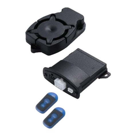
KIT COMPOSITION
WARNINGS
A
ALARM
CONTROL UNIT
B
ALARM
WIRING
E
ALARM
ACCESSORY BAG
G
DETERGENT
WIPE
D
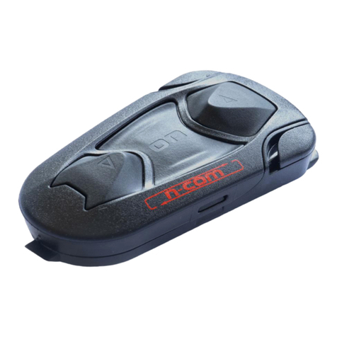
TELEMATIC
CONTROL UNIT
C
CONNECTION
HARNESS
F
TELEMATIC
ACCESSORY BAG
Power supply: ...............................................................................................................12Vdc (10V-15V)
Working temperature: ...........................................................................between -25°C and +85°C
Protection rating: .............................................................................................................................. IP 65
Application classication: .................................................................................................motorcycle
ALARM CONTROL UNIT: TECHNICAL SPECIFICATIONS
Power supply: ..............................................................................................................12Vdc (10V-24V)
Working temperature: ......................................................................... between -30°C and +80°C;
Protection rating: ............................................................................................................................. IP 65
Application classication: .................................................................................................motorcycle
TELEMATIC CONTROL UNIT: TECHNICAL SPECIFICATIONS

POSITION OF VEHICLE DURING INSTALLATION
ATTENTION: All installation operations must be carried out with the
motor vehicle parked outdoors on at ground and with the engine o.
The instructions in this manual do not refer to specic motor vehicle models but apply to all motor vehicles in general.
Any information provided by Meta System regarding a type (model) of vehicle is to be considered purely indicative.
Installation, positioning, product securing and electrical connections, and possibly the removal, must be carried out in
a workmanlike manner on each motor vehicle. The installer is obliged to and bears responsibility for carefully verifying
the individual vehicle model on which operations are carried out. Failure to comply with that stipulated above can ren-
der the warranty of the device null and void.
APPLICABLE RULES
ALARM CONTROL UNIT: WARNINGS ON DEVICE POSITIONING
2

WIRING - METAL PANELS
GPS
DIRECTIONAL
ANTENNA
ATTENTION: make sure that the telematic control unit is
at least 50 cm from the ECU (engine control unit).
ATTENTION
If horizontal installation is not possible, pro-
ceed with vertical installation.
Do not secure the telematic control unit
with the cables set up upwards!!
TELEMATIC CONTROL UNIT: WARNINGS ON DEVICE POSITIONING
TELEMATIC CONTROL UNIT: INSTALLATION
Below is some information on positioning and mounting the telematic control unit:
• Identify a at area for mounting.
• Clean the area with the supplied detergent wipe and remove the adhesive lm from the telematic control unit.
• Position and mount the telematic control unit by pressing for at least 10 seconds.
IN HORIZONTAL POSITION
3

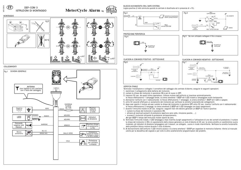
ALARM CONTROL UNIT: GENERAL DIAGRAM
ANTENNA
(do not cut and do not tape
with the rest of the wiring)
BATTERY
NEGATIVE
(-)
LED
HORN RELAY
NEGATIVE COMMAND
IGNITION
BLOCK
BATTERY
POSITIVE
(+12V)
TURN
SIGNALS
Install
15A fuse
RED
LIGHT BLUE
ORANGE
YELLOW/GREEN
PURPLE
BLUE (C)
GREY (NO)
BROWN
WHITE
BLACK
LIGHT BLUE
IGNITION KEY
POSITIVE POLE
(+15)
PROTECTION AGAINST CUT-
OFF OF EXPOSED CONDUCTIVE
PARTS (CONNECT TO CONDUCTI-
VE PARTS IF NOT USED)
PROTECTION FOR
CONTACT WITH
EXPOSED CONDUCTIVE
PARTS
ALARM CONTROL UNIT: IGNITION BLOCK (FAIL SAFE SYSTEM)
ALARM CONTROL UNIT: PERIPHERAL PROTECTION
IGNITION CONTROL UNIT,
COIL, FUEL PUMP...
DEFCOM 30
CONTROL UNIT
RELAY COIL
FROM THE
MAGNET
ADDITIONAL
RELAY
DEFCOM 30
CONTROL UNIT RELAY
IGNITION
KEY
BLOCK
IGNITION
KEY
BLOCK
BLUE
GREY BLUE
GREY
BUTTON TO
BE INSTALLED
BUTTON TO
BE INSTALLED
YELLOW/GREEN
PURPLE
4
RED
BLACK

ATTENTION: First connect the fork contact
with RED SHEATH to the POSITIVE POLE
of the battery and, subsequently, the fork
contact with BLACK SHEATH to the NEGATIVE
POLE.
Verify that the led on the device ashes; if
not, check the connections and/or contact the
after-sales service
ALARM CONTROL UNIT: ELECTRICAL CONNECTIONS (connection to the battery)
CONTROL-OPERATED HORN
POSITIVE - LOCKED
ORIGINAL
COMMAND
ADDITIONAL
RELAY
TO
ROOT
COMMANDS
IGNITION
KEY BLOCK
IGNITION
KEY BLOCK
BROWN
LIGHT BLUE
HORN HORN
ORIGINAL
COMMAND
ADDITIONAL
RELAY
BROWN
P600 DIODES
TO BE INSTALLED
TURN
SIGNALS
CONTROL-OPERATED HORN
NEGATIVE - LOCKED
5
TELEMATIC CONTROL UNIT: DIAGNOSTICS
The telematic control unit is equipped with a LED to provide diagnostic information and it is installed on top of the de-
vice. Based on the indications in the table below it is possible to verify the connectivity relative to the GSM to the GSM
& GPRS.
STATUS OF THE CONTROL UNIT DURING
REGISTRATION ON THE NETWORK
STATUS OF THE CONTROL
UNIT AFTER ACTIVATION LED - RED LED - GREEN
Registration in progress Awake 1 fast ash
Registration completed Awake Always ON
Registration completed Sleep Mode 1 slow ash
Registration denied Awake Alternate fast RED and GREEN ash
Registration denied Sleep Mode Alternate slow RED and GREEN ash
BLACK
RED

When installation is complete and the wiring connector is connected to the alarm control unit, do the following:
1. Restore the motorcycle’s battery connection.
2. Turn the motorcycle key to ON and then OFF again.
3. After 50 sec. from this last step, the burglar alarm engine block is automatically triggered: the arrows will ash once
briey, the siren will sound 1 BEEP and the LED will start ashing very slowly.
4. Switch the burglar alarm o from the radio control: the arrows will ash once, the siren will BEEP 1 time and the LED
will switch o.
5. Within 50 sec. start the motorcycle to make sure that the connections are working properly.
6. After turning o the engine and turning the motorcycle key to OFF, within 50 sec. turn on the burglar alarm from
the radio control: the arrows will ash 2 times, the siren will BEEP 2 times and the LED will ash with brief o times.
7. During the initial 26 sec. immunity, perform the following test which need to produce a BEEP if the result is positive:
• Turn the motorcycle key to ON.
• Enable any protection buttons (seat compartment opening, bulkhead removal,...).
• Move the motorcycle, enabling movement protection. With every BEEP the initial immunity time starts over from
zero again.
8. When the initial immunity is over, the LED ashes at an inverted phase (long o times) and one of the protection
contacts is enabled, turning the motorcycle key to ON or moving it will generate a 26 sec. alarm cycle: the siren
makes its characteristic modulated sound, the turn signals ash and the horn, if connected, sounds intermittently.
Check the correct operation of the engine block protections during the alarm cycle.
9. When the burglar alarm is switched o the LED will stay on and the siren will make 1 BOOP to signal the alarm me-
mories: refer to the user manual to decode the signal and for all the other product characteristics/programming.
ALARM CONTROL UNIT: FINAL TEST
6
PROCEDURE FOR THE CORRECT DISMANTLING
OF THE TELEMATIC CONTROL UNIT
SIMPLIFIED DECLARATION OF CONFORMITY
Hereby, Meta System S.p.A. with address in Via Galimberti 5, 42124 Reggio Emilia – Italy – declares that Telematic Tra-
cking device Moto Alarm T.30 and Def-Com 30 models are in compliance with Radio Equipment Directive 2014/53/
EU.
Frequency Bands and Power Supply in which the radio equipments
operates:
T.30
880-960 MHz: 1710-1880 MHz ..........................GSM: class 4 (2W); DCS: Class 1 (1W)
1575,42 – 1602 MHz (Rx only)
863,1-864,6 MHz .....................................................< 10 mW
DefCom30
863,1-864,6 MHz .....................................................< 10 mW
Certicate Holder’s Address:
Meta System S.p.A.
Via Galimberti 5
42124 Reggio Emilia
Italy
The full text of the EU Declaration of Conformity is available at the following internet address:
http://docs.metasystem.it
Other MetaSystem Motorcycle Accessories manuals
