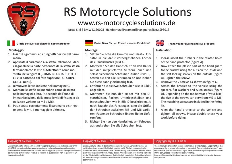
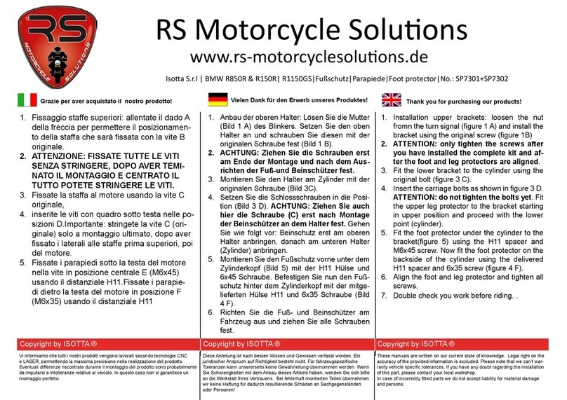
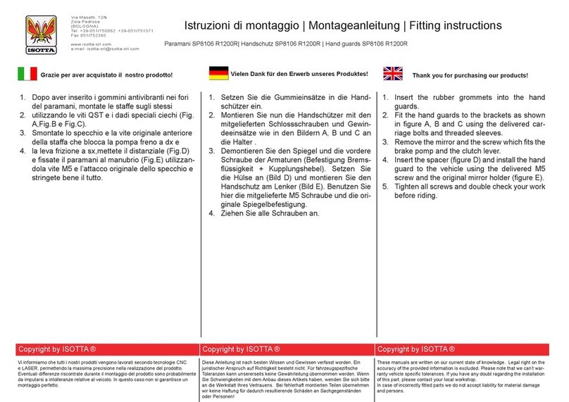
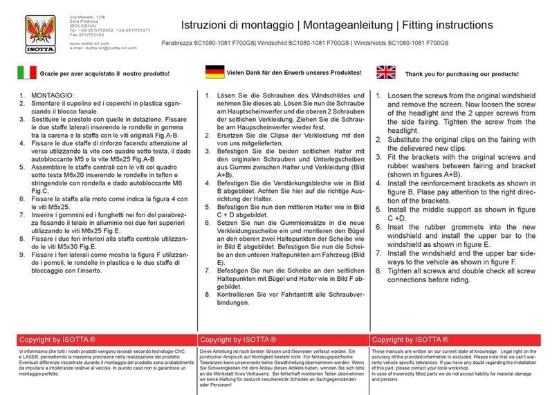
Isotta SC 1024 User manual

Rimuovete il coperchieo originale indicato nella gura A.Inserite
le clip leate (prestole) M5 e montate la staa come mostrato
nelle gure B + C. Sopra la staa meete la plasca copriforo e
fermate il tuo con le vi M5x20 + rondelle piane 5x15.
Svitate la vite originale e rimuovete le frecce scollegando-
le dal conneore(rimuovete il faro se necessario). Inserite il
cavo,dall’esterno verso l’interno,nel foro della staa e fermate la
frecce ulizzando la vite originale ed il dado autobloccante M6
come mostrato dalla gura D.
Rimuovete la vite originale indicata in gura E. La foto si riferisce
al mod.2006-2010, la vite del mod. 2011 si trova nella medesima
posizione.
Montate le stae portafreccia come mostrato dalla gura F. Fate
passare il cavo della freccia all’interno del foro presente nella
plasca originale; alloggiate il faro nella sua sede; inserite l’asola
in plasca originale all’interno del foro della staa e rimontate il
tuo ulizzando la vite originale; prima di stringere ricollegate i
conneori delle frecce.
Inserite il distanziale H9 al posto della vite originale precedente-
mente rimossa e montate la staa laterale come da gura G.
Montate le stae di ssaggio del cupolino come indicato dalla
gura H senza stringerle e facendo aenzione al verso.
Inserite i gommini nei fori del cupolino. Fissate il cupolino alle
stae mediante l’ulizzo delle vi QST M8 e le boccole leate
M8 come mostrato dalle gure I+J (non stringete le vi).
Regolate il cupolino nella posizione a voi ideale e stringete bene
tue le vi. Il montaggio è ulmato.
1.
2.
3.
4.
5.
6.
7.
8.
Enernen Sie den originalen Plaskdeckel wie im Bild A abge-
bildet. Setzen Sie die Clips mit M5 Gewinde ein und moneren
Sie den Halter (Bild B+C). Setzen Sie den Plaskhalter wieder
ein und moneren ihn mit den M5x20 Schrauben und achen
5x15 Unterlegscheiben an.
Enernen Sie beide Blinker. Drehen Sie hierfür die Befes-
gungsschrauben heraus. Trennen Sie die Blinker von der
Steckern (enernen Sie wenn nög auch den Scheinwerfer).
Führen Sie nun das Blinkerkabel wie in Bild D abgebildet von
Außen nach Innen durch den neuen Halter. Moneren Sie
den Blinker mit der originalen Schraube + selbstsichernde M6
Muer an den neuen Halter (Bild D).
Enernen Sie die in Bild E abgebildete Schraube.
Moneren Sie den Blinkerhalter wie in Bild F abgebildet. Füh-
ren Sie die Blinkerkabel durch die Bohrung der originalen Pla-
skverkleidung und verbinden Sie die Kabel wieder mit den
Steckern. Moneren Sie nun den Hauptscheinwerfer mit der
originalen Schraube (die originale Bananenscheibe wird an
dem neuen Halter eingesetzt).
Setzen Sie die H9 Hülse ansta der vorher enernten Origi-
nal Schraube ein und moneren Sie den seitlichen Halter (Bild
G.)
Moneren Sie nun die Befesgungshalter des Windschildes
wie in Bild H abgebildet. Achten Sie auch darauf, das die Halter
nicht vertauscht werden.
Setzen Sie die Gummitüllen in das Windschild und moneren
Sie die Scheibe mit den M8 Schlossschrauben + Spezialmut-
tern an das Fahrzeug (Bild I + J).
Stellen Sie das Windschild auf Ihre Bedürfnisse ein und ziehen
Sie alle Schrauben fest.
1.
2.
3.
4.
5.
6.
7.
8.
Remove the original plasc cover shown in gure A.
Install the clips with M5 thread and install the bracket
together with the plasc cover using M5x20 screws and
at 5x15 washers (gures B + C).
Loosen the screws from both indicators and remove
them. Disconnect the indicators from the connectors (if
necessary remove the headlight. Insert the indicator ca-
ble from the outside to the inside through the new bra-
cket (gure D). Install the indicators to the new bracket
using the original screw + self-locking nut (gure D).
Remove the bolt shown in gure E.
Install the indicator bracket to the vehicle (gure F).
Lead the indicator cables through the hole of the fairing
and re-connect them to the sockets. Install the head-
light with the original bolts. The banana shaped original
washer will be placed to the new bracket.
Insert the H9 spacer instead of the previous removed
original screw and install the lateral bracket (gure G).
Install the brackets of the windshield as shown in gure
H. Make sure that the brackets are not twisted.
Insert the rubber grommets to the windshield and in-
stall teh windshield using the M8 carriage screws + spe-
cial Allen nuts (gure I+J).
Adjust the windshield to your needs and ghten all
screws. Double check your work before riding.
1.
2.
3.
4.
5.
6.
7.
8.
Vi informiamo che tutti i nostri prodotti vengono lavorati secondo tecnologie CNC
e LASER, permettendo la massima precisione nella realizzazione del prodotto.
Eventuali differenze riscontrate durante il montaggio del prodotto sono probabilmente
da imputarsi a intolleranze relative al veicolo. In questo caso non si garantisce un
montaggio perfetto.
Diese Anleitung ist nach besten Wissen und Gewissen verfasst worden. Ein
juristischer Anspruch auf Richtigkeit besteht nicht. Für fahrzeugspezifische
Toleranzen kann unsererseits keine Gewährleitung übernommen werden. Wenn
Sie Schwierigkeiten mit dem Anbau dieses Artikels haben, wenden Sie sich bitte
an die Werkstatt Ihres Vertrauens. Bei fehlerhaft montierten Teilen übernehmen
wir keine Haftung für dadurch resultierende Schäden an Sachgegenständen
oder Personen!
These manuals are written on our current state of knowledge. Legal right on the
accuracy of the provided information is excluded. Please note that we can’t war-
ranty vehicle specific tolerances. If you have any doubt ragarding the installation
of this part, please contact your local workshop.
In case of incorrectly fitted parts we do not accept liability for material damage
and persons.
Copyright by RS Motorcycle Solutions ® Copyright by RS Motorcycle Solutions ® Copyright by RS Motorcycle Solutions ®
Grazie per aver acquistato il nostro prodotto! Vielen Dank für den Erwerb unseres Produktes! Thank you for purchasing our products!
Isoa S.r.l | BMW R1200R (-2010) |Windschild|Parabrezza|Windshield|No.: SC 1024
RS Motorcycle Soluons
www.rs-motorcyclesoluons.de

A B C
DEF
Vi informiamo che tutti i nostri prodotti vengono lavorati secondo tecnologie CNC
e LASER, permettendo la massima precisione nella realizzazione del prodotto.
Eventuali differenze riscontrate durante il montaggio del prodotto sono probabilmente
da imputarsi a intolleranze relative al veicolo. In questo caso non si garantisce un
montaggio perfetto.
Diese Anleitung ist nach besten Wissen und Gewissen verfasst worden. Ein
juristischer Anspruch auf Richtigkeit besteht nicht. Für fahrzeugspezifische
Toleranzen kann unsererseits keine Gewährleitung übernommen werden. Wenn
Sie Schwierigkeiten mit dem Anbau dieses Artikels haben, wenden Sie sich bitte
an die Werkstatt Ihres Vertrauens. Bei fehlerhaft montierten Teilen übernehmen
wir keine Haftung für dadurch resultierende Schäden an Sachgegenständen
oder Personen!
These manuals are written on our current state of knowledge. Legal right on the
accuracy of the provided information is excluded. Please note that we can’t war-
ranty vehicle specific tolerances. If you have any doubt ragarding the installation
of this part, please contact your local workshop.
In case of incorrectly fitted parts we do not accept liability for material damage
and persons.
Copyright by RS Motorcycle Solutions ® Copyright by RS Motorcycle Solutions ® Copyright by RS Motorcycle Solutions ®
G H I
J
Vite QST M6 (all‘interno rondella 6x18 +Dado autobl. M6)
Schlossschraube M6 (Innen U-Scheibe 6x18 + Selbstsichernde Mutter M6
M6 carriage bolt (6x18 washer and M6 self locking nut inside)
vite M6x18 + rondella 6x12
Schraube M6x18 + U-Scheibe 6x12
Screw M6x18 + washer 6x12
vite M8x35 + rondella ´8x16
Schraube M8x35 + U-Scheibe 8x16
Screw M6x35 + washer 8x16
Distanziale H9 all‘interno
H9 Hülse Innen
H9 spacer inside

Rimuovete il faro e il guscio coprifaro indicato in gura A.
Montate la staa centrale come mostrato dalle gure B + C soostan
(non stringete le vi,lasciatele lente in quanto dopo sarà impossibile inseri-
re nella propria sede il guscio coprifaro).
Svitate la vite originale e rimuovete le frecce scollegandole dal conneore
(se possibile, non tagliate le fascee in plasca che fermano i cavi alla
moto). Inserite il cavo,dall’esterno verso l’interno,nel foro della staa e
fermate la frecce ulizzando la vite originale ed il dado autobloccante M6
come mostrato dalla gura D.
Rimuovete la vite originale indicata in gura E.
Rimuovete il guscio in plasca; fate passare il cavo della freccia come mo-
strato nella gura G e ricollegate il conneore; rimontate il guscio facendo
aenzione che il cavo non rimanga schiacciato tra le par in plasca).
Montate la staa laterale come indicato nella gura H,facendo aenzione
al verso e senza stringere le vi (impuntatele soltanto); (tra la staa e la
boccola originale inserite una rondella 8x16).
Alloggiate il faro nella sua sede e montate la staa portafreccia come da
gura I. Inserite l’asola in plasca originale nel foro della staa e mediante
la vite originale ssate il tuo senza stringere. Tirate il cavo della freccia in
modo da lasciarne il meno possibile all’esterno.
Alloggiate nella propria sede il guscio coprifaro e stringete bene le vi che
fermano la staa centrale. Montate la staa inferiore cupolino (come da
gura J) senza stringere. Serrate bene le vi che fermano il fanale e le stae
laterali.
Montate le stae di ssaggio del cupolino come indicato dalla gura K
senza stringerle e facendo aenzione al verso.
Inserite i gommini nei fori del cupolino. Fissate il cupolino alle stae me-
diante l’ulizzo delle vi QST M8 e le boccole leate M8 come mostrato
dalle gure L (non stringete le vi).
Regolate il cupolino nella posizione a voi ideale e stringete bene tue le vi.
Il montaggio è ulmato.
1.
2.
3.
4.
5.
6.
7.
8.
9.
10.
11.
Enernen Sie die Abdeckung (Bild A) und den Hauptscheinwerfer.
Moneren Sie den Mileren Halter wie in den Bildern B + C abgebil-
det. Ziehen Sie die Schrauben nicht fest. Sonst wird es nicht möglich
sein, die Scheinwerferabdeckung später wieder zu moneren.
Enernen Sie beide Blinker. Drehen Sie hierfür die Befesgungs-
schrauben heraus. Trennen Sie die Blinker von der Steckern (wenn
möglich NICHT die Kabelbinder enernen). Führen Sie nun das Blin-
kerkabel wie in Bild D abgebildet von Außen nach Innen durch den
neuen Halter. Moneren Sie den Blinker mit der originalen Schraube
+ selbstsichernde M6 Muer an den neuen Halter (Bild D).
Enernen Sie die in Bild E abgebildete Schraube.
Enernen Sie die Plaskverkleidung. Verlegen Sie das Blinkerkabel
wie im Bild G abgebildet und verbinden Sie das Kabel wieder mit
dem Stecker. Moneren Sie die Verkleidung wieder ans Fahrzeug.
Achten Sie darauf, dass das Kabel nicht gequetscht wird.
Moneren Sie den seitlichen Halter wie im Bild H abgebildet. Ach-
ten Sie darauf dass die Halter nicht vertauscht werden. Setzen Sie
zwischen Halter und original Hülse die 8x16 Unterlegscheibe. Setzen
Sie die Schrauben nur an und ziehen Sie noch nicht fest.
Moneren Sie nun den Hauptscheinwerfer und den neuen Blinker-
halter (Bild I). Die originale Bananenscheibe wird an dem neuen
Halter eingesetzt. Verlegen Sie das Blinkerkabel, sodass dieses von
Außen nicht mehr sichtbar ist.
Moneren Sie nun die Scheinwerferabdeckung und ziehen Sie die
Schrauben des Halters fest (unter Abdeckung). Moneren Sie nun
den Windschild Halter (Bild J). Ziehen Sie alle Schrauben fest.
Moneren Sie nun die Befesgungshalter des Windschildes wie in
Bild K abgebildet. Achten Sie auch darauf, das die Halter nicht ver-
tauscht werden.
Setzen Sie die Gummitüllen in das Windschild und moneren Sie
die Scheibe mit den M8 Schlossschrauben + Spezialmuern an das
Fahrzeug (Bild L).
Stellen Sie das Windschild auf Ihre Bedürfnisse ein und ziehen Sie
alle Schrauben fest.
1.
2.
3.
4.
5.
6.
7.
8.
9.
10.
11.
Remove the headlight cover (gure A) and the headlight.
Install the central bracket as shown in the gures B+C. Do not
ghten the screws as it will be impossible to mount the head-
light cover later.
Remove both indicators screws and both indicators. Discon-
nect the indicator cables from the sockets (if possible, do not
remove the cable es). Lead the indicator cable from the out-
side to the inside through the new bracket (gure D) and in-
stall the indicator to the new bracket using the original screw
and the self-locking M6 nut gure D.)
Remove the screw as shown in gure E.
Remove the plasc cocer. Lead the cables as shown in gure
G and re-connect the indicator cable to the socket. Install the
plasc cover to the vehicle. Make sure that the cables will not
be pinched.
Instal the lateral brackets as shown in gure H. Make sure
that the brackets are placed in the right direcon. Place the
8x16 spacer between fairing and bracket. Do only ghten the
screws by a few turns.
Re-mount the headlight and the new indicator bracket (gure
I). The original banana shaped washer will be placed to the
new bracket. Pull the indicator cable unl it is no longer visible
from the outside.
Replace the headlight cover and ghten the bolts of the middle
bracket (gure J)..
Insert the rubber grommets to the windshield and install teh
windshield using the M8 carriage screws + special Allen nuts
(gure L).
Adjust the windshield to your needs and ghten all screws.
Double check your work before riding.
1.
2.
3.
4.
5.
6.
7.
8.
9.
10.
Grazie per aver acquistato il nostro prodotto! Vielen Dank für den Erwerb unseres Produktes! Thank you for purchasing our products!
Isoa S.r.l | BMW R1200R (2011-2014) |Windschild|Parabrezza|Windshield|No.: SC 1024
RS Motorcycle Soluons
www.rs-motorcyclesoluons.de
Vi informiamo che tutti i nostri prodotti vengono lavorati secondo tecnologie CNC
e LASER, permettendo la massima precisione nella realizzazione del prodotto.
Eventuali differenze riscontrate durante il montaggio del prodotto sono probabilmente
da imputarsi a intolleranze relative al veicolo. In questo caso non si garantisce un
montaggio perfetto.
Diese Anleitung ist nach besten Wissen und Gewissen verfasst worden. Ein
juristischer Anspruch auf Richtigkeit besteht nicht. Für fahrzeugspezifische
Toleranzen kann unsererseits keine Gewährleitung übernommen werden. Wenn
Sie Schwierigkeiten mit dem Anbau dieses Artikels haben, wenden Sie sich bitte
an die Werkstatt Ihres Vertrauens. Bei fehlerhaft montierten Teilen übernehmen
wir keine Haftung für dadurch resultierende Schäden an Sachgegenständen
oder Personen!
These manuals are written on our current state of knowledge. Legal right on the
accuracy of the provided information is excluded. Please note that we can’t war-
ranty vehicle specific tolerances. If you have any doubt ragarding the installation
of this part, please contact your local workshop.
In case of incorrectly fitted parts we do not accept liability for material damage
and persons.
Copyright by RS Motorcycle Solutions ® Copyright by RS Motorcycle Solutions ® Copyright by RS Motorcycle Solutions ®
DEF
A B C
Vite QST M5
M6 Schlossschraube
M6 Carriage bolt
Staffa di rinforzo
Verstärkungsblech
Reinforcement plate
Rondella 5x15 +Dado autobl. M5
Unterlegscheibe 5x15 + Selbstsichernde Mutter M5
5x15 washer and M5 self locking nut
Isoa S.r.l | BMW R1200R (2011-2014) |Windschild|Parabrezza|Windshield|No.: SC 1024
RS Motorcycle Soluons
www.rs-motorcyclesoluons.de
Vi informiamo che tutti i nostri prodotti vengono lavorati secondo tecnologie CNC
e LASER, permettendo la massima precisione nella realizzazione del prodotto.
Eventuali differenze riscontrate durante il montaggio del prodotto sono probabilmente
da imputarsi a intolleranze relative al veicolo. In questo caso non si garantisce un
montaggio perfetto.
Diese Anleitung ist nach besten Wissen und Gewissen verfasst worden. Ein
juristischer Anspruch auf Richtigkeit besteht nicht. Für fahrzeugspezifische
Toleranzen kann unsererseits keine Gewährleitung übernommen werden. Wenn
Sie Schwierigkeiten mit dem Anbau dieses Artikels haben, wenden Sie sich bitte
an die Werkstatt Ihres Vertrauens. Bei fehlerhaft montierten Teilen übernehmen
wir keine Haftung für dadurch resultierende Schäden an Sachgegenständen
oder Personen!
These manuals are written on our current state of knowledge. Legal right on the
accuracy of the provided information is excluded. Please note that we can’t war-
ranty vehicle specific tolerances. If you have any doubt ragarding the installation
of this part, please contact your local workshop.
In case of incorrectly fitted parts we do not accept liability for material damage
and persons.
Copyright by RS Motorcycle Solutions ® Copyright by RS Motorcycle Solutions ® Copyright by RS Motorcycle Solutions ®

GHI
J
Vite QST M6 (all‘interno rondella 6x18 +Dado autobl. M6)
Schlossschraube M6 (Innen U-Scheibe 6x18 + Selbstsichernde Mutter M6
M6 carriage bolt (6x18 washer and M6 self locking nut inside)
vite M6x18 + rondella 6x12
Schraube M6x18 + U-Scheibe 6x12
Screw M6x18 + washer 6x12
vite M8x35 + rondella ´8x16
Schraube M8x35 + U-Scheibe 8x16
Screw M6x35 + washer 8x16
Esterno Vite QST M6 - Interno rondella 6x18 +Dado autobl. M6)
Außen Schlossschraube M6- Innen U-Scheibe 6x18 + Selbstsichernde Mutter M6
Outside M6 carriage bolt - Inside 6x18 washer and M6 self locking nut
KL
Vi informiamo che tutti i nostri prodotti vengono lavorati secondo tecnologie CNC
e LASER, permettendo la massima precisione nella realizzazione del prodotto.
Eventuali differenze riscontrate durante il montaggio del prodotto sono probabilmente
da imputarsi a intolleranze relative al veicolo. In questo caso non si garantisce un
montaggio perfetto.
Diese Anleitung ist nach besten Wissen und Gewissen verfasst worden. Ein
juristischer Anspruch auf Richtigkeit besteht nicht. Für fahrzeugspezifische
Toleranzen kann unsererseits keine Gewährleitung übernommen werden. Wenn
Sie Schwierigkeiten mit dem Anbau dieses Artikels haben, wenden Sie sich bitte
an die Werkstatt Ihres Vertrauens. Bei fehlerhaft montierten Teilen übernehmen
wir keine Haftung für dadurch resultierende Schäden an Sachgegenständen
oder Personen!
These manuals are written on our current state of knowledge. Legal right on the
accuracy of the provided information is excluded. Please note that we can’t war-
ranty vehicle specific tolerances. If you have any doubt ragarding the installation
of this part, please contact your local workshop.
In case of incorrectly fitted parts we do not accept liability for material damage
and persons.
Copyright by RS Motorcycle Solutions ® Copyright by RS Motorcycle Solutions ® Copyright by RS Motorcycle Solutions ®
Other Isotta Motorcycle Accessories manuals

Isotta
Isotta SP7301 User manual

Isotta
Isotta SC1098 User manual

Isotta
Isotta SC916 User manual

Isotta
Isotta SP8106 R1200R User manual

Isotta
Isotta SP8012 User manual

Isotta
Isotta SC1086 User manual

Isotta
Isotta SP8150 User manual

Isotta
Isotta SC1080 User manual

Isotta
Isotta SP8106 User manual

Isotta
Isotta SP7847 User manual
Popular Motorcycle Accessories manuals by other brands

Low Range Off-Road
Low Range Off-Road SER-THC installation instructions

IBEX
IBEX 10006661 Mounting instruction

Dynojet
Dynojet POWER COMMANDER III installation instructions

kellermann
kellermann Micro 1000 PL installation manual

BMW Motorrad
BMW Motorrad LEGEND operating instructions

PUIG
PUIG 3173 Mounting instructions