Metel 200M-2.0.4.ECA User manual

www.metel.eu
Installation Manual
rev. 20110418
This document contains installation instructions for the switches of the following versions:
200M-2.0.4.ECA 2G-2.0.4.ECA
200M-2.0.4.ECB 2G-2.0.4.ECB
200M-2.0.4.H-ECA 2G-2.0.4.H-ECA
200M-2.0.4.H-ECB 2G-2.0.4.H-ECB
2G-2.0.4.S-ECA
2G-2.0.4.S-ECA
1 T e package contains
1.1 Switc
1.2 Power Supply Connector (modification BOX only)
1.3 DIN Rail-mountable kit (modification BOX only)
1.4 Mounting kit for a wall placement (modification BOX only)
1.5 Installation Manual
1.6 Product Datas eet
2 Software
The following freeware applications are available for download from www.metel.eu
Management software IMULand
oftware for R 485 communication over virtual COM ports VcomNet
U B drivers U B-driver
All applications are compatible with O Windows XP, Vista and Windows 7 (32, 64 bit).
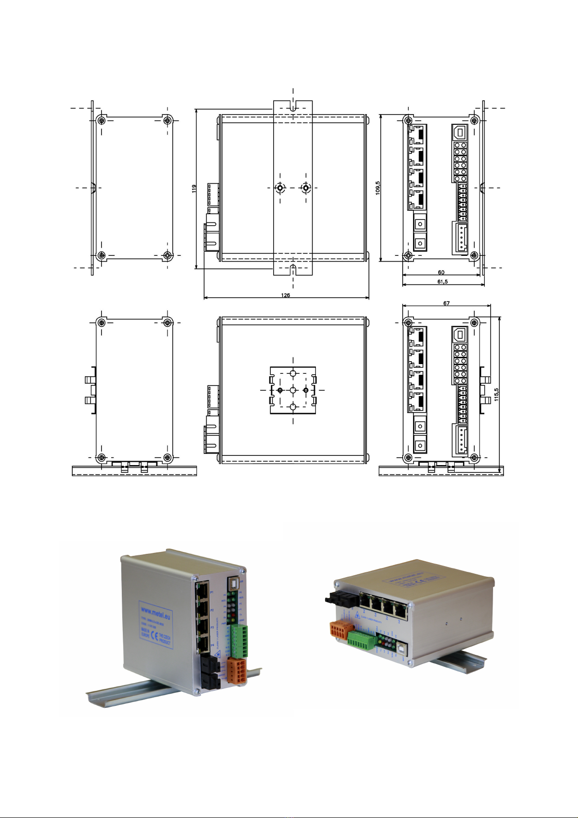
3 Mounting and Installation
3.1 BOX Modification
The package contains two screws M3x6 for flat surface placement
and DIN holder with bolts M3x6 for upright or parallel mounting to DIN35 rail.
1/11
www.metel.eu
2/11
www.metel.eu
4 Power Connection
4.1 BOX Modification
4.1.1 For non-PoE application it is recommended to use one of the the following
power supplies.
Supply Maximum
Power
Operational
Temperature
SU-230/4870H 70W -40°C...+50°C
SUP-48.120 120W -25°C...+70°C
TRF-2410T 10W -40°C...+50°C
TRF-2410T-IP55 10W -40°C...+50°C
TRF-2410T-IP55H 10W -40°C...+50°C
QS10.481 240W -25°C...+70°C
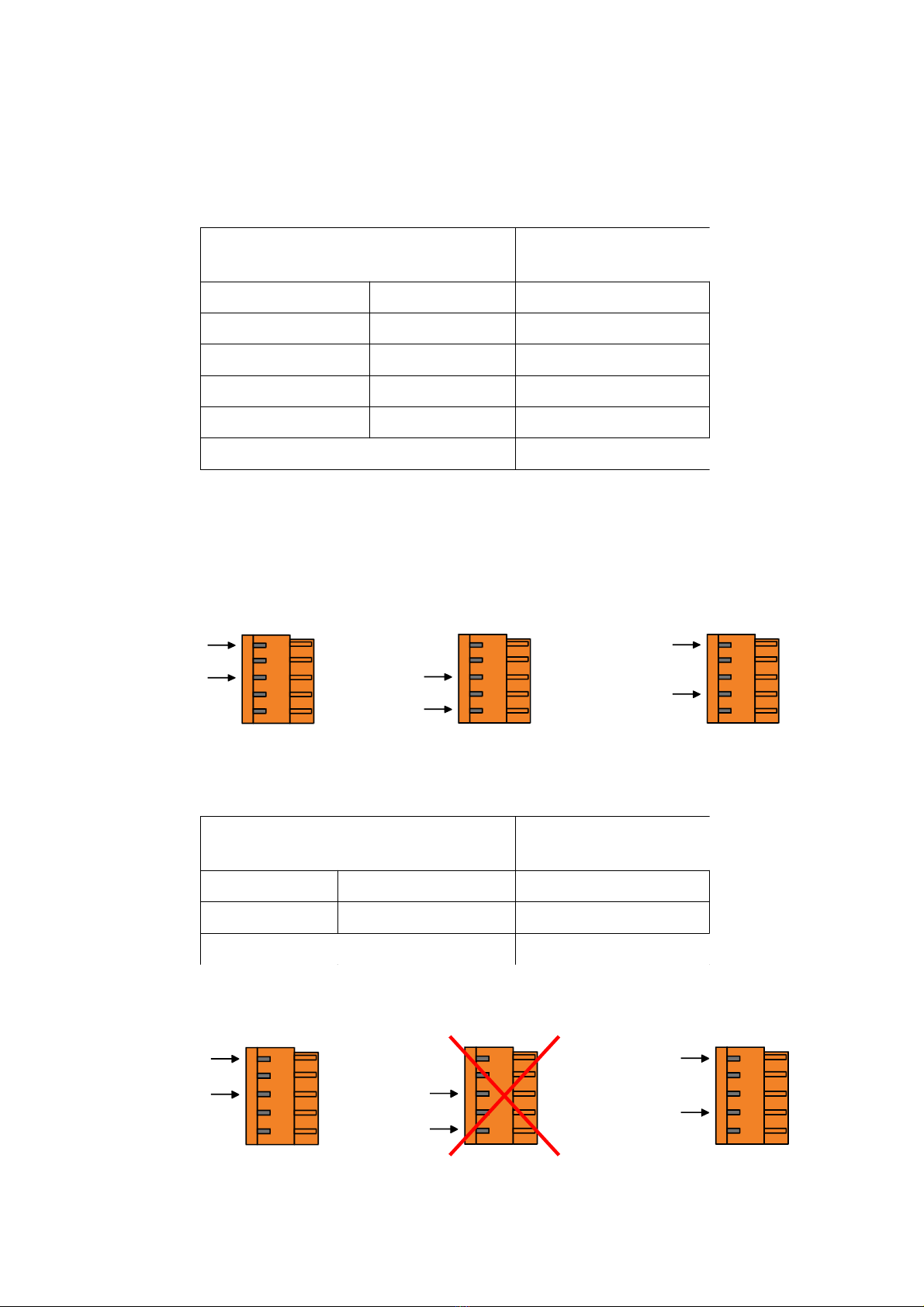
4.1.2 Power connection is described in the figures below.
4.1.3 Use two 1 - 1.5 mm² wires between the power supply and the switch. It is
recommended to tin the wires or to use a compression joint.
4.1.4 If redundant power is required use redundant power input (see the right figure).
VDC VAC REDUNDANT UPPLY
4.1.5 For PoE application it is recommended to use one of the the following power
supplies.
Supply Maximum
Power
Operational
Temperature
SU-230/4870H 70W -40°C...+50°C
SUP-48.120 120W -25°C...+70°C
QS10.481 240W -25°C...+70°C
4.1.6 Power connection is described in the figures below.
4.1.7 If redundant power is required use redundant power input (see the right figure).
VDC VAC REDUNDANT UPPLY
3/11
GND(PE)
10-60 VDC
GND(PE)
PoE
45-56 VDC
10-30 VAC
10-30 VAC
GND(PE)
PoE
45-56 VDC
GND(PE)
PoE
45-56 VDC
10-30 VAC
10-30 VAC

www.metel.eu
4.1.8 For use in alarm systems connect the switch to a supply complying with CSN
EN 50131-1 ed.2. Connect the supply according to the igure below.
5 Overvoltage Protection Grounding
5.1 BOX Modification
5.1.1 Ground the switch.
5.1.2 Ground resistance must not exceed 10 Ω.
5.1.3 Use min. 4mm
2
wire.
5.1.4 With higher ground resistance efficiency of overvoltage protections decreases.
5.1.5 Grounding cable length should be kept as short as possible.
5.2 Fast Et ernet Port Connection
5.2.1 Use RJ45 connector and cables UTP Cat5e.
5.2.2 UTP cable type must be selected based on the operational environment.
5.2.3 Ports can be used in outdoor environment without using any additional
overvoltage protection.
5.3 Gigabit Et ernet Port Connection
5.3.1 Use RJ45 connector and shielded cables FTP Cat6 or Cat6a.
5.3.2 FTP cable type must be selected based on the operational environment.
5.3.3 Ports can be used in outdoor environment without using any additional
overvoltage protection only for short distances up to 10m, e.g. within one pole. In
case of longer cable connection it is required to use additional overvoltage
protection.
4/11

www.metel.eu
6
Fiber Optic Port Connection
6.1 The switches are equipped with fiber ports with laser class 1 and wavelength 1310nm
and 1550nm. WARNING! Do not stare into the beam. Laser is invisible and is hazardous
to your eyes! We recommend using protection glasses with laser beam absorption.
6.2 When connecting optical ports apply “interconnection”, i.e. P7 of one switch to P6 of
the other switch and P6 of one switch to P7 of the other switch. ee the figure below.
6.3 Before the ring is closed one switch must be configured as MA TER to avoid loops in
network. ee par 8.
6.4 A properly connected port is indicated by GREEN LED switching on.
6.5 Data activity is indicated by blinking LED ACT.
6.6 Max. fiber length between ports is limited by the following table.
Fiber Power [dBm] Sensitivity [dBm] Distance [km]
200M MM (50-62.5/125μm) −10...0 −28 5
200M M (9/125 μm) −14...−8 −31 20
200M.
H
M (9/125 μm) -3...+2 -23 40
2G MM (50-62.5/125μm) −9...-3 −20 2
2G M (9/125 μm) −9...−3 −22 20
2G.H M (9/125 μm) -3...+2 -23 40
2G.S M (9/125 μm) 0...+5 -24 60
Parameter Value Unit Note
Waveleng t PORT 6: Tx 1310 / Rx 1550nm nm invisible radiation
PORT 7: Tx 1550 / Rx 1310nm nm invisible radiation
SAFETY
WARNING: converters contain laser sources CLASS 1 according to EN60825-1-1
7
Topology
7.1 Topology Point-to-Point and Bus
7.1.1 witches support connection both in topology point-to-point and optical bus.
The switches are already fully operational in default setting and priority LAVE.
7.2 Topology Optical Ring
7.2.1 witches support topology optical ring. Before the ring is closed it is necessary
to set Ring ID for all switches and one switch must be in MA TER mode.
In networks with multiple rings each ring must have a unique Ring ID. For detailed
settings see the following chapters or consult the Help for IMULand software.
5/11

www.metel.eu
7.3 Topology Optical Ring Complying with CSN EN 50131-1 ed.2.
De ault switch setting
200 and 2G-RS.E Other switches
Ring enabled Yes Yes
Ring ID 0 0
Relay Set to ring
interruption detection
(RING-OK)
RS485 port setting 9600kbps
8-N-1
9600kbps
8-N-1
Setting o Tx and Rx address
or port RS485
Rx: 239.192.168.1
Tx: 239.192.168.1
Rx: 239.192.168.1
Tx: -
When using the switches as transmission route in alarm systems it is necessary to:
7.3.1 Set one switch to MASTER mode
7.3.2 When using DOMINUS alarm systems set RS485 port to DOMINUS mode
(19.2kbps, 9-N-1 line reset support).
7.3.3 In case o interconnection o 2G and 200-RS.E switches with Ethernet switches
we recommend setting o packet iltering according to source MAC Addresses. The
iltering guarantees sa e separation rom the surrounding network.
6/11

www.metel.eu
8 Switc Configuration
8.1 IP Address, Mask and Gateway
8.1.1 Every switch has pre-set default configuration with mask 255.255.255.0 and
following IP addresses:
200M-R .E4 10.19.0.x 2G-R .E4 10.16.0.x
200M-R .E5 10.20.0.x 2G-R .E5 10.17.0.x
200M-R .E6 10.21.0.x 2G-R .E6 10.18.0.x
200M-2.0.1.E 10.22.0.x 2G-2.0.1.E 10.23.0.x
200M-2.1.4.E 10.9.0.x 2G-2.1.4.E 10.10.0.x
200M-2.0.4.ECA 10.24.0.x 2G-2.3.0.E 10.15.0.x
200M-2.0.4.ECB 10.25.0.x 2G-0.1.4.E 10.13.0.x
2G-0.1.8.E 10.14.0.x
x – corresponds to the last number of MAC address.
Please change the IP address if required. ee the figure below.
8.1.2 Run application IMULand (available on the website www.metel.eu )
8.1.3 elect menu „Project/Find devices“. Your computer must have a valid IP address
which is in the range used by the switches (default: 10.xxx.xxx.xxx and mask
255.255.255.0). Please check firewall settings if no device was found. A new rule
must be created for IMULand or Firewall must be turned off.
8.1.4 elect „Project/Find devices“ (Remote management)
7/11

www.metel.eu
8.1.5 Add the found devices to the workspace.
8.1.6 elect a device using the left mouse button and using the right mouse button
you can select „Configuration/Online configuration“.
8.1.7 Enter password. Default is “metel”.
8.1.8 In tab „IP“ insert required IP address, mask and gateway.
Confirm settings by pressing button „OK“ or „Apply“.
8/11
www.metel.eu
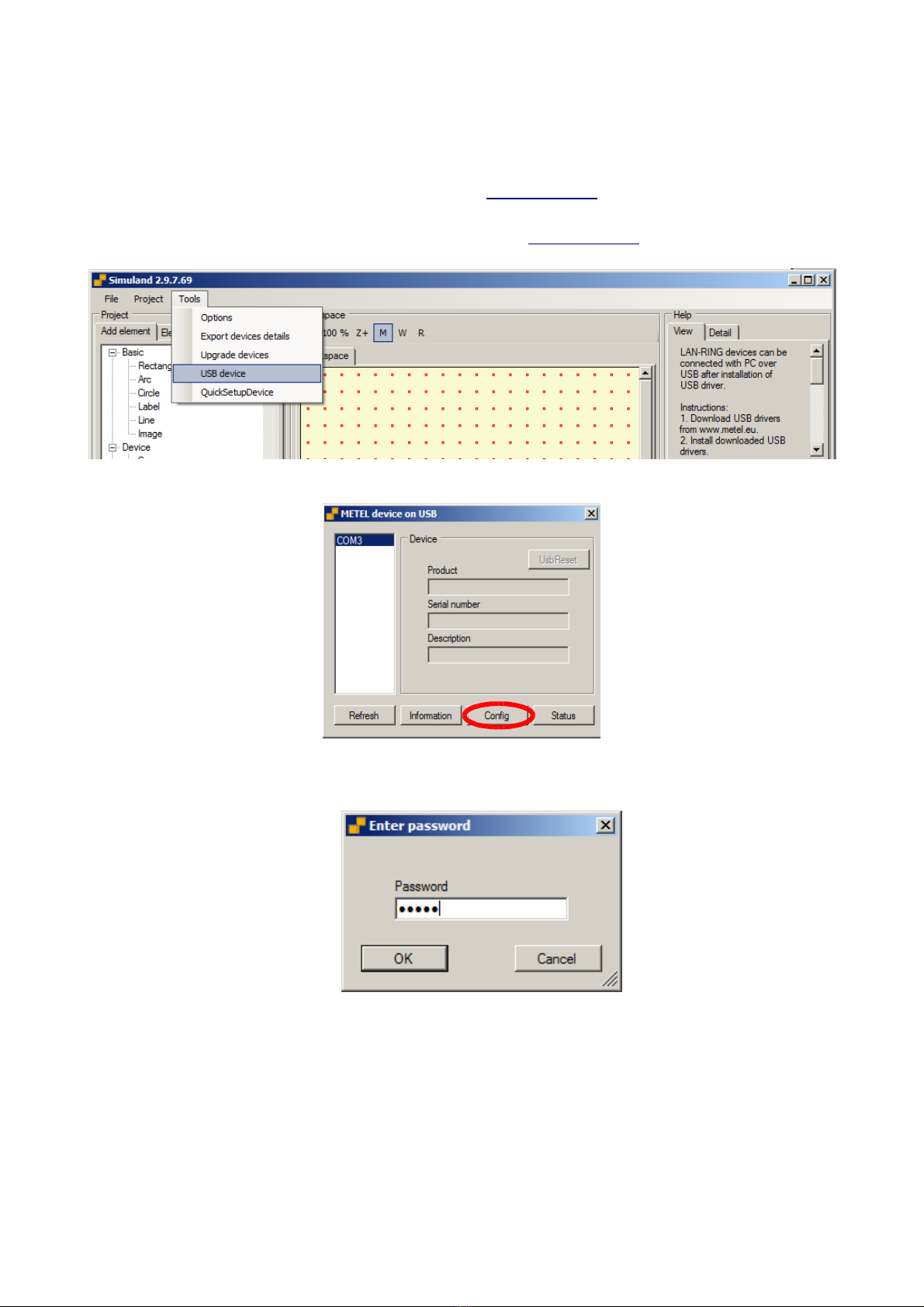
8.2 Local Management
8.2.1 Connect the device to a computer using U B-A-B cable (not included).
8.2.2 Install driver – for download from www.metel.eu (at32uc3xxx_cdc.inf)
8.2.3 Verify correct port assignment in Device manager.
8.2.4 Launch IMULand – for download from www.metel.eu
8.2.5 In menu select „Tools/U B Device“.
8.2.6 elect the port assigned by the system and press the „Configuration“ button.
8.2.7 Enter password. Default is “metel”.
8.2.8 Continue with steps defined in Remote management (8.1.8)
9/11

www.metel.eu
8.3 Configuration required for properly working ring - Before t e optical ring is closed!
8.3.1 For proper functioning of ring set in menu “Ring”
- it is required to have “Enabled” ring functionality on all switches on ring
- it is required to have one switch in “Master” mode
- all switches in the ring must have the same ring number “Ring ID”
8.3.2 In networks with multiple rings each ring (switches in one ring) must have a
unique number Ring ID (see menu Ring).
10/11
www.metel.eu
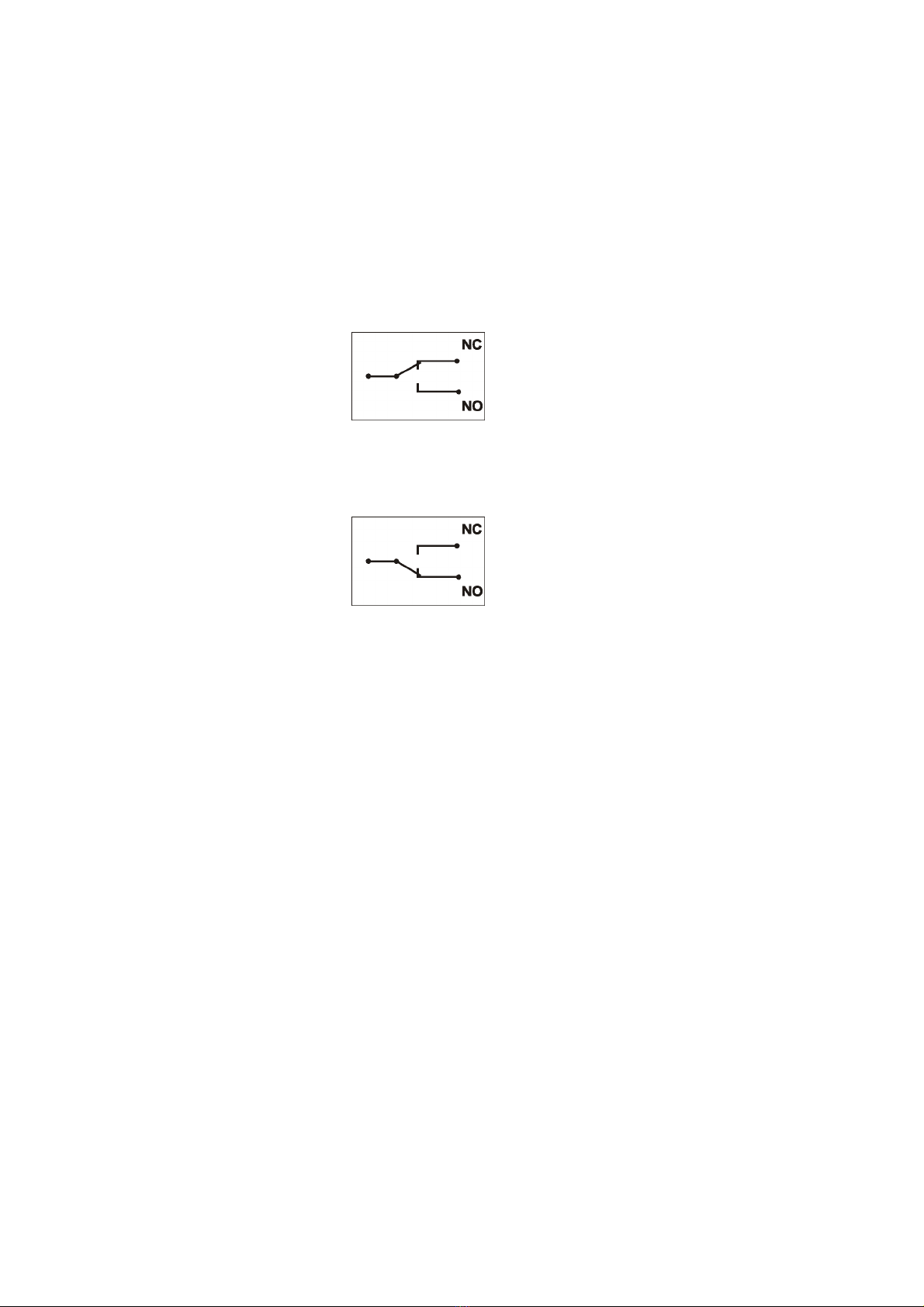
8.4 Indication of Optical Ring Failure or Sabotage
8.4.1 In case of ring interruption (failure or sabotage) the communication is
redirected in 30ms. The change of ring state (from 'loop' to 'backup') can be mapped
to a relay output on every switch.
8.4.2 Relay output state – depending on failure or sabotage:
Non-alarm state (under voltage and optical ring is closed)
Alarm state (optical ring open or supply failure)
For more information, see t e Help for SIMULand software.
11/11
This manual suits for next models
8
Table of contents
Other Metel Switch manuals


Popular Switch manuals by other brands


HP
HP StorageWorks 2/16 - SAN Switch Quick reference guide

Intellinet
Intellinet 560900 Quick install guide

LEGRAND
LEGRAND XMS-1208P Quick install guide

Panasonic
Panasonic CF-VEBU07W operating instructions

Moxa Technologies
Moxa Technologies EtherDevice EDS-G509-T Hardware installation guide

3Com
3Com 1000 user guide


